
Circuit Diagram
Index 1973
Drive White Light LED Circuit
Published:2011/4/26 Author:Joyce | Keyword: Drive, White Light, LED
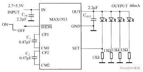
Input voltage of MAX1913 ranges from 2.7V to 5.3 V. it could provide stable output voltage or output current to drive the white light LED. As shown in the graph is a MAX1913 Drive White Light LED circuit . It needs only four small ceramic capacitors to fully compose DC/DC regulator without inductance. Its unique design of charge pump can decrease the input ripple and maintain a stable 750kHz switching frequency in a wide load range. MAX1913 also includes logic level turnoff and soft start function to decrease insurge current when activated.The main features are as follows.
(1) low input ripple, 750kHz working frequency.(2) current detection threshold of 200mV to reduce power consumption.(3) 60mA output current . 3% adjustable range of output compact.(4) 1μA shutoff current.(5) minute pin encapsulation . (View)
View full Circuit Diagram | Comments | Reading(771)
Light Control Switch Circuit Of Photodiode BPX63
Published:2011/5/1 22:44:00 Author:Christina | Keyword: Photodiode BPX63, Light Control Switch
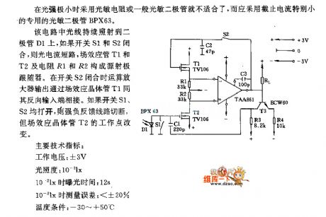
It is improper to use the photoresistor or general photodiode when the light intensity is minimum, and you should use the photodiode BPX63 which has very small cut-off current.
In this circuit, light continuously shine on the diode D1, if swich S1 and S2 close, the photocurrent will short circuit, FET T1,T2 and resistor R1,R2 constitute a source emitter follower. When the switch S2 closed, output power of op amp through the field-effect transistor T1 to connect the reverse input port. If swich S1,S2 open, the strong negative feedback circuit will be cut off, however, the work point of the field-effect transistor T2 will be change.
(View)
View full Circuit Diagram | Comments | Reading(1278)
Peak value hold circuit diagram composed of TP0032
Published:2011/5/2 7:18:00 Author:Nicole | Keyword: Peak value
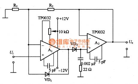
The figure of a peak value hold circuit composed of TP0032 is as shown. It is a high speed peak value hold circuit and isused to measure pulse. The biggest problem is the fidelity of narrow pulse. Although operational amplifier is very narrow, it also needs charging time when the diode charges to capacitance, so the width of measured pulse should not be too narrow.
(View)
View full Circuit Diagram | Comments | Reading(802)
Peak value hold circuit diagram composed of CA3130
Published:2011/5/2 7:08:00 Author:Nicole | Keyword: Peak value
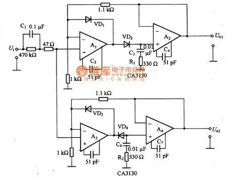
As shown in the figure, it is a peak value hold circuit which is composed of CA3130. This is a positive input, positive output and negative input, negative output circuit. If the output of negative peak value hold circuit is reversed by operational amplifier, then it will be the positive output circuit, do the same treatment to positive peak value. To change C3、R1 and C6、R2, it can make the output characteristic of pulse widths in frequency band flat. When A1 input is negative singal, VD1 turns on, it can prevent A1 ring working. As the same, VD3 is used to avoid A3 ring work. To add multiple negative feedback, it can reduce the nonlinear influence of VD2 and VD4.
(View)
View full Circuit Diagram | Comments | Reading(2363)
Car audio btl amplifier IC figure
Published:2011/5/1 22:44:00 Author:Christina | Keyword: Car audio, btl amplifier IC
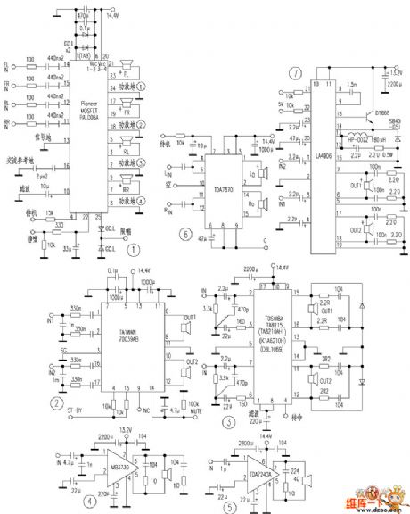
This article introduces the amplifier section of the car's sound system by my measurement and information collection.
1.brand device's specific IC
Figure 1 is the pal006a which is produced by the Pioneer company (Measurement model deh-p3300), this ic uses the mosfet output class and is in the 25-pin unilateral double-row zigzag package, it has 4 btl amplifiers with the maximum power of 50Wx4. Figure 2 is the Ford xllf-18c870-ed's amplifier class which is produced by the Alpine company. This ic is the philips 70039ab model, and is 17-pin unilateral dual in-line package, it has two groups of btl circuit. This ic is also used in Clarion Corporation's radio.
2.ta8210ah ~ ta8215l series of btl stereo ic that can be used in wide range of applications
Figure 3. The ta8210ah is in 17-pin unilateral dual in-line package, ta82l5l is in 17-pin single in-line package.
3.Mono btl specific ic
4.Other btl specific ic
(View)
View full Circuit Diagram | Comments | Reading(7491)
Simple pressure sensor amplification circuit diagram
Published:2011/5/2 7:06:00 Author:Nicole | Keyword: pressure sensor, amplifition
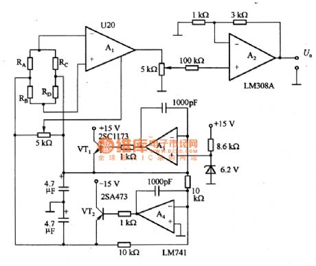
The figure 1 is a simple pressure sensor amplification circuit. Preamplifier A1 adopts 200 times fixed gain pressure sensor special preamplifier U2O. When it is standard load, you can use four and a half digital voltmeter to ontain data, the sensitivity is 2mV/V.
(View)
View full Circuit Diagram | Comments | Reading(3518)
Ultrashort wave antenna amplifier circuit
Published:2011/5/2 9:06:00 Author:Christina | Keyword: Ultrashort wave, antenna, amplifier

The Ultrashort wave antenna amplifier circuit is as shown:
(View)
View full Circuit Diagram | Comments | Reading(685)
Independent charger composed of LP3945
Published:2011/4/29 5:09:00 Author:Nicole | Keyword: charger
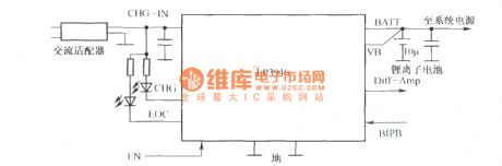
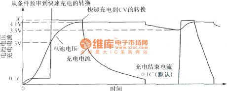
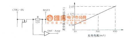
LP3945 is an independent single lithium ion battery charger, it consists of a integrated pass transistor and current detection resistor. Besides charging function, it is also used for low pressure drop pattern. This function is especially useful during the manufacture, bacause it is not needed to connect lithium ion battery when there is product testing and performance verification. The independent charger circuit composed of LP3945 is as below:
The charging period of LP3946 is shown as below:
The charging current induction circuit is shown as below:
(View)
View full Circuit Diagram | Comments | Reading(641)
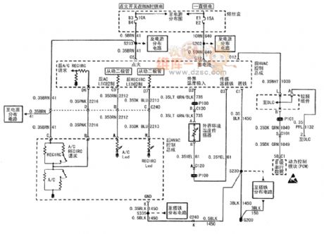
TOYOTA COASTER only warm wind control air conditioner circuit diagram
Published:2011/5/2 7:01:00 Author:Nicole | Keyword: TOYOTA COASTER, warm wind control, air conditioner
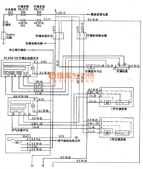
The other air conditioner control circuit diagram is shown in the figure 17, there is no refrigerant air conditioner amplifier, compressor and condenser fan.
(View)
View full Circuit Diagram | Comments | Reading(957)
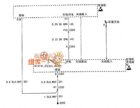
Shanghai GM BUICK commercial vehicle(GL8) audio system circuit diagram
Published:2011/4/29 5:06:00 Author:Nicole | Keyword: Shanghai GM BUICK, commercial vehicle, audio system
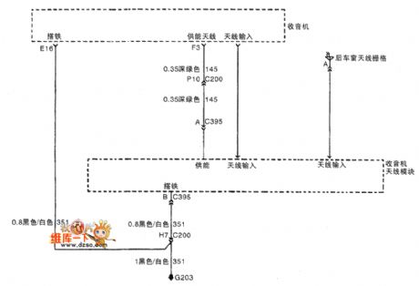
Shanghai GM BUICK commercial vehicle(GL8) audio system rear window antenna and radio antenna module circuit diagram.
(View)
View full Circuit Diagram | Comments | Reading(871)
Buick Century car HVAO system circuit diagram(2)
Published:2011/5/2 7:01:00 Author:Nicole | Keyword: Buick Century, car, HVAO system
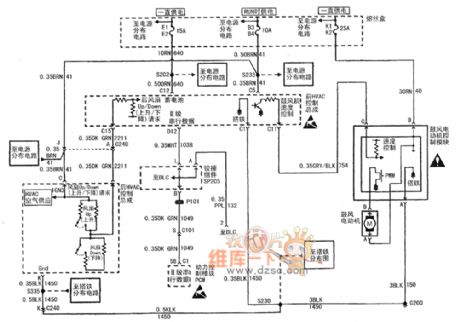
Shanghai GM Buick Century car HVAO system circuit(2)Former and rear HVAO control assembly, PCM, blast motor control module and blast motor(OJ4) (View)
View full Circuit Diagram | Comments | Reading(820)
RF2320 linear general amplifier pin circuit
Published:2011/5/2 2:25:00 Author:Christina | Keyword: linear, general amplifier, pin circuit
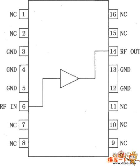
The RF2320 is one kind of general-purpose, low-cost, high-efficiency linear RF amplifier IC, this device has the GaAs heterojunction bipolar transistor (HBT) treatment, and it is designed for the cascade 75Ω gain circuit (Value of noise is less than 2dB), in the range of 5~1000 MHz, the gain flatness is better than 0.5dB, high linearity makes this device can be used in the cable and TV applications. Also the RF2320 can be used in wireless voice and data communications products' IF and RF amplification, the band up to 2500MHz, the device itself contains the 75Ω, the input impedance and output impedance and it supplies the 2:1 VSWR (Voltage Standing Wave Ratio). The RF2320 CATV can be used in distribution amplifier, cable modem, broadband gain blocks, laser diode driver, reciprocating-channel amplifier, base station applications. And the RF2320 is in the square bat-winged SOP-16 package, the pin out is as shown in figure.
(View)
View full Circuit Diagram | Comments | Reading(748)
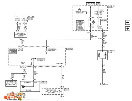
Buick Century car HVAO system circuit(4)
Published:2011/5/2 6:58:00 Author:Nicole | Keyword: Buick Century, car, HVAO system
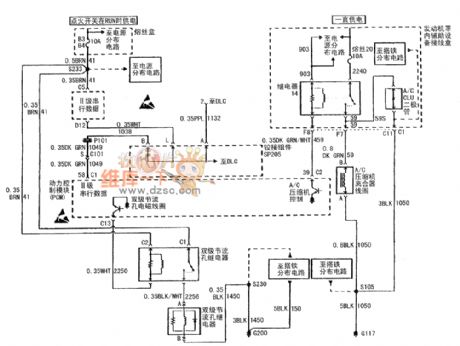
Shanghai GM Buick Century car HVAO system circuit(4)Former HVAO control assembly, PCM, A/C compressor clutch coil, A/C CLU relay and A/C CLU diode(OJ4) (View)
View full Circuit Diagram | Comments | Reading(1002)
Buick Century car HVAO system circuit(5)
Published:2011/5/2 6:55:00 Author:Nicole | Keyword: Buick Century, car, HVAO system
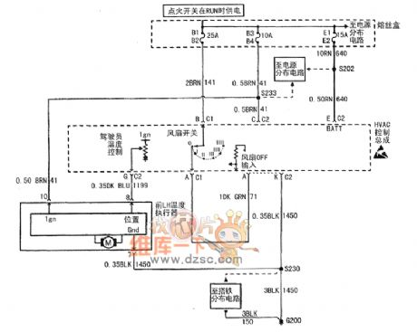
Shanghai GM Buick Century car HVAO system circuit(5)HVAO control assembly and LH temperature actuator(O60) (View)
View full Circuit Diagram | Comments | Reading(485)
Buick Century car HVAO system circuit(6)
Published:2011/5/2 6:53:00 Author:Nicole | Keyword: Buick Century, car, HVAO system
Shanghai GM Buick Century car HVAO system circuit(6)Former and rear HVAO control assembly, PCM and external environment temperature sensor(OJ4) (View)
View full Circuit Diagram | Comments | Reading(546)
Buick Century car audio system circuit diagram(3)
Published:2011/5/2 6:50:00 Author:Nicole | Keyword: Buick Century, car, instrument board
View full Circuit Diagram | Comments | Reading(507)
thermometer radiation circuit
Published:2011/5/1 23:39:00 Author:Christina | Keyword: thermometer, radiation
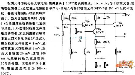
Detection device is the PbS photoresistor, it can detects the surface temperature higher than 100 ℃. TR1 ~ TR9 are the three-step amplifier that is installed on the detector. The bootstrap effect of the off-bias circuit makes the input voltage match with the radiation monitor device (61SV)'s 300kΩ impedance. Levels were added the bias to minimize the noise. When the ambient temperature rises, thermistor with the 2kΩ negative temperature coefficient adjusts the gain, to compensate the lower of the radiation detect device's sensitivity. The last stage of follower drives the main amplifier and instruction meter. Radiation detect device outputs 0.3mV, and this voltage gets through the pre-amplifier then becomes 1mV, the main amplifier outputs 20mV, it is in the range of 200uA ammeter's most sensitive range (deviation in 10%). This circuit has five ranges, the temperature range is 100 ~ 500 ℃.
(View)
View full Circuit Diagram | Comments | Reading(782)
Buick Century car HVAO system circuit(7)
Published:2011/4/29 5:00:00 Author:Nicole | Keyword: Buick Century, car, HVAO system
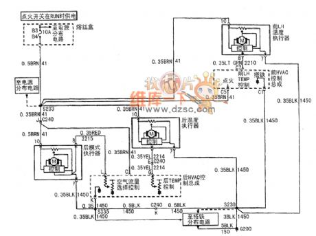
Former and later HVAO control assembly, later mode actuator, former LH temperature actuator, twin-stage orifice relay and electromagnetic coil. (View)
View full Circuit Diagram | Comments | Reading(543)
Shanghai GM Cadillac CTS car air condition system circuit diagram(4)
Published:2011/4/29 5:05:00 Author:Nicole | Keyword: Shanghai GM, Cadillac, CTS car, air condition system
View full Circuit Diagram | Comments | Reading(563)
Infrared Control Electronic Ceremonial Speech Device Circuit Using TX05D
Published:2011/5/2 4:14:00 Author:Robert | Keyword: Infrared Control, Electronic Ceremonial Speech Device
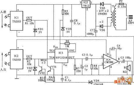
Infrared Control Electronic Ceremonial Speech Device Circuit Using TX05D is shown below:
(View)
View full Circuit Diagram | Comments | Reading(548)
| Pages:1973/2234 At 2019611962196319641965196619671968196919701971197219731974197519761977197819791980Under 20 |
Circuit Categories
power supply circuit
Amplifier Circuit
Basic Circuit
LED and Light Circuit
Sensor Circuit
Signal Processing
Electrical Equipment Circuit
Control Circuit
Remote Control Circuit
A/D-D/A Converter Circuit
Audio Circuit
Measuring and Test Circuit
Communication Circuit
Computer-Related Circuit
555 Circuit
Automotive Circuit
Repairing Circuit