
Circuit Diagram
Index 1971
Differential Amplifier Circuit
Published:2011/5/3 1:57:00 Author:Felicity | Keyword: Differential Amplifier Circuit,
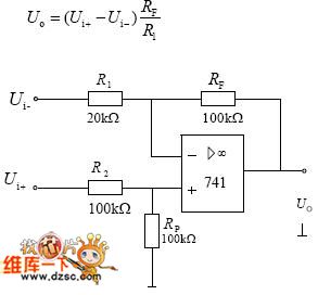
The way of differential connection: the input signal of differential amplifier circuit is inputed from integrated operational amplifier's phase and RP. If the feedback resistanceRF equals to the input resistance, in-phase input voltage minus phase input voltage is the the output voltage. This circuit is also called subtraction circuit. (View)
View full Circuit Diagram | Comments | Reading(589)
SCM buzzer relay circuit
Published:2011/5/3 1:41:00 Author:TaoXi | Keyword: SCM, buzzer relay
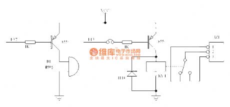
The SCM buzzer relay circuit is as shown:
(View)
View full Circuit Diagram | Comments | Reading(645)
DC-AC thin power meter appearance circuit diagram
Published:2011/5/3 1:45:00 Author:Ecco | Keyword: DC, AC , thin, power meter , appearance
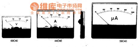
DC-AC thin power meter is a new electric meter, which uses an ideal supporting structure of silk sheets, with good resistance to vibration and impact capacity. Thickness is below I5mm, and it is suitable for miniaturization and integration of electronic equipment, instruments, communications equipment and radio equipment, it is is the replacements of mounted meter.
(View)
View full Circuit Diagram | Comments | Reading(514)
The protection circuit diagram composed of negative resistance leds
Published:2011/5/3 1:33:00 Author:Ecco | Keyword: protection circuit , negative resistance , led
View full Circuit Diagram | Comments | Reading(584)
DC-AC installed power meter appearance circuit diagram
Published:2011/5/3 1:38:00 Author:Ecco | Keyword: DC, AC , installed power meter, appearance
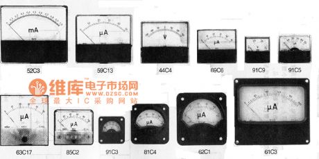
DC-AC installed power meter appearance is shown as the chart.
(View)
View full Circuit Diagram | Comments | Reading(496)
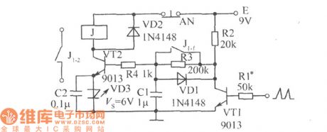
Hypoxia monitoring circuit diagram
Published:2011/5/3 1:24:00 Author:Nicole | Keyword: hypoxia, monitoring
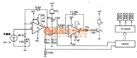
The figure 1 is a hypoxia monitoring circuit. Its sensor adopts battery oxygen sensor OS-12. In the oxygen concentration range of 0%~100%, OS-12 has characteristic of linear output, if the sensor output is connected to A/D converter, then it can accurately display the monitored oxygen concentration as digital form. Hypoxia monitoring circuit uses 3 LED nixietubes to display the monitored oxygen concentration, when the oxygen concentration is less than 18%, buzzer B will send out hypoxia warning singal.
A1 is DC amplifier, it can amplify the sensor output about 20 times, the amplified singal is added to LD130, 3 LED nixietubes are drived by decoding driver TC5002P, the oxygen concentration will be dispalyed as digital form. VD1 is constant current diode, it provides LDl30 with 2V voltage reference. It also provides A2 comparator circuit in-phase input terminal with voltage reference. To adjust RP4 to make the oxygen concentration is less than 18%, then A2 outputs high level, VT1 turns on, B sends out alarm.
(View)
View full Circuit Diagram | Comments | Reading(2527)
AC power supply working status indication circuit
Published:2011/5/3 1:19:00 Author:Ecco | Keyword: AC power supply , working status , indication circuit
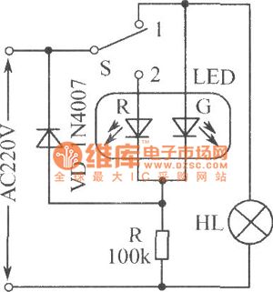
AC power working condition indicating circuit is shown as the chart, S is the 2 S 1 switch, when S is set to 1 position, the bulb HL gets power and emits light, while LED-G emits green light and it is used as the load working instructions; when the S sets 2 bit, HL is off, LED-G is extinguished, only the LED-R emits red light, which is used as indicating mains supply.
(View)
View full Circuit Diagram | Comments | Reading(569)
Dual LED alternate flasher circuit diagram
Published:2011/5/3 1:13:00 Author:Ecco | Keyword: Dual, LED, alternate , flasher
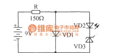
The chart shows the dual LED alternate flasher circuit diagram. It is an interesting two alternately flashing circuit only composed of four elements. VD1 is a flashing light-emitting diode, VD2 is the ordinary light emitting diode. The working course is as follow: VD1 needs 5V, 30mA. When it gets power, VD1 light turns on when there is about 5V voltage being applied to the VD2 and VD3 in series, VD3 is 6.2V regulator diode, so VD3 does not work, then only the VD1 stops, the supply voltage is added to the VD2, VD3 by being limited by R, and then VD3 regulator works, the current flowing through the VD2 and it emits light, VD1 flashing, VD1, VD2 shine alternately.
(View)
View full Circuit Diagram | Comments | Reading(1094)
5V/10A 20kHz blocking ammeter transformator using SIPMOS transistor
Published:2011/4/19 21:48:00 Author:May | Keyword: 5V/10A 20kHz, blocking ammeter transformator, SIPMOS transistor
This circuit is convertor which can change input DC voltage (+20~+30V) to lower DC output voltage (+5V). Integrated circuit TDB0555B is time base circuit which can generate 20kHz square wave. The timing time of output (pin 3) is between 10~40μs. Fixed bias can make T1 to break over. Square wave voltage outputted by TDB0555B is differential to triangle wave voltage by R4, C5 and R6+R7. It also can make T1 to cut off. So T1's output is square wave. Then the transformer can output AC and DC voltage after rectifying and filtering before passing opposite phase grade, drive grade and power amplifier grade.Main technical data: input voltage: +20~30V (rated value is 24V);output voltage: +5V;output current: 10A;network voltage adjustment rate: ±0.5%;load voltage adjustment rate: ±2%;efficiency: 78% (when the input voltage is 24V) (View)
View full Circuit Diagram | Comments | Reading(612)
Bridge type voltage regulator circuit using voltage regulator tube
Published:2011/4/19 22:17:00 Author:May | Keyword: Bridge type, voltage regulator, voltage regulator tube
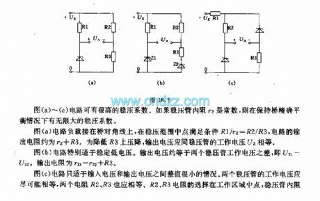
The circuits in diagram (a)~(c) can have very high voltage-regulation coefficient. If voltage regulator tube's internal resistance rz is constant, it has infinity voltage-regulation coefficient when the bridge is keeping precise balance.
The circuit load in diagram (a) is connecting on the bridge diagonal line. When the middle point on the voltage regulation range is satisfying the condition of R1/rz=R2/R3, the resistance of this circuit is about rz+R3. In order to drop down the voltage loss of R3, output voltage must be equal to voltage regulator tube's working voltage.
The circuit in diagram (b) is particularly suitable for stable low voltage. Output voltage is approximately equal to the difference of two voltage regulator tube's working voltage, Uz1-Uz2. Output resistor is rz1-rz2+R3.
The circuit in diagram (c) is only suitable for the situation when the difference value between input voltage and output voltage is very small. The working voltage of two voltage regulators tube is better to be equal. Two resistors R2 and R3 should be the same too. Selection of R2, R3 is middle of working area. (View)
View full Circuit Diagram | Comments | Reading(877)
Single flashing light-emitting diode application circuit
Published:2011/5/3 1:04:00 Author:Ecco | Keyword: Single, flashing , light-emitting diode , application circuit
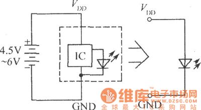
The chart shows the single flashing LED application circuit. The working frequency of blinking light-emitting diodes is only a few hertz, it is easy to arouse people's attention, it can be widely used in all kinds of alarm circuits, such as temperature, liquid level, the more limited voltage alarm circuit.
(View)
View full Circuit Diagram | Comments | Reading(853)
Fuse fusing indicator circuit diagram
Published:2011/5/3 0:56:00 Author:Ecco | Keyword: Fuse fusing indicator
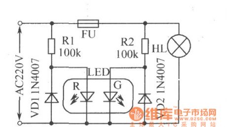
The chart shows the fuse fusing indicator circuit diagram. LED-R is used for the AC power indicator, LED-G is a fuse FU status indicator. When FU is normal, the two LEDs are lit and emit orange light; when FU blows, LED-G is off, only the LED-R emits red light. Limiting resistor R10, R2 can be replaced by the 220nF/450V capacitor, VD1, VD2 can be saved.
(View)
View full Circuit Diagram | Comments | Reading(1170)
Logic level test circuit diagram
Published:2011/5/3 0:49:00 Author:Ecco | Keyword: logic level, test
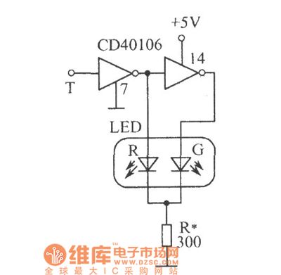
Logic level test circuit is shown as the chart. CD40106 is six inverter with a Schmitt trigger, T is the probe, when the T contacting point is 0 , after driven by inverting, LED-R emits red light, LED-G is off; when the detection point is 1 , LED-R reverse bias is off, but after being twice reversed, LED-G emits green light; when the T detects CP pulse, the two tube is lit alternately. As the clock pulse frequency is higher, while it is higher than 24Hz, the two tubes seem like being lit simultaneously because of the visual pictures effect of eyes, rather than flash alternately, the light is orange.
(View)
View full Circuit Diagram | Comments | Reading(1097)
TOYOTA COASTER coach wiring harness connector(engine block, instrument cluster) circuit wiring circuit diagram
Published:2011/5/3 0:42:00 Author:Nicole | Keyword: TOYOTA COASTER, coach, wiring harness, connector, engine block, instrument cluster
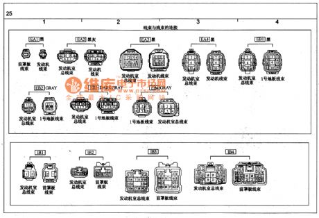
View full Circuit Diagram | Comments | Reading(1515)
Regulated votlage micro-switching power supply (3W-10W circuit diagram)
Published:2011/4/22 6:46:00 Author:May | Keyword: Regulated votlage, micro-switching power supply, 3W-10W
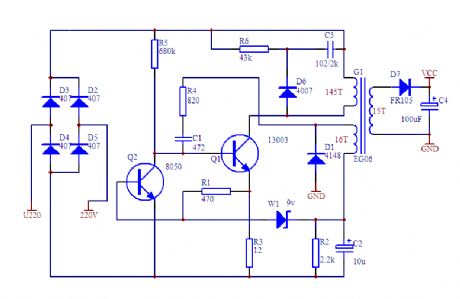
View full Circuit Diagram | Comments | Reading(6681)
Open circuit, short circuit anti-theft alarm circuit diagram
Published:2011/5/2 22:55:00 Author:Ecco | Keyword: Open circuit, short circuit , anti-theft , alarm circuit
AC driving light-emitting diodes can make higher output optical power, the driving circuit form is shown as the chart. The two LEDs are connected reversely in parallel, so that the positive and negative half-cycle of power have a light-emitting diode to display. (View)
View full Circuit Diagram | Comments | Reading(1151)
TOYOTA COASTER coach wiring harness connector(instrument cluster) circuit wiring circuit diagram
Published:2011/5/2 23:01:00 Author:Nicole | Keyword: TOYOTA COASTER, coach, connector, instrument cluster, wiring harness
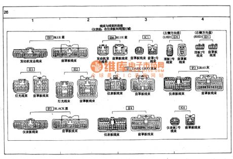
View full Circuit Diagram | Comments | Reading(4502)
Inverter drive signal generator circuit diagram
Published:2011/5/2 22:48:00 Author:Ecco | Keyword: Inverter , drive s, ignal generator
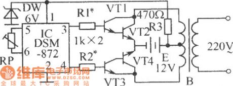
In the circuit shown as the chart, V1 ~ V4 are two composite switch amplifier tubes, of which V2 and V4 can be made by a few high-power tubes in parallel according to the power requirements of the inverter. B is the step-up transformer. Adjusting the resistance of RP could make the pin 3,4 IC output high and low frequency with 50Hz alternately. When the pin 3 outputs high level, VT1, VT2 are in saturation, VT3, VT4 end, when the pin 4 outputs high level, VT3, VT4 are in saturation, VT1, VT2 are closed. So the transformer generates electricity in two windings of the primary coil, the secondary coil can sense 220V, 50Hz square-wave voltage. (View)
View full Circuit Diagram | Comments | Reading(948)
High input impedance broadband amplifier circuit diagram composed of field effect pair transistor
Published:2011/5/2 22:46:00 Author:Nicole | Keyword: impedance, broadband, amplifier, field effect, pair transistor
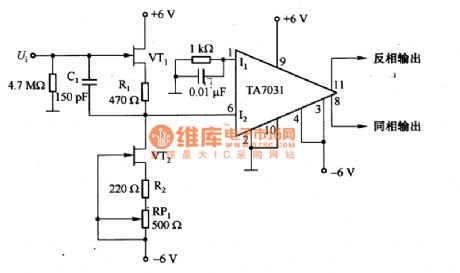
The figure 1 is as shown, it is a high input impedance broadband amplifier which is composed of field effect pair transistor. In the circuit, field effect pair transistor VT1 is connected to VT2, VT2 is as constant current source, UGS's drift of VT1 is decided by R1, then the input is equal to output voltage, the single terminal output is added to the differential amplifier TA7031. Compared this circuit's frequency characteristic to TA7031's frequency characteristic, it is dropped less than 1dB nearby lOMHz, the maximum output voltage is 3V. C1 is feedforward compensation capacitance.
(View)
View full Circuit Diagram | Comments | Reading(730)
Using ER1211 ASIC as automatic exposure control circuit diagram
Published:2011/5/2 20:53:00 Author:Rebekka | Keyword: ASIC, automatic exposure control
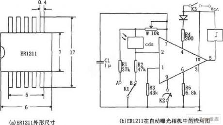
The figure shows the diagram of using ER1211 ASIC as automatic exposure control circuit. ER1211 is the automatic exposure control ASIC in the automatic camera. The pin arrangement is shown in Figure (a), ① is the supply voltage monitoring, ② is the illumination monitoring, ③ is grounding, ④ is illumination warning output, ⑤ is relay drive output, ⑥ is exposure time delay device, ⑦ is exposure delay input, ⑧Automatic focus control, ⑨ is exposure control, ⑩ is power Vcc. When the shutter button is in the mode of half-pressed K2. If illumination environment light is lower than limit (V2 ≤ V6-0.2V), ④ pin outputs low level, low-light warning light LED light. Linkage with the flash K-selector switch is opened at the receiving position A, the corresponding C1 pass W, R1 to discharge, the exposure time (discharge time) is fixed, even if the flash automatic metering circuit does not work.
(View)
View full Circuit Diagram | Comments | Reading(825)
| Pages:1971/2234 At 2019611962196319641965196619671968196919701971197219731974197519761977197819791980Under 20 |
Circuit Categories
power supply circuit
Amplifier Circuit
Basic Circuit
LED and Light Circuit
Sensor Circuit
Signal Processing
Electrical Equipment Circuit
Control Circuit
Remote Control Circuit
A/D-D/A Converter Circuit
Audio Circuit
Measuring and Test Circuit
Communication Circuit
Computer-Related Circuit
555 Circuit
Automotive Circuit
Repairing Circuit