
Circuit Diagram
Index 1975
The California SR-190 cool refrigerator circuit
Published:2011/5/2 5:05:00 Author:Christina | Keyword: California, cool refrigerator
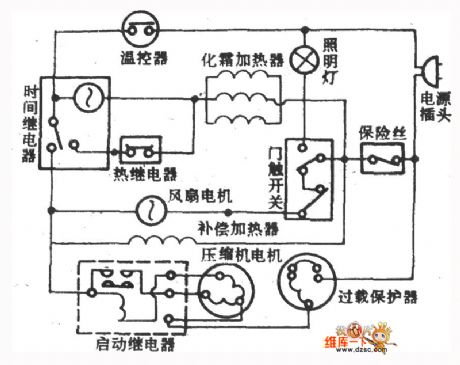
The California SR-190 cool refrigerator circuit is as shown:
(View)
View full Circuit Diagram | Comments | Reading(489)
Infrared Control Water Faucet Circuit Using TX05D
Published:2011/5/1 10:04:00 Author:Robert | Keyword: Infrared Control, Water Faucet
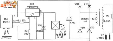
Infrared Control Water Faucet Circuit Using TX05D is shown below:
(View)
View full Circuit Diagram | Comments | Reading(1307)
Infrared Control Circuit
Published:2011/5/2 3:13:00 Author:Robert | Keyword: Infrared Control
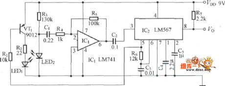
Infrared Control Circuit is shown below:
(View)
View full Circuit Diagram | Comments | Reading(594)
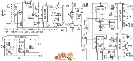
Infrared Control Electronic Dog Circuit Using TX05D
Published:2011/5/2 3:12:00 Author:Robert | Keyword: Infrared Control, Electronic Dog
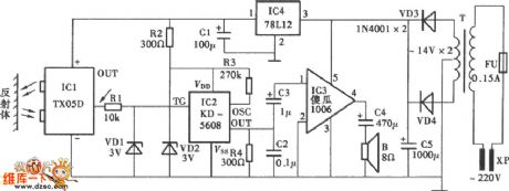
Infrared Control Electronic Dog Circuit Using TX05D is shown below:
(View)
View full Circuit Diagram | Comments | Reading(664)
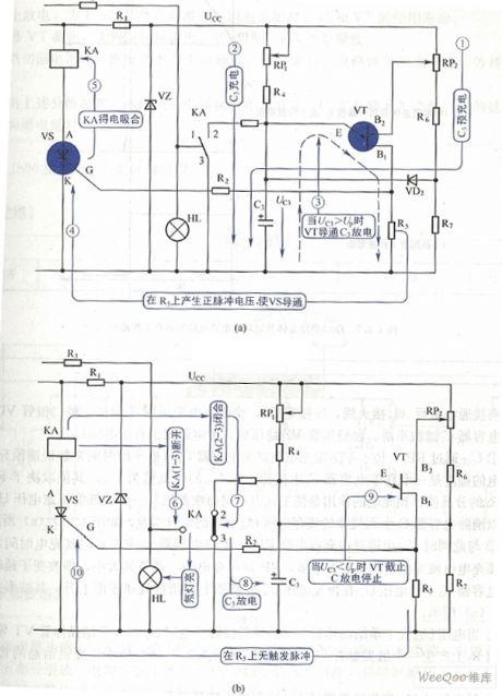
Infrared Delay Lighting Switch Circuit
Published:2011/5/2 4:08:00 Author:Robert | Keyword: Infrared Delay, Lighting Switch
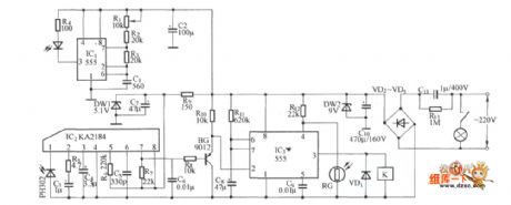
Infrared Delay Lighting Switch Circuit is shown below:
(View)
View full Circuit Diagram | Comments | Reading(671)
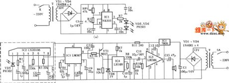
Infrared Control Electronic Ceremonial Speech Device Circuit Using CX20106
Published:2011/5/2 4:06:00 Author:Robert | Keyword: Infrared Control, Electronic Ceremonial Speech Device
Infrared Control Electronic Ceremonial Speech Device Circuit Using CX20106 is shown below:
(View)
View full Circuit Diagram | Comments | Reading(730)
Infrared Detection Electric Shock Protection And Warning Circuit
Published:2011/5/2 4:11:00 Author:Robert | Keyword: Infrared Detection, Electric Shock Protection And Warning
Infrared Detection Electric Shock Protection And Warning Circuit is shown below:
(View)
View full Circuit Diagram | Comments | Reading(1134)
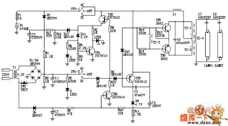
AC/DC Dual-Use Fluorescent Lighting Circuit
Published:2011/5/2 3:17:00 Author:Robert | Keyword: AC/DC Dual-Use, Fluorescent Lighting
View full Circuit Diagram | Comments | Reading(1277)
RP Addition Circuit
Published:2011/5/2 2:53:00 Author:Felicity | Keyword: RP Addition Circuit,
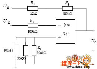
RP Addition Circuit is that several input signals are inputed at the inverting input of integrated operational amplifier. And the output signal is the sumof reversing enlarging proportion. (View)
View full Circuit Diagram | Comments | Reading(590)
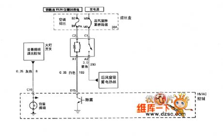
Buick Rega car air condition system GS3.0,GS+ circuit diagram(2)
Published:2011/5/2 7:44:00 Author:Nicole | Keyword: Buick Rega, car, air condition system
View full Circuit Diagram | Comments | Reading(463)
GM Wuling automobile vehicle electrical system circuit diagram
Published:2011/4/29 6:04:00 Author:Rebekka | Keyword: GM Wuling Automobile, Vehicle electrical systems
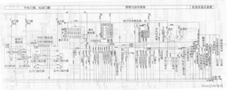
GM Wuling automobile vehicle electrical system circuit diagram. (View)
View full Circuit Diagram | Comments | Reading(1465)
GM Wuling automobile Motorola electronic control system circuit diagram
Published:2011/4/29 6:06:00 Author:Rebekka | Keyword: GM Wuling Automobile, Motorola electronic control system
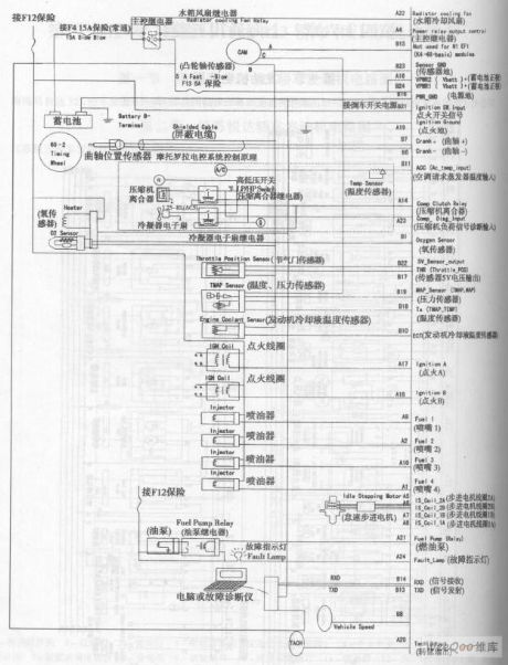
GM Wuling automobile Motorola electronic control system circuit diagram. (View)
View full Circuit Diagram | Comments | Reading(665)
Single-transistor time relay circuit diagram
Published:2011/4/29 5:08:00 Author:Rebekka | Keyword: Single-transistor , time relay
Single-transistor time relay circuit diagram. (View)
View full Circuit Diagram | Comments | Reading(664)
Current source inverter circuit diagram
Published:2011/4/29 5:09:00 Author:Rebekka | Keyword: Current source inverter

Features: L exists. The role of L: filtering and absorption of reactive power for capacitive load. (View)
View full Circuit Diagram | Comments | Reading(3260)
Video amplification circuit composed of discrete device
Published:2011/4/29 4:29:00 Author:Rebekka | Keyword: discrete device, Video amplification
Video amplification circuit composed of discrete device. (View)
View full Circuit Diagram | Comments | Reading(713)
Imbalance test of ground circuit diagram
Published:2011/4/29 4:56:00 Author:Rebekka | Keyword: Imbalance test
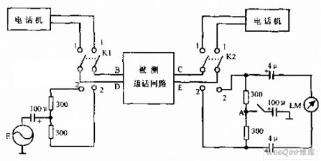
Imbalance test of circuit is shown as below. The output signal E is balance output in the test circuit. LM is the balance indicator, it is tested the talking path. And then the test will be finished.
(View)
View full Circuit Diagram | Comments | Reading(551)
Telephone signals sending circuit diagram
Published:2011/4/29 4:45:00 Author:Rebekka | Keyword: Telephone signals sending
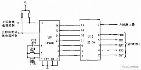
Telephone signals sending circuit is shown as below. U8 is signals sending integrated circuit. The model is 145409. U12 (22100) is a 4X4 cross-matrix circuit (CD22100 is also known as four-way switch). The control circuit is used as U8. (View)
View full Circuit Diagram | Comments | Reading(1483)
High-gain operational amplifier transistor output circuit diagram
Published:2011/4/29 5:04:00 Author:Rebekka | Keyword: high-gain operational, amplifier transistor
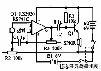
High-gain operational amplifier transistor output circuit diagram is shown as above. Connect the phone Jane to the output of 741. Transistor RS2020 single-tube-driven speaker, R2 is the volume control, R3 can adjust gain and frequency response. (View)
View full Circuit Diagram | Comments | Reading(1090)
Pulse width modulation (PWM) DC motor speed controller circuit diagram
Published:2011/4/29 4:32:00 Author:Rebekka | Keyword: Pulse width modulation , DC motor , speed controller
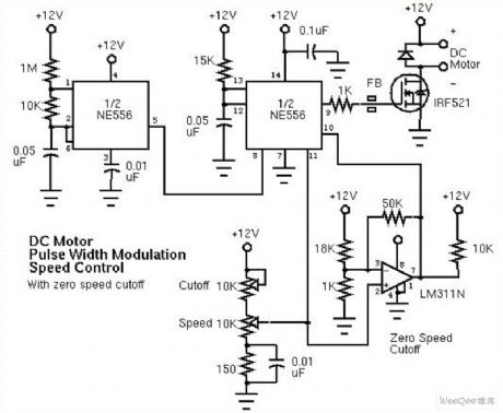
Pulse width modulation (PWM) DC motor speed controller circuit diagram. (View)
View full Circuit Diagram | Comments | Reading(5104)
Reversible DC motor control drive circuit diagram
Published:2011/4/29 4:27:00 Author:Rebekka | Keyword: Reversible DC, motor control drive
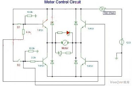
Small DC motor reversible control drive circuit is shown as above. The diode uses 1N4001 series rectifier diode. Two LEDs are mainly used for showing the direction of motor rotation.
(View)
View full Circuit Diagram | Comments | Reading(3509)
| Pages:1975/2234 At 2019611962196319641965196619671968196919701971197219731974197519761977197819791980Under 20 |
Circuit Categories
power supply circuit
Amplifier Circuit
Basic Circuit
LED and Light Circuit
Sensor Circuit
Signal Processing
Electrical Equipment Circuit
Control Circuit
Remote Control Circuit
A/D-D/A Converter Circuit
Audio Circuit
Measuring and Test Circuit
Communication Circuit
Computer-Related Circuit
555 Circuit
Automotive Circuit
Repairing Circuit