
Circuit Diagram
Index 1972
Brightness adjusting circuit diagram composed of LX1970 visible brightness sensor
Published:2011/5/2 22:15:00 Author:Ecco | Keyword: Brightness adjusting , visible brightness sensor
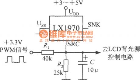
Brightness adjusting circuit is shown as the chart. Adjusting PWM (pulse width modulation) signal duty cycle, you can adjust the backlight brightness to suit individual needs. PWM signal voltage amplitude is 3.3V.
(View)
View full Circuit Diagram | Comments | Reading(826)
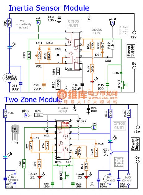
Inertial sensing module circuit diagram
Published:2011/5/2 22:04:00 Author:Ecco | Keyword: Inertial sensing module
View full Circuit Diagram | Comments | Reading(980)
Thermal resistor temperature control refrigeration birdsong phonation circuit
Published:2011/4/29 21:24:00 Author:Nicole | Keyword: thermal resistor, temperature control refrigeration, birdsong
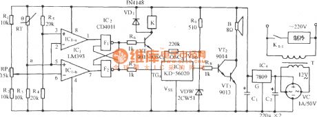
The circuit is as shown, it consists of temperature detection circuit, power ON/OFF detection circuit, relay control motor circuit, birdsong phonation circuit and AC depressurization rectifier circuit. It keeps the temperature of the freezer within the setting temperature range, and it will send out a dulcet small bird sound. (View)
View full Circuit Diagram | Comments | Reading(1205)
Grain and cotton warehouse exaggerated humidity automatic ventilating and language admonishment circuit
Published:2011/4/27 9:16:00 Author:Nicole | Keyword: grain warehouse, cotton warehouse, automatic ventilating, language admonishment
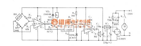
The circuit is as shown, it is composed of humidity sensitivity electric bridge network, comparison circuit, relay control ventilating circuit, language phonation circuit and AC depressurization rectifier circuit . When the warehouse hunidity is exaggerated, the circuit will automatically connect to ventilating fan, and send out admonishment language, to remind the personnel on duty of taking a note. RH is humidity sensor,a bridge testing humidity network is composed of RH, RP1, R1, R2. When the environmental humidity is within the normal range, sensor RH has a large resistance. (View)
View full Circuit Diagram | Comments | Reading(1067)
Shenyang SANYO AC double speed elevator lighting circuit
Published:2011/4/29 4:29:00 Author:Nicole | Keyword: SANYO, double speed stair
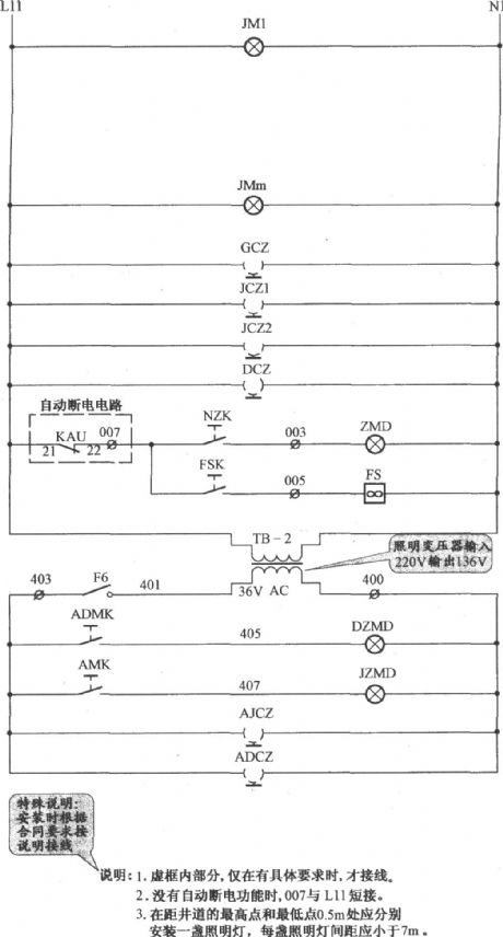
Explanation: 1. The part in gridlines is connected when it has specific requirements. 2. If there is no automatical power off function, 007 is short-circuit to L11. 3. fixing a light on theplace which is 0.5m away from the highest point and the lowest point of the shaft, the space between each light should beshorter than 7m. (View)
View full Circuit Diagram | Comments | Reading(733)
Clock control timing start-up obfuscation guard against theft acousto-optic control circuit
Published:2011/4/29 4:34:00 Author:Nicole | Keyword: clock control, guard against theft, acousto-optic control
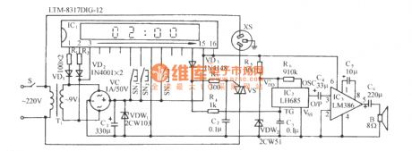
The circuit is as shown. It is composed of clock control timing circuit, SCR control circuit, voice phonation circuit, audio power amplifier circuit and AC depressurization rectifier circuit. This circuit is used for relics exhibition hall, temple, mosque and those occasionsoccasions when nobody is on guard during night. Before the watch keeper leaving,they shouldpreset the clock control time, such as 2:00 am. When it is the preset time, the circuit will light up the indoor lights automatically, and send out noice, to create a false impression that there is someone on duty, then to puzzle the prowler, so that the perpetrator will not rush prematurely. (View)
View full Circuit Diagram | Comments | Reading(774)
Pulse dial display circuit diagram
Published:2011/5/2 21:28:00 Author:Rebekka | Keyword: Pulse dial, display circuit
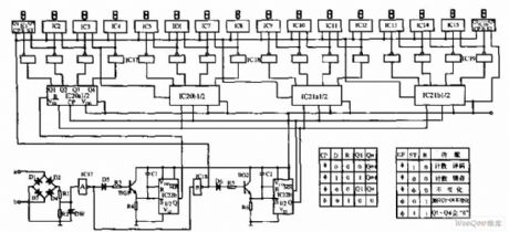
Pulse dial display circuit is shown as below, the circuit is mainly composed of the pulse count (IC1 ~ IC16), differential pulse string (IC22b), shift control (IC20, IC21), 16-bit digital displays and other components. The logic waveforms, timing waveforms are shown as the relevant information. (View)
View full Circuit Diagram | Comments | Reading(899)
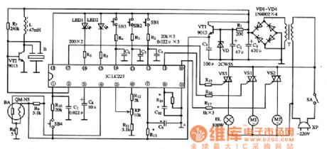
The typical application circuit of LC227 IC
Published:2011/5/2 20:58:00 Author:Ecco | Keyword: typical application circuit, IC
The typical application circuit
The hood control system typical application circuit composed of LC227A integrated circuit is shown as the chart.
The typical application circuit of LC227 IC is shown as the chart.
(View)
View full Circuit Diagram | Comments | Reading(515)
Three key interlock electronic switching circuit diagram
Published:2011/5/2 21:08:00 Author:Rebekka | Keyword: Three key interlock, electronic switching
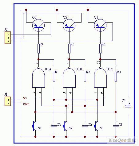
Three key interlock electronic switching circuit diagram. (View)
View full Circuit Diagram | Comments | Reading(1004)
Light beam receiving circuit
Published:2011/4/29 4:43:00 Author:Nicole | Keyword: light beam receiving
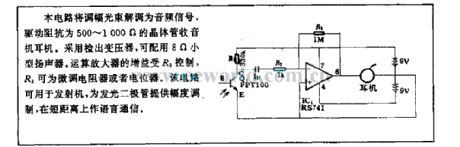
This circuit demodulates amplitude modulation light beam into audio singal to drive the transistor radio earphone with 500~1000Ω resistance. Detection transformer is adopted, and it is served with a 8Ω miniature loudspeaker. The gain of operational amplifier is controlled by R3, R3 is a trimming resistor or potentiometer. This circuit can be used in transmitter, providing LED with amplitude modulation, it also can be used as language communication for a short distance. (View)
View full Circuit Diagram | Comments | Reading(693)
Photosensitive diode circuit used by optical rotary encoder
Published:2011/5/2 6:05:00 Author:Nicole | Keyword: photosensitive diode, optical rotary encoder
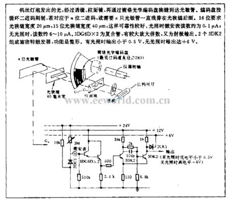
The light which is emitted by tungsten bulb reaches photosensitive tube by lens, cylindrical lens and chromium plating optical coded disc slit. The coded disc is scribed as cyclical binary code, if it is n bits binary code, then it needs n photosensitive tubes arrangement in a straight line behind the light slit. 16 bits requires light slit with 20μm width, 15 bits requires light slit with 40μm width, it has good reliability. When it has light, the ammeter showns 0.1μA; when it has no light, it showns 6~10μA. 3DG6D*2 is composite pipe, it has larger amplification factor, it also is the emitter output. Schmitt trigger is composed of two 3DK2, its function is plastic. When it has light, the output is lower than 0.5V, when it has light, the output can reach +6V. (View)
View full Circuit Diagram | Comments | Reading(1517)
Photosensitive oscillation circuit
Published:2011/4/29 23:16:00 Author:Nicole | Keyword: photosensitive oscillation
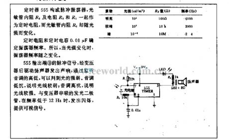
The pulse oscillator is composed of timer 555, the timing resistor consists of photosensitive tube internal resistance R2, resistance R3 and R1, the photosensitive tube internal resistance R2 changes in relation to light intensity.
The oscillator frequency is decided by timing resistor and timing capacitor 0.01μF. So when the light intensity changes, the oscillator frequency changes too.
After transformer drives loudspeaker, the pulse singal of 555 output terminal ③ sends out noise, it can identify the light intensity according to the pitch of monitor tone. If it is low in pitch, then the light is weak; if it is high in pitch, then the light is strong. LED is in series with transformer, when the frequency is lower than 12Hz, it will flash and provide a visible singal. (View)
View full Circuit Diagram | Comments | Reading(602)
Optical coupling SCR circuit
Published:2011/4/29 22:26:00 Author:Nicole | Keyword: Photo coupler, SCR
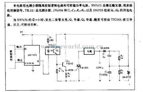
This circuit uses optical coupler to isolate control logic circuit and SCR power circuit. SN7475 is slow trigger, it is used to receive control singal. TIL111 is optical coupler. Q1, Q2 power supply circuit is composed of IN4004, C1, C2, R4, R5 and 1N4733.
When SN7475'S Q=0, LED lights up, Q1 and Q2 turn on, triggering SCR TIC263 to turn on. On the contrary, SCR cuts off. (View)
View full Circuit Diagram | Comments | Reading(2154)
Optical control bolton flash safety light circuit
Published:2011/4/29 22:57:00 Author:Nicole | Keyword: optical control, safety light
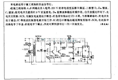
This circuit is suitable for construction site safety light.
In construction site, A, B terminals are connected to power network, 220V mains supply is reduced by transformer B, it is rectified by Dw and filtered by C1, it provides photoelectric switch with 9V DC power. Dw takes the action of rectification and voltage regulation. Under bright light during the day, photoelectric switch cuts off, SCR1 has no trigger current and it is in off state, the red singal indicator light ZD does not turn on. When night comes, photoelectric switch turns on, the oscillation circuit which is composed of IC starts to work, IC's ③ constantly outputs ultra-low frequency rectangular pulse, SCR2 is conduction under this pulse's high level, and it is closed under the low level, so we can see the singal light winking. (View)
View full Circuit Diagram | Comments | Reading(617)
Municipal electric power photoelectric control circuit
Published:2011/5/2 7:41:00 Author:Nicole | Keyword: Municipal electric power, photoelectric control
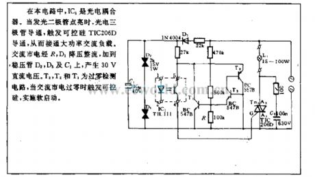
In this circuit, IC1 is photoelectric isolator. When LED is lightened, photoelectric triode turns on, to trigger SCR toturn on, then to connect the high power AC load. AC municipal electric power is added to regulator tube D2, D3 and C1 through R, D1 depressurization rectifier, it will produce 30V DC voltage. T2, T3 are zero-crossing detection circuit, when the AC municipal electric power is zero-crossing, it will trigger SCR to do soft start. (View)
View full Circuit Diagram | Comments | Reading(870)
High-power full-bridge converter circuit diagram
Published:2011/4/22 18:42:00 Author:Nicole | Keyword: full-bridge converter
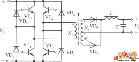
The two electrolytic capacitors of half-bridge converter circuit are changed to the other two high voltage power transistors, and coupled with appropriate drive circuit then can be composed of full-bridge converter circuit, the figure is as shown. VT1, VT2, VT3, VT4 form 4 bridge arms. High frequency transformer T is connected between them. Relative VT1, VT4 and VT2, VT3 alternately inspired by the drive circuit turning on, the DC input voltage into a high-frequency square-wave transform AC voltage. The course of working is the same as push-pull power converter circuit. Thus, when the high frequency transformeris working, the voltage of primary coil is considered to the supply voltage, it is twice the half-bridge circuit output voltage, the pressure of each transistor remains at the supply voltage, twice the output power increases. If the current reach half-bridge circuit, that means the current increases twice, then the output power can increase 4 times. The main disadvantages of full-bridge circuit is thatit needs 4groups transistor base drive circuits which are insulative with each other, complex and increase the cost of the control drive circuit.
(View)
View full Circuit Diagram | Comments | Reading(1122)
Actuation Delaying Relay Circuit
Published:2011/4/25 23:55:00 Author:Joyce | Keyword: Actuation Delaying, Relay
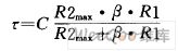
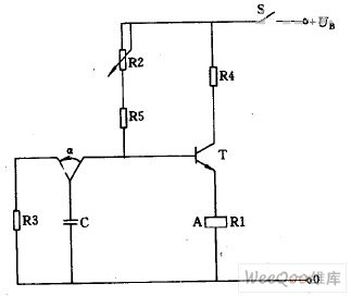
If a delay circuit which is long-lasting and easy to adjust is wanted , then the relay current should be controlled by the transistor, and a RC link should be connected to the basic circuit, as shown in the figure. If power supply voltage, capacitance C, current amplification factor β and the required operation power are known, you should choose the appropriate relay coil resistance and working voltage values, so that delay time could be as long as possible. The length of time can be determined by calculating the time constant :
(View)
View full Circuit Diagram | Comments | Reading(892)
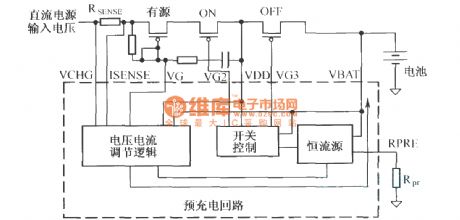
Process of TWL2213 lithium ion battery charging
Published:2011/5/2 7:15:00 Author:Nicole | Keyword: lithium ion battery
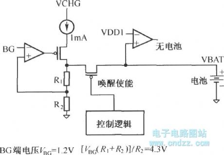
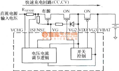
Arousal of Li-ion batteries:
Pre-charge circuit:
Fast charge and termination:
Temperature monitoring:
TWL2213 is monitoring the temperature of lithium ion battery all the time during the charging period, and it uses NTC thermal resistor to produce ADC input reference voltage. TWL2213 will compare ADC reference voltage with programmable threshold voltage, then it will decide to stop the process of charging or over heat cutting. (View)
View full Circuit Diagram | Comments | Reading(714)
ZD—30C and ZD-30D automatic gravimetric filling instrument photo-sensitive circuit
Published:2011/5/2 7:17:00 Author:Nicole | Keyword: automatic gravimetric filling instrument, photo-sensitive
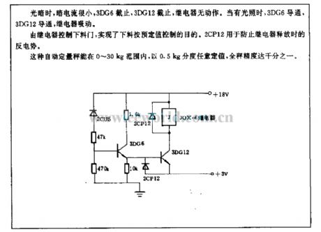
When it is low brightness, the current is small, 3DG6 turns off, 3DG12 turns off, relay has no action. When it has light, 3DG6 turns on, 3DG12 turns on, relay pulls up.
The baiting gate is controlled by relay, it can accomplish the aim of baiting as the desired value. 2CP12 is used to prevent the Back EMF released by relay.
This automatic gravimetric filling instrument can set value with 0.5kg graduation discretionarily in the range of 0~30kg, the precision can reach millesimal. (View)
View full Circuit Diagram | Comments | Reading(1342)
CCCV Lithium Battery Charge Control Schematic Circuit
Published:2011/4/25 23:59:00 Author:Joyce | Keyword: CCCV, Lithium Battery, Charge Control, Schematic
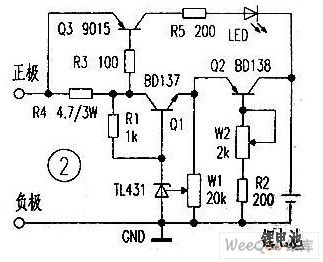
This is a CCCV lithium battery charging control panel.Q1, R1, W1, TL431 in the figure compose a precise and adjustable constant-voltage circuit. Q2, W2, R2 constitute an adjustable constant-current circuit. Q3, R3,R4 ,R5, LED is a battery charging circuit. As the voltage of the charging lithium battery rises gradually, the charging current will decrease . When the battery is filled, pressure drop on the R4 will gradually decrease till Q3 is cut off, and eventually LED would extinguish. In order to ensure adequate charge of the battery , please continue to charge for 1 ~ 2 hours after the light extinguishes , and install cooling fin of proper size in Q2, Q3 when in use. (View)
View full Circuit Diagram | Comments | Reading(3316)
| Pages:1972/2234 At 2019611962196319641965196619671968196919701971197219731974197519761977197819791980Under 20 |
Circuit Categories
power supply circuit
Amplifier Circuit
Basic Circuit
LED and Light Circuit
Sensor Circuit
Signal Processing
Electrical Equipment Circuit
Control Circuit
Remote Control Circuit
A/D-D/A Converter Circuit
Audio Circuit
Measuring and Test Circuit
Communication Circuit
Computer-Related Circuit
555 Circuit
Automotive Circuit
Repairing Circuit