
Circuit Diagram
Index 1980
IR2156 fluorescent lamp integrated circuit electron ballast
Published:2011/4/23 3:36:00 Author:May | Keyword: fluorescent lamp, integrated, electron ballast
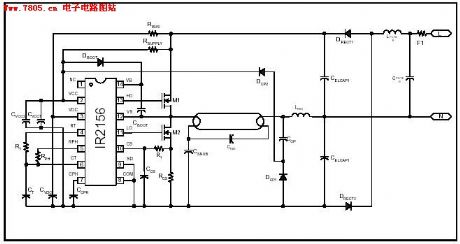
IR2156 can offer solution of high cost-effectiveness for fluorescent electron ballast. It can integrate lighting tube error protection and the programmable working frequency with warm-up, lighting and ballast continue working.
(View)
View full Circuit Diagram | Comments | Reading(2707)
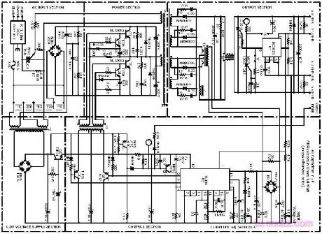
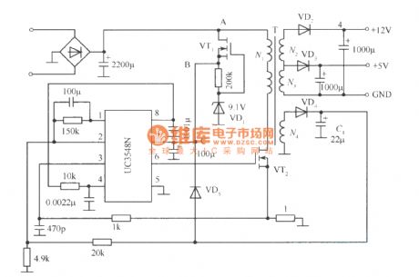
The principle diagram of 400W switchching power output dc5v/80a
Published:2011/4/11 1:03:00 Author:may | Keyword: switchching power, 400W, output dc5v/80a
View full Circuit Diagram | Comments | Reading(802)
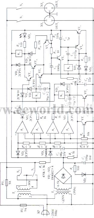
330W AC stabilized voltage supply circuit
Published:2011/4/15 5:34:00 Author:May | Keyword: stabilized voltage supply
View full Circuit Diagram | Comments | Reading(589)
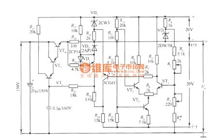
3~120V stabilized voltage supply circuit
Published:2011/4/14 5:58:00 Author:may | Keyword: stabilized voltage supply
View full Circuit Diagram | Comments | Reading(783)
50kHz FM optical receiver circuit
Published:2011/4/15 5:26:00 Author:May | Keyword: FM, optical receiver
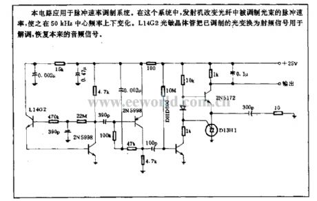
This circuit is used in impulse speed modulation system. In this system, transmitter change impulse speed of modulated beam in optical fiber, let it change around 50kHz center frequency. L14G2 optical transistor convert molulated light to radio-frequency signal. The radio-frequency isusedfor demodulating. It can recover original audio frequency signal.
(View)
View full Circuit Diagram | Comments | Reading(2139)
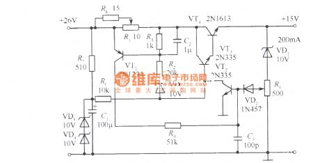
Protective current adjustable 15V stabilied voltage supply
Published:2011/4/15 5:21:00 Author:May | Keyword: Protective current adjustable, 15V, stabilied voltage supply
View full Circuit Diagram | Comments | Reading(584)
Accompanying sound circuit: TDA2616
Published:2011/4/15 5:18:00 Author:May | Keyword: Accompanying sound
TDA2616 pin function and reference voltage:
pin 1: 10V-signal input 1
pin 2: 5V-noise elimination ( low level noise elimination)
pin 3: 10V-1/2 reference voltage
pin 4: 10V-signal output 1
pin 5: 0V-ground
pin 6: 10V-sinal output 2
pin 7: 20V-power supply
pin 8: 10V-negative-going input end
pin 9: 10V-signal input 2 (View)
View full Circuit Diagram | Comments | Reading(693)
Start-up circuit adopts FET
Published:2011/4/14 5:57:00 Author:may | Keyword: Start-up, FET
View full Circuit Diagram | Comments | Reading(625)
Logarithmic amplification circuit
Published:2011/4/2 4:06:00 Author:may | Keyword: Logarithmic amplification
Logarithmic amplification is show in the following picture:
(View)
View full Circuit Diagram | Comments | Reading(685)
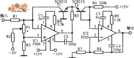
Practical high speed logarithmic amplifier circuit
Published:2011/4/23 1:04:00 Author:May | Keyword: logarithmic amplifier
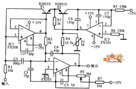
Practical high speed logarithmic amplifier circuit is shown in the following picture:
(View)
View full Circuit Diagram | Comments | Reading(887)
Logarithmic amplifier with temperature compensation circuit
Published:2011/4/23 1:04:00 Author:May | Keyword: logarithmic amplifier, temperature compensation
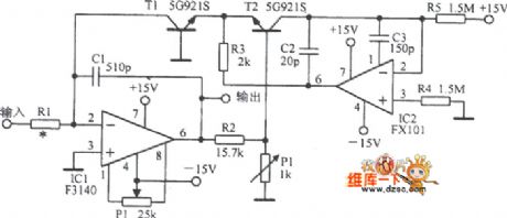
Logarithmic amplifier with temperature compensation circuit is shown in the following picture:
(View)
View full Circuit Diagram | Comments | Reading(2597)
Control and alarm circuit diagram composed of SGZ07 sound and light alarm IC
Published:2011/4/28 22:59:00 Author:Ecco | Keyword: Control , alarm , sound , light, alarm IC
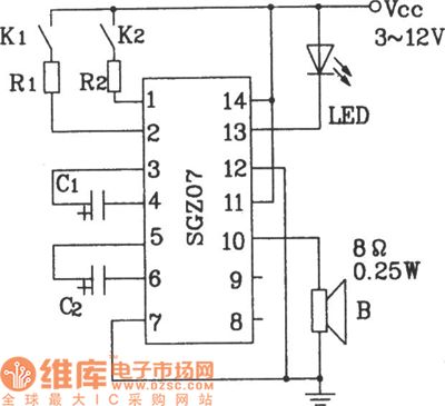
Control and alarm circuit diagram composed of SGZ07 sound and light alarm IC.
In the figure, the circuit can work in dual-band sound, light alarm circuit by controlling the K1, K2. If the R1, R2 in the circuit are changed in the corresponding thermal resistor (measured value), it can achieve temperature control and alarm circuit.
(View)
View full Circuit Diagram | Comments | Reading(924)
Double frequency sound and light source circuit diagram composed of SGZ07
Published:2011/4/28 23:01:00 Author:Ecco | Keyword: Double frequency , sound , light , source , alarm IC

Double frequency sound and light source circuit diagram composed of SGZ07 sound and light alarm IC.
The corresponding relationship between C1, C2 and the output signal.
(View)
View full Circuit Diagram | Comments | Reading(744)
Mashgas, coal gas detection and alarm circuit
Published:2011/4/28 22:56:00 Author:Ecco | Keyword: Mashgas, coal gas, detection , alarm , monolithic, integrated circuit

Mashgas, coal gas detection and alarm circuit composed of CH217 monolithic gas detection alarm integrated circuit.
R1 in the figure is the gas sensing probe, the resistance reduces linearly with gas concentration arbitrarily increasing, RP3 is used to adjust the amplifier output, R6, R7 extract both forecasting and risk reference signal voltage.
(View)
View full Circuit Diagram | Comments | Reading(953)
LED digital salient pole appearance circuit diagram
Published:2011/4/29 0:37:00 Author:Ecco | Keyword: LED , digital, salient pole , appearance
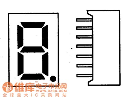
The light-emitting diode display is also known as LED digital display, it uses the feature, which light-emitting diodes will be lit by flowing certain current under forward voltage, the seven segment LED being packaged will become a LED digital display. Its shape is shown as the chart.
(View)
View full Circuit Diagram | Comments | Reading(519)
Two RY927 league level applications circuit diagram
Published:2011/4/28 22:55:00 Author:Ecco | Keyword: Two , league level , application
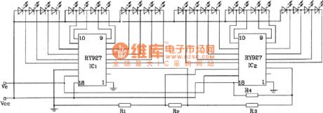
When RY927 is using cascadedly, it needs to connect the related input ends according to the chart. The connecting method is the same when there are more than two stages. It should be noted that RY927 allows seven cascaded as maximum, and it can drive 84 LED at best. Besides the above applications, it can also constitute the automatic dimming, speed tables and so on. If it requires less precision, it can also be used for voltage indication, field instruction and other circuits.
(View)
View full Circuit Diagram | Comments | Reading(587)
The logic pulse generator composing of CD4011
Published:2011/4/18 20:16:00 Author:Ecco | Keyword: logic pulse generator
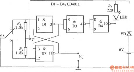
Logic pulse generator can transport either positive or negtive logic pulse according to the need, the circuit is as shown. The circuit consists of a four - two input NAND gate CD4011, of which the door Dl, D2 form a RS trigger pulse, D3, D4 are used as inverters. It isolates the output of D1 and then drives a light-emitting diode after reversing, it is used to indicate the logic state of the output pulse.
(View)
View full Circuit Diagram | Comments | Reading(2804)
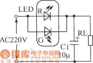
Relay status indication circuit diagram
Published:2011/4/29 1:15:00 Author:Ecco | Keyword: Relay, status indication
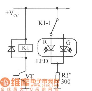
Figure shows the relay status indication circuit. The relay has one or more sets of contacts, If the public end of a group of contacts connects to VDD, the public end will connect to normally closed contacts in releasing state, and LED-R emits red light; the public end will connect to normally open contacts in pulling state, and LED-G emits green light.
(View)
View full Circuit Diagram | Comments | Reading(572)
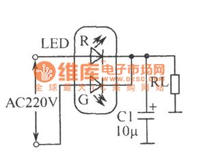
LED full-wave rectifier circuit
Published:2011/4/29 1:16:00 Author:Ecco | Keyword: LED , full-wave , rectifier
View full Circuit Diagram | Comments | Reading(623)
LED half-wave rectifier circuit
Published:2011/4/29 1:19:00 Author:Ecco | Keyword: LED, half-wave , rectifier
View full Circuit Diagram | Comments | Reading(656)
| Pages:1980/2234 At 2019611962196319641965196619671968196919701971197219731974197519761977197819791980Under 20 |
Circuit Categories
power supply circuit
Amplifier Circuit
Basic Circuit
LED and Light Circuit
Sensor Circuit
Signal Processing
Electrical Equipment Circuit
Control Circuit
Remote Control Circuit
A/D-D/A Converter Circuit
Audio Circuit
Measuring and Test Circuit
Communication Circuit
Computer-Related Circuit
555 Circuit
Automotive Circuit
Repairing Circuit