
Circuit Diagram
Index 1974
Power Outage Lighting Circuit With Charging Protection
Published:2011/5/2 2:49:00 Author:Robert | Keyword: Power Outage, Lighting, Charging Protection
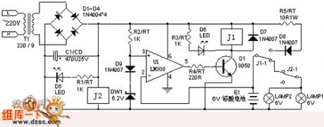

When the power grids have electricity, the comparator U1's + side is referenced voltage 6.9V, if the battery voltage become lower, the u1 would output high voltage level, q1 become conducted, j1 is connected, the battery begin to charging; when the battery voltage rise to the voltage of referenced voltage 6.9V or more, u1 would output low voltage level, which make j1 lost electricity and become disconnected, this achieve auto-charging and protection function. Because of the J2 makes the lamp disconnected, so lamp doesn't light. When the power grids have outage, j1,j2 are all losting electricity and becoming disconnected, so the lamp light.
(View)
View full Circuit Diagram | Comments | Reading(813)
555 Zero-Symmetric Bi-Directional Pulse Generator Circuit
Published:2011/5/1 10:01:00 Author:Robert | Keyword: Zero-Symmetric, Bi-Directional, Pulse Generator
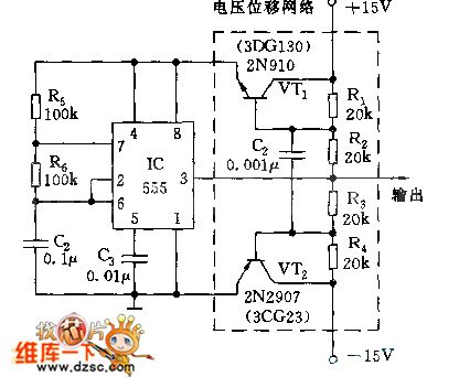
As shown, this circuit can meet the requirements of the periodic pulse outputing symmetrically to the ground.Under the power voltage of +/-15V, it can output +/-11V bi-directional pulse.
VT1, VT2 and R1~R4 make up the voltage shifting networks, using the floating power supply method to the IC 555. 555 and R5, R6, C2 make up the astable multivibrator, oscillation frequency is f=1.44/(R5+2*R6)C2 and it is about 90Hz.
(View)
View full Circuit Diagram | Comments | Reading(1598)
Two-State Touch Light Control Circuit
Published:2011/4/30 19:53:00 Author:Robert | Keyword: Two-State Touch, Light Control
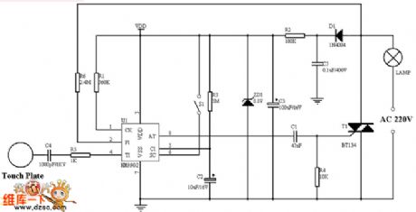
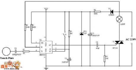
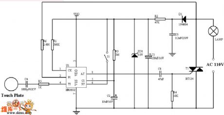
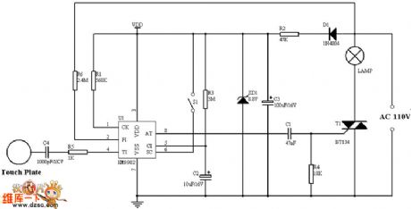
Picture (a) shows the 220V single-wire application circuit.
Picture (b) shows the 220V two-wire application circuit.
Picture (c) shows the 110V single-wire application circuit.
Picture (d) shows the 110V two-wire application circuit.
(View)
View full Circuit Diagram | Comments | Reading(3004)
Transistor storage time test circuit
Published:2011/5/2 5:36:00 Author:Christina | Keyword: Transistor, storage time, test circuit
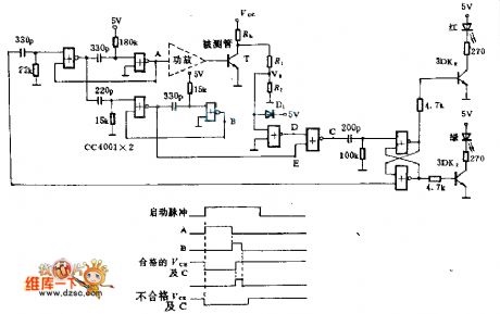
This circuit uses two pieces of CMOSCC4001. If the measure time and the storage time of T is less than the maximum allowable value, the green light turns on, this means qualified; the TS is too large, so the red light turns on, this means unqualified.
Add the pulse to begin testing, point A's pulse width is about 50μS, during the test tube T conducted. Point B's pulse width is about 4μS, this is the T's maximum allowable storage time. If TS<4μS, the C will be 1 , RS flip-flop does not turn, so the red light turns on, green turns off.
(View)
View full Circuit Diagram | Comments | Reading(866)
dimming table lamp circuit
Published:2011/5/2 9:12:00 Author:Christina | Keyword: dimming, table lamp
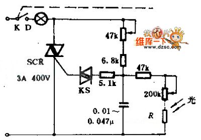
This table lamp can adjust the brightness, and the brightness will not change even if the grid voltage volatility surface changes.
Photosensitive resistor R can be installed on the lamp ornaments, it need the lamp's illumination.
(View)
View full Circuit Diagram | Comments | Reading(524)
Cathode output amp tube circuit
Published:2011/5/2 9:17:00 Author:Christina | Keyword: Cathode output, amp tube
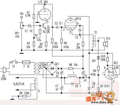
Features of this circuit are the cathode output and the autotransformer, the voltage amplifier stage is very special. This circuit intended to improve the control of amp tube, and to improve the sound clarity.
(View)
View full Circuit Diagram | Comments | Reading(978)
Suzuki GSX400F motorcycle decomposition circuit
Published:2011/5/2 18:41:00 Author:Christina | Keyword: Suzuki, motorcycle, decomposition
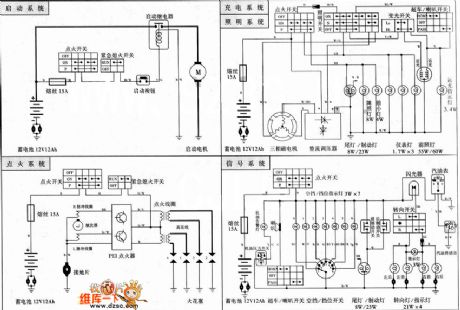
The Suzuki GSX400F motorcycle decomposition circuit is as shown:
(View)
View full Circuit Diagram | Comments | Reading(2261)
Taiwan timing electric heating defrost fridge
Published:2011/5/2 18:38:00 Author:Christina | Keyword: Taiwan, timing, electric heating, defrost
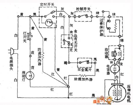
The Taiwan timing electric heating defrost fridge is as shown:
(View)
View full Circuit Diagram | Comments | Reading(555)
CNC lathe test circuit
Published:2011/5/2 19:19:00 Author:Christina | Keyword: CNC, lathe test
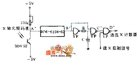
This circuit converts the X-axis's (or Y axis) rotation angle into the optical pulse, and then the photodiode 3DU52 converts the optical signal into electric signal, and outputs the pulse by GD plastic RC circuit to the counter, to achieve closed-loop control system.
(View)
View full Circuit Diagram | Comments | Reading(800)
Temperature Sensor of Current Transmission Circuit
Published:2011/5/1 22:30:00 Author:Felicity | Keyword: Temperature Sensor of Current Transmission Circuit,
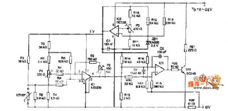
The resistance in the cirtuit is metal film one. Itsaccuracy is better than 1% and temperature coefficient TCis less than ±50X10-6/K.The measuring range is from0℃ to 100℃. Current I= 4+T/6.25. The temperate unit is ℃ and the current unit is mA. The current shows KTY87two-wire current transmitter consisting of Wheatstone bridge with pre-amplifier , current transmitter stage and voltage regulator. (View)
View full Circuit Diagram | Comments | Reading(1013)
Driver Circuit of Bridge Sensor
Published:2011/5/2 2:25:00 Author:Felicity | Keyword: Driver Circuit of Bridge Sensor,
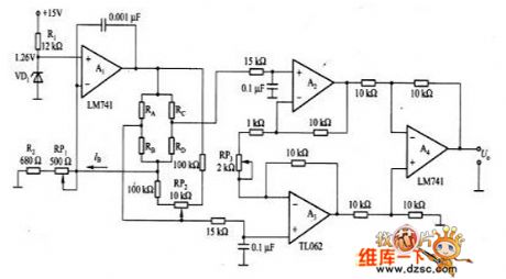
The picture shows the driver circuit of bridge sensor. We can see that in this circuit A1 is the constant current output circuit where the constent value is determined by UZ(the steady voltage of VD1) and (R(RP1)+R2). It provides the patialvalue ofconstant currentto the bridge sensor(the bridge circuit consisting of RA-RD). The amplifier which consisting of A2-A4 can magnify the signals which was outputed by seneors to the level needed. (View)
View full Circuit Diagram | Comments | Reading(671)
Linear Voltage Regulator Composed Microprocessor Power Supply Circuit
Published:2011/5/2 1:42:00 Author:Joyce | Keyword: Linear Voltage Regulator Composed, Microprocessor, Power Supply
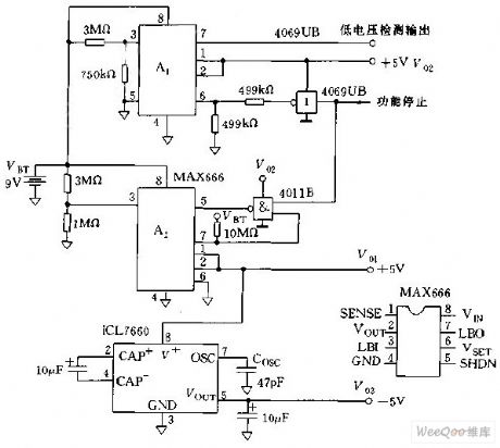
Linear voltage regulators composed microprocessor power circuit is shown in the graph below.It simly consititues of 2 MAX666. Power supply for the CPU and A/D converter is A2,and that for RAM and real-time clock is A1. The output voltage Vo of MAX666 is controlled by VSET , if VSET is connected with GND, the output voltage is 5V,which is fixed. If one uses resistance to part the pressure Vo, the partial voltage will be added to VSET, thus it could be output through programming. (View)
View full Circuit Diagram | Comments | Reading(1144)
LM317-Composed Constant Current and Voltage-stabilized Power Supply Circuit
Published:2011/5/2 2:03:00 Author:Joyce | Keyword: LM317-Composed, Constant Current, Voltage-stabilized, Power Supply
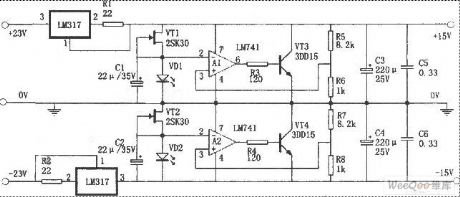
As shown in figure is a constant current and voltage-stabilized power supply connected inparallel,featuring high speed, low noise and low impedance. Using LM317 as its constant current source,it can load constant current up to 560mA . Mosfet 2SR3D and luminotron provide low noise reference voltage. As an error amp,LM741 (amp) would compare and amplify the reference voltage and sampling voltage. In order to stabilize the output voltage,the two 3DD15 are used to adjust the output voltage.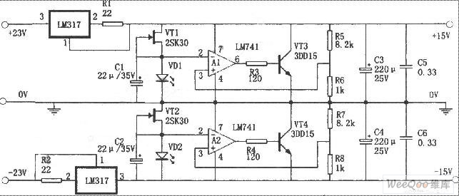 (View)
View full Circuit Diagram | Comments | Reading(4337)
Optocoupler Linear Isolation Amplifier Circuit
Published:2011/5/2 2:22:00 Author:Joyce | Keyword: Optocoupler, Linear, Isolation Amplifier

Optocoupler linear isolation amplifier 3650Features:balanced input;high common-mode voltage, 2000V in a row; high common-mode rejection ratio, 140dB;small leakage of electricity ,less than 0.35 μΑ in 240V/60Hz; high gain accuracy, linearity of0.05%, long-time stability,0.05%/1000 hours; the frequency band 15kHz.Applications: industrial process control, data acquisition system, biomedical measurement, silicon-controlled management. The graph is the wiring paragram in application,with a 722 DC/DC converter in use. (View)
View full Circuit Diagram | Comments | Reading(2889)
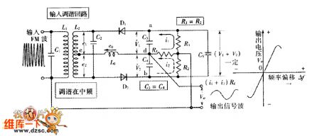
Series Inductance Circuit
Published:2011/4/30 19:43:00 Author:Robert | Keyword: Series Inductance

The most simplest open absorbing circuit is thatthe inductance Lv connects to the switchingtubein series, which shows in picture (a). Picture(b) and (c) separately shows the uv, iv and P curve of the opening process. This illustrates thatafter adding series inductance, it limits the switching tube current's uprising speed , and decrease the power dissipation of the switch.
(View)
View full Circuit Diagram | Comments | Reading(560)
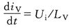
PWM Current Control Circuit
Published:2011/5/2 2:29:00 Author:Felicity | Keyword: PWM Current Control Circuit,
View full Circuit Diagram | Comments | Reading(1032)
Current Control Circuit of Differential Amplifier
Published:2011/5/2 2:38:00 Author:Felicity | Keyword: Current Control Circuit of Differential Amplifier,

View full Circuit Diagram | Comments | Reading(637)
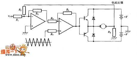
Ratio Detection Circuit
Published:2011/5/1 21:48:00 Author:Felicity | Keyword: Ratio Detection Circuit
View full Circuit Diagram | Comments | Reading(880)
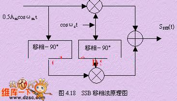
Basic Circuit Diagram of SSB Phase-shift
Published:2011/5/1 22:32:00 Author:Felicity | Keyword: Basic Circuit Diagram of SSB Phase-shift,
View full Circuit Diagram | Comments | Reading(701)
Taiwan hot gas defrost fridge (jet) interval-cool fridge circuit
Published:2011/5/2 8:52:00 Author:Christina | Keyword: Taiwan, hot gas, defrost, jet, interval-cool

The Taiwan hot gas defrost fridge (jet) interval-cool fridge circuit is as shown:
(View)
View full Circuit Diagram | Comments | Reading(1530)
| Pages:1974/2234 At 2019611962196319641965196619671968196919701971197219731974197519761977197819791980Under 20 |
Circuit Categories
power supply circuit
Amplifier Circuit
Basic Circuit
LED and Light Circuit
Sensor Circuit
Signal Processing
Electrical Equipment Circuit
Control Circuit
Remote Control Circuit
A/D-D/A Converter Circuit
Audio Circuit
Measuring and Test Circuit
Communication Circuit
Computer-Related Circuit
555 Circuit
Automotive Circuit
Repairing Circuit