
Circuit Diagram
Index 1981
Optical coupling silicon-controlled switch circuit diagram
Published:2011/3/30 22:58:00 Author:Ecco | Keyword: Optical coupling, silicon-controlled switch
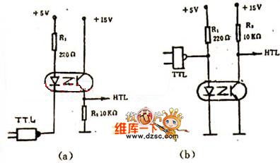

The figure 1(a) shows the optical coupling silicon-controlled switch circuitry. The trigger voltage of silicon-controlled rectifier(SCR) is from resistance R, and the the value is decided by the current of phototriode, controlled by input voltage. The circuitry is simple, and there is reliable electronic isolation between the input and output.
The figure 1(b) shows the switching circuitry in which load controll is pure resistance. And the value of R1 in the figure is decided by the formula as below: R1=V/1.2A,1.2A is bidirectional switching rated current. When the voltage of main network is 220V, V=/2·220=308V,then R1=308/1.2=250Ω. So the specification of silicon-controlled rectifier(SCR) is chosed according to the the value of R1.When the load of switching circuitry is inductive, it needs to increase corresponding components to promise the circuitry's normal work, as the current passing the inductive is different from the phase of voltage. It is shown as below: The switching circuitry shown in the figure 2 is especially suitable for distant control.
(View)
View full Circuit Diagram | Comments | Reading(1324)
MITSUBISHI Pajero light off-road vehicle four-wheel drive indication, loudspeaker, roof motor basic circuit diagram
Published:2011/4/29 1:10:00 Author:Nicole | Keyword: MITSUBISHI Pajero, light off-road vehicle, four-wheel drive, loudspeaker, roof motor

68-ignition switch; 98-high low-grade indicator light switch; 99, 100-two-wheel drive indicator light; 101, 102-four-wheel drive indicator light relay; 104-four-wheel drive switch; 105, 106-electric horn; 107-horn button; 114-roof motor switch; 115-roof motor controllor; 116-roof motor.
(View)
View full Circuit Diagram | Comments | Reading(1474)
Single valve direct radio circuit diagram
Published:2011/3/30 22:14:00 Author:Ecco | Keyword: Single valve , direct radio
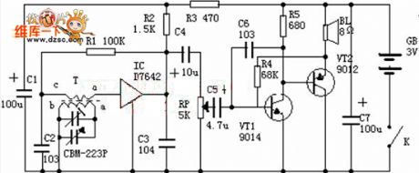
Input tuning loop: It is consisted of magnetic aerial T and 2 changeable capacitance, and its function is receiving electromagnetic wave and choosing broadcasting station. High frequency amplification and demodulation: The TA7642 is a miniature integrated circuit, the shape is similar to the triode which is shown as chart. There are 10 triodes, including third stage high amplifier, one stage demodulation and one stage. Low frequency amplification: The low frequency amplification is completed by two triode VT1, VT2 to hit the speaker of collecting electrode connecting, which converts the low frequency current as sound, the potential machine RP is used as controlling volume. (View)
View full Circuit Diagram | Comments | Reading(4215)
MITSUBISHI Pajero light off-road vehicle instrument alarm lamp basic circuit diagram
Published:2011/4/29 0:56:00 Author:Nicole | Keyword: MITSUBISHI Pajero, light off-road vehicle, instrument alarm lamp
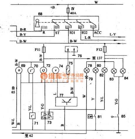
65-ignition coil; 68-ignition switch; 69-tachometer; 70-thermometer; 71-thermometer sensor; 72-fuel gauge; 73-fuel gauge sensor; 74-speedometer; 75-dry reed relay; 76-diffusion detection socket; 77-vehicle speed sensor; 78-charging indicator; 79-diode; 80-oil pressure warning lamp; 81-oil pressure alarm switch; 83, 84-brake parking warning lamp; 85-brake parking switch. (View)
View full Circuit Diagram | Comments | Reading(2289)
MITSUBISHI Pajero light off-road vehicle power supply start-up, ignition circuit basic circuit diagram
Published:2011/4/29 1:03:00 Author:Nicole | Keyword: MITSUBISHI Pajero, light off-road vehicle, power supply start-up, ignition circuit
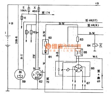
1-storage battery; 59-starter; 60-resistor; 61-diode; 62-integral alternator; 63-added resistance; 64-fuel oil cut-off electromagnetic valve; 65-ignition coil; 66-distributor; 67-spark plug; 68-ignition switch; 69-tachometer; 174-taillight relay. (View)
View full Circuit Diagram | Comments | Reading(1895)
QiSheng DVD-8829 switching power supply circuit diagram
Published:2011/4/11 4:11:00 Author:Rebekka | Keyword: Singular sound , switching power supply

Here is the schematic diagram of theQiShengDVD-8829 switching power supply circuit:
(View)
View full Circuit Diagram | Comments | Reading(5051)
integrated block internal box circuit
Published:2011/4/29 0:50:00 Author:TaoXi | Keyword: integrated block, internal box circuit
1.Features
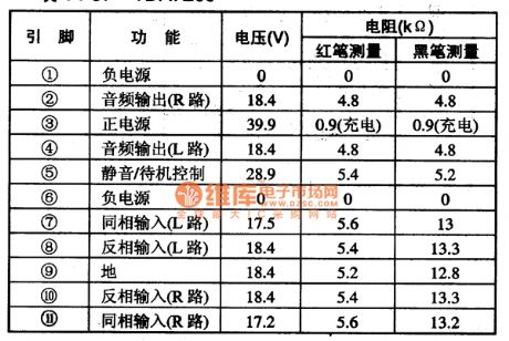
The output power of TDA7265 is 25W per channel; operating supply voltage range is ±25V, also it has the mute and standby functions. This device has the two channels audio power amplifier IC, the over-current protection circuit, the thermal protection circuit and other circuits.
2.Pin functions and data
The integrated block internal box circuit of the TDA7265 is as shown in figure 23, this ic is in 11-pin single in-line package, the pin functions and data is as shown in table 137.
(View)
View full Circuit Diagram | Comments | Reading(705)
Stereo headphone frequency response tester circuit
Published:2011/4/29 0:49:00 Author:TaoXi | Keyword: Stereo headphone, frequency response tester
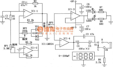
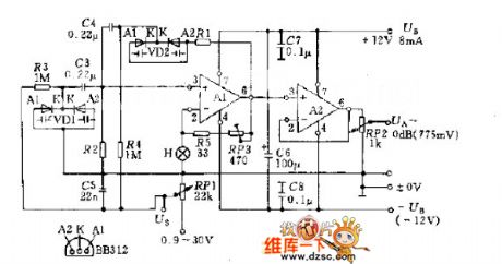
The stereo headphone frequency response tester circuit is as shown in the figure, IC1 is the general-purpose four op amp LM324, the Wien bridge sine wave generator is composed of the IC1-1 and IC1-2; amplifier IC1-3, IC1-4 are the voltage follower. The positive feedback circuit of Wien bridge sine wave generator is composed of the C2、R2 and C1, (R1+RP1), the negative feedback circuit is composed of the R3and R5. One of the greatest feature of this circuit is that the general Wien bridge sine wave oscillator (R1+RPl) is usually grounded, but this (R1+RPl) connects to the IC1-2 invert input port's virtual location. The stable-width circuit is composed of the VDl, VD2 and RP2, in the oscillation process, VDl, VD2 alternately turns on, when the amplitude increases, the negative feedback increases too. And it limits the amplitude continues to increase; and vice versa. Adjust the RPI can make the oscillation frequency between 100Hz~125kHz. (View)
View full Circuit Diagram | Comments | Reading(2193)
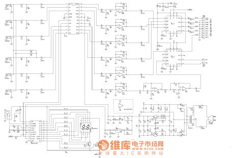
5.1-channel amplifier system circuit diagram
Published:2011/4/29 0:51:00 Author:Ecco | Keyword: 5.1-channel, amplifier system
View full Circuit Diagram | Comments | Reading(10277)
TDA16846 integrated block typical application circuit
Published:2011/4/29 0:50:00 Author:TaoXi | Keyword: integrated block, typical application circuit
TDA7088T--Electric tuning single chip FM radio IC
The TDA7088T is designed for the top-grade thin micro-radio which is produced by the PHILIPS company. It can be used in the gift card radio, the solar cap-radio, the matchbox-radio.etc.
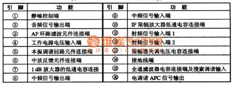
1.TDA16846 integrated block internal box circuit and pin functions
The TDA16846 integrated block internal box circuit is composed of the mixer circuit, the LO circuit, the IF amplifier and limiter circuit. The integrated block internal box circuit and pin functions is as shown in figure 22. This IC is in the dual flat 16-pin mini-SMT package, the pin functionsare as shown in table 36.
TDA16846--Switch power supply control IC
The TDA16846 is designed as one kind of switch power supply control IC which is produced by the PHILIPS company, it can be used in Konka TVs.
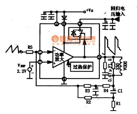
1.Features
The TDA16846 has the dual voltage regulator control circuit, the over-zero detection / error voltage control circuit, the drive output circuit, the over-voltage comparator.etc. The TDA16846 integrated block typical application circuit is as shown in figure 35, the typical application circuit is as shown in figure 36.
(View)
View full Circuit Diagram | Comments | Reading(703)
TDA8177F integrated block internal box circuit
Published:2011/4/29 0:51:00 Author:TaoXi | Keyword: integrated block, internal box circuit
TDA6103Q--Single-chip video magnification integrated circuit
The TDA6103Q is designed as one kind of Single-chip video magnification integrated circuit which is produced by the PHILIPS company, and it can be used in the large screen color TV.
1.Features
The TDA6103Q has the three-way (R, G, B) color signal amplifier to replace the traditional three-way discrete components of the video amplifier.
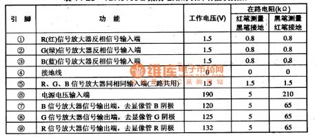
2.Pin functions and data
The TDA6103Q is in the 9-pin single row package, the pin functions and data is as shown in table 14-28.
Table 14-28 The pin functions and data of TDA6103Q
(View)
View full Circuit Diagram | Comments | Reading(670)
Separate-excited Crossed Multivibrator Circuit
Published:2011/4/28 5:17:00 Author:Sue | Keyword: Separate-excited, Crossed, Multivibrator
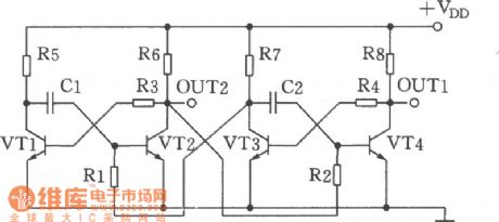
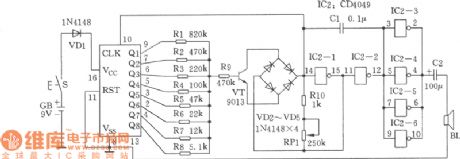
As seen in the figure is the separate-excited crossed multivibrator. It has 2 or 4 kinds of split-phase output waveforms, and can easily get split-phase square wave of 0°、-90°、-180° and 270°. It is simplified with good waveform output, and has no old design including dividing frequency, counting and coding circuit. It is applicablein circuit of phase generator, quad cycled colored lights controller and so on. (View)
View full Circuit Diagram | Comments | Reading(527)
Multitone Sound Imitation Generator Circuit
Published:2011/4/28 5:20:00 Author:Sue | Keyword: Multitone, Imitation, Generator
View full Circuit Diagram | Comments | Reading(589)
Variable pulse width pulse generator circuit
Published:2011/3/23 20:35:00 Author:may | Keyword: pulse generator
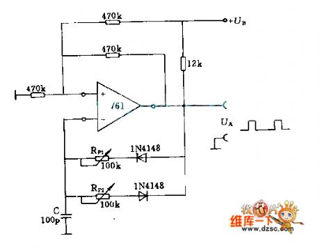
Pulse frequency depends on the size of the capacitance C, according to need can use 0.1uF or other value. 12KΩ resistance is load resistor required by operational amplifier open collector.
(View)
View full Circuit Diagram | Comments | Reading(1615)
Sine oscillating circuit diagram
Published:2011/3/23 20:03:00 Author:may | Keyword: Sine oscillating
The diagram is circuit which consists of VD1, VD2 two variable capacitance diodes, its oscillation frequency is concerned with R1、VD1-R2、VD2, in order to adjust frequency range, the capacitances and resistances of two Bridge road branchs must change the same value of number at the same time. So need to use coaxial connecting two potentiometer or duplex capacitors.
(View)
View full Circuit Diagram | Comments | Reading(636)
Capacitive sensor signal disposal device CS2001 typical application circuit
Published:2011/3/23 4:51:00 Author:may | Keyword: Capacitive sensor signal disposal device
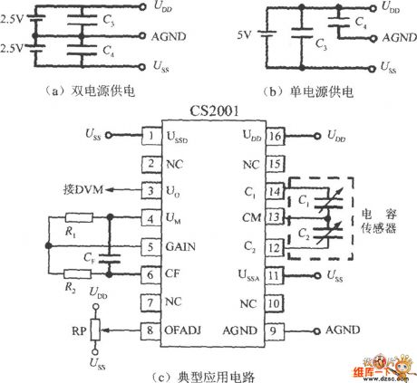
Capacitive sensor signal disposal device CS2001 typical application circuit is shown in the following diagram:
(View)
View full Circuit Diagram | Comments | Reading(785)
MITSUBISHI Pajero light off-road vehicle turn and danger signal, reversing lamp basic circuit diagram
Published:2011/4/28 22:59:00 Author:Nicole | Keyword: MITSUBISHI Pajero, light off-road vehicle, reversing lamp, danger signal, turn signal
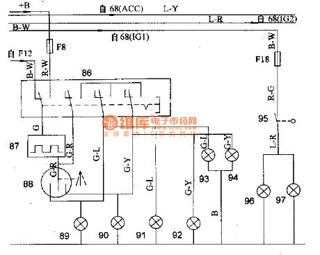
68-ignition switch; 86-dangerous alarm switch; 87-turn signal and dangerous alarm flasher; 88-steering lamp switch; 89, 91-left trun signal lamp; 90, 92-right trun signal lamp; 93-left trun indicator light; 94-right trun indicator light; 95-reversing lamp switch; 96, 97-reversing lamp. (View)
View full Circuit Diagram | Comments | Reading(1428)
High voltage following circuit diagram
Published:2011/4/28 22:34:00 Author:Ecco | Keyword: High voltage , following
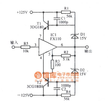
High voltage following circuit diagram is shown as the chart. (View)
View full Circuit Diagram | Comments | Reading(545)
VIOS car door lock control circuit diagram
Published:2011/4/28 22:26:00 Author:Ecco | Keyword: VIOS , car door lock , control
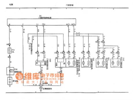
VIOS car door lock control circuit diagram is shown as the chart. (View)
View full Circuit Diagram | Comments | Reading(2447)
Audi A6 front seat heating system circuit diagram
Published:2011/4/28 22:28:00 Author:Ecco | Keyword: Audi , front seat , heating system
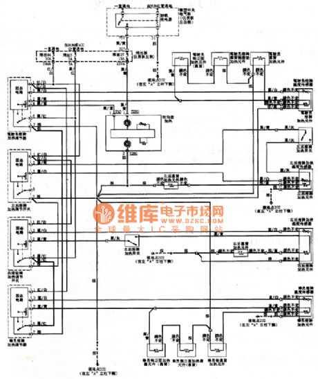
Audi A6 front seat heating system circuit diagram is shown as the chart. (View)
View full Circuit Diagram | Comments | Reading(1361)
| Pages:1981/2234 At 2019811982198319841985198619871988198919901991199219931994199519961997199819992000Under 20 |
Circuit Categories
power supply circuit
Amplifier Circuit
Basic Circuit
LED and Light Circuit
Sensor Circuit
Signal Processing
Electrical Equipment Circuit
Control Circuit
Remote Control Circuit
A/D-D/A Converter Circuit
Audio Circuit
Measuring and Test Circuit
Communication Circuit
Computer-Related Circuit
555 Circuit
Automotive Circuit
Repairing Circuit