
Circuit Diagram
Index 1992
Intermediate frequency signal generator made by 3L465 ceramic filter
Published:2011/4/24 22:32:00 Author:Ecco | Keyword: Intermediate frequency , signal generator, ceramic filter
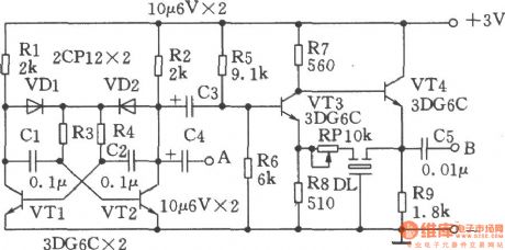
Figure shows the intermediate frequency signal generator made by 3L465 ceramic filter, the line is simple, easy to start up, the resulting IF signal is stable, it has a good repeatability and outputs audio signal. Working principle: VTl, VT2 and related components form a multivibrator with frequency in 400Hz, it is used to modulate IF signal, audio signal can be output from the A point. VT3, VT4 form an IF signal generator, DL has the selected frequency effect. RP can change the oscillation intensity adjustment. Leading a wire of a few centimeters in B point to output modulated IF signal. Multivibrator can work when getting power if welding is correct. The inspection part of the IF signal generator circuit is correct, it can use a medium-radio to close to the B point leading wire, adjusting the RP make the radio receive the signal, then the adjustment is end. When using, the radio wave band switch should be put at medium wave, the variable capacitor is adjusted to the the low-spin, and then point B closing to the AM ferrite antenna coil lead wire, and then one by one repeatedly adjusting the frequency transformer make the speaker's voice or added to voltage be the maximum.
(View)
View full Circuit Diagram | Comments | Reading(1311)
2100Hz signal generator
Published:2011/4/22 2:13:00 Author:Ecco | Keyword: 2100Hz, signal generator
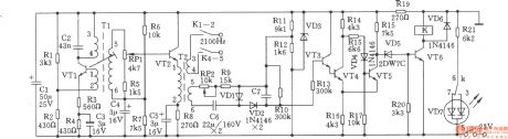
When 2100Hz output level is lower than normal level 3.5dB, the both ends voltage of C7 is about 3.4V and couldn't reach the trigger value, so VT4 stopd, VT5 is conducted. Thus VD5 and VT6 close, relay K loses electricity and releases, contacts K1-2, K8-9 are off, K8-9 is closed. No 2100Hz signal outputs, light-emitting diode VD7 displays a red warning signal. Potentiometer could adjust the action level value of relay K RP2. Component selection: VTl, VT3, VT4, VT5: 3DG6C, β = 50 ~ 115, VT2, VT6: 3DGl28, β = 85 ~ 115. Double color LED VD7: BT a 605 (red, green and white). Relay K: PR401-1250Ω. Oscillation transformer Tl: L1-2 is Φ0.11mm high-strength wire with 37 turns, L3-4 is 0.11mm with 713 turns, L5-6 is 0.1lmm high-strength wire with 358 turns. It uses tank-type ferrite with model in MTT22. Output transformer T2: L1-2 is Φ0.11mm high-strength wire with 141 turns, L3-4 is Φ0.12mm with 43 turns, L5-6 is Φ0.12mm with 177 turns. It uses tank-type ferrite with model in MTT22. The resistor selects the 1/4W 1/8W metal film resistor.
(View)
View full Circuit Diagram | Comments | Reading(688)
Five functions refrigerator protection(CD4060,C043,C033)
Published:2011/4/26 4:07:00 Author:Ecco | Keyword: Five functions, refrigerator, protection
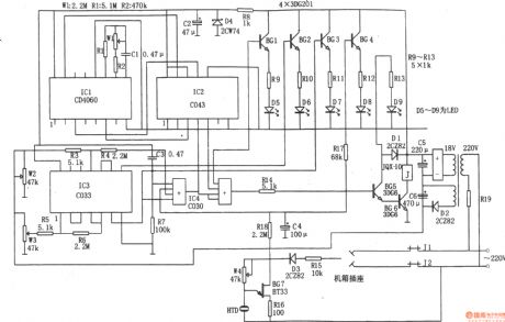
The circuit shown as the chart is the five functional refrigerator protection circuit. The protection is composed of the time base signal generator, power voltage monitoring circuit, shaping circuit, the electrical control circuit, leakage alarm circuit. The time base signal generator is composed of IC1 (CD4060) and R1, R2, W1, C1 and so on. It can produce 3 kinds of time signals with 5 minutes and 40 seconds, 22 minutes and 30 seconds and 12 hours, time signals is combined by the IC2 (C043) logically, the output from the IC2 ⑨ feet every 12 hours 22 minutes and 30 seconds defrost time can control signal. Supply voltage monitoring circuit is composed of the IC3 (C033) and W2, W3, R5, R6, etc., of which W2, W3, respectively are the up and down limit preset potentiometers. When the grid voltage changes in the range of 175 ~ 245V, IC3 ⑥, ⑧ feet are 0V, no control signal is output. When the grid voltage falls below 175V, IC3 ⑥ pin outputs control signal. When the grid voltage is above 245V, IC3 ⑧ feet outputs control signals. Leakage alarm circuit is composed of the BG7, D3, HTD, W4 and so on. In case of leakage, the leakage current flowing through D3 is rectified to make BG7 oscillations, it drives piezoelectric HTD to make alarm sound.
(View)
View full Circuit Diagram | Comments | Reading(2179)
Auto counter for producivity 3
Published:2011/4/25 21:13:00 Author:Ecco | Keyword: Auto counter , producivity
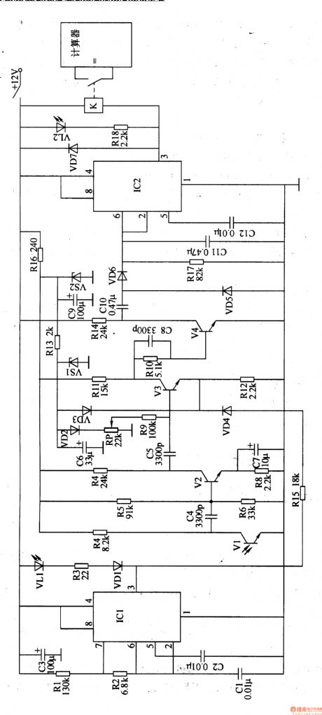
The auto counter for productivity described in the example uses infrared reflection control circuit, it can be used for automatic counting of a variety of assembly line production.
The working principle.
The auto counter for productivity circuit is composed of infrared emission circuit, infrared receiver processing circuit, voltage rectifier circuit, control implementation circuit and the count display circuit, it is shown in Figure 8-83.
Infrared transmitter circuit consists of infrared light-emitting diode VLl, resistors Rl-R3, diode VDl, capacitors CI-C3 and the time-base integrated circuit ICl.
Infrared receiver processing circuit is composed of the infrared phototransistor Vl, transistor V2-V4, resistors R4-R16, capacitors C4-C9, voltage regulator diode VSl, VS2, and potentiometer RP.
Doubler rectifier circuit is composed of the capacitor ClO and Cll, diodes VD5, VD6 and resistors R17.
The control implementation circuit is composed of time base control circuit IC2, resistor R18, diode VD7, capacitor Cl2, light-emitting diodes VL2 and relays K.
(View)
View full Circuit Diagram | Comments | Reading(526)
Automatic hand dryer circuit diagram
Published:2011/4/22 3:41:00 Author:Ecco | Keyword: Automatic, hand dryer
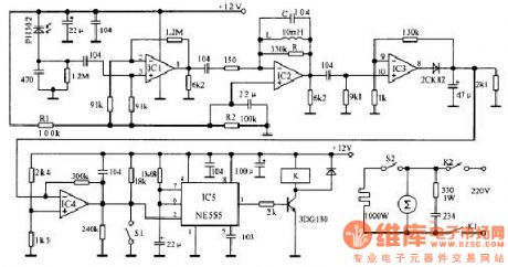
Infrared emission part generates a square wave signal with 50% duty cycle and 5kHz frequency by 555 circuit. And the signal drives the red launch tube to emit the infrared ray.
When the hand placed under the dryers, as the hand has the reflecting effect to infrared ray, the PH302 in receiver circuit will receive the infrared signal change it into electrical signal, and it passes the selected frequency amplifier composed of IC1, IC2, IC3, the output signal being a DC signal and gets into the comparator IC4 by amplified, shaped, filtered. Comparator threshold voltage is 7V, setting high aims to improve the circuit's noise immunity. When IC4 input level exceeds 7V, the output goes low, the rocks make IC5 timer start timing, while 3 feet of the timer goes high to make 3DG130 turn, pull-point of relay pulls in to connect to resistance wire. (View)
View full Circuit Diagram | Comments | Reading(5465)
56M video images transmitting circuit diagram
Published:2011/4/18 1:03:00 Author:Rebekka | Keyword: transmitting circuit, 56M video images
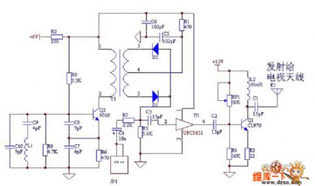
The RF Circuits produce 56MHz frequency through colpitts feedback. The image signal passes camera collection and the internal circuit turns to analog voltage signal. It output from JP1 to diode mixer circuit, mixing circuit will mix the analog voltage signal output by camera with LO signal to form radio-frequency signal. The radio-frequency signal that is amplified by uPC1651 integrated operational amplifier and total emitter circuit will be posted. uPC1651 is TV antenna amplifier ASIC. It is a ultra-high frequency, wide band(Frequency bandwidth of 1200MHz), low noise, large power gain(19dB,f=500MHz), high frequency linear amplifier. (View)
View full Circuit Diagram | Comments | Reading(569)
Winding machine electronic counter 1
Published:2011/4/25 21:29:00 Author:Ecco | Keyword: winding machine , electronic counter
The winding machine electronic counter described in the example has the function of addition, subtraction automated counting, it can be used for transformers, motors, manufacturers restructuring the use of a variety of common winding machine.
The working principle.
The winding machine electronic counter is composed of photoelectric sensor circuit, shaping circuit, plus / minus four-digit identification circuit and counter circuit, it is shown in the figure 8-84.
Photoelectric sensor circuit consists of resistors Rl, R2, R8, R9, and, and optocouplers VLCl, VLC2.
RI, R8 and VLC1 form an addition counting sensor circuit.
R2, R9 and VLC2 sensor form a subtraction count circuit.
Shaping circuit consists of the Dl-D4 inside the six non-gate Schmitt trigger circuit ICl.
Plus / minus identification circuit is composed of the A1,A2 inside the double-D flip-flop IC2.
Four digits counter is composed of the resistors R3-R7, reset button S, counter / decoder IC lC3-1C6 and LED digital display A-D. (View)
View full Circuit Diagram | Comments | Reading(2941)
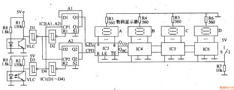
Winding electronic counter 2
Published:2011/4/25 21:39:00 Author:Ecco | Keyword: Winding , electronic counter
The winding machine electronic counter described in the example uses LED digital display to show the wound coil turns, the use of maximum count rate is 9900 turns.
The working principle
The winding machine circuit is composed of the power circuit, infrared switch circuit, shaping / transformation circuit, reset circuit, divider circuit and the LED counter circuit, it is shown in Figure 8-85.
Power circuit is composed of the power transformer T, rectifier bridge pile UR, filter capacitor C4 and the three-terminal voltage regulator integrated circuit ICl.
Infrared switch circuit consists of infrared light-emitting diodes VL, infrared phototransistor V and resistors Rl and R2.
Plastic / converter integrated circuit is composed of the time base circuit IC2 and resistor R3, capacitor Cl and C2.
The reset circuit is composed of reset button SI, resistors R4, R5 and capacitor C3.
Count divider circuit consists of integrated circuits IC5, 1C6, and override switch S2, S3. LED LED digital display is composed of the counter circuit A & B, resistor R6-Rl9 and counter / decoder integrated circuit IC3, 1C4. (View)
View full Circuit Diagram | Comments | Reading(2002)
Metal detector 5
Published:2011/4/26 4:58:00 Author:Ecco | Keyword: Metal detector
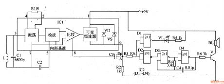
The working principle.The metal detector circuit is composed of sound and light alarm oscillator circuit, it is shown in Figure 8-71.
Oscillator circuit consists of inductor L, capacitor Cl, sensor switch integrated circuit ICl (includes oscillator, detector and comparator circuit, etc.) and the peripheral components. Sound and light alarm circuit consists of four NOR gate integrated circuit lC2 (Dl-D4) and light emitting diode VL, speaker BL and other components. When the inductor (detection coil) L detecting metal objects, the oscillator circuit oscillation, the loss is smaller, the pin 6 of ICl outputs low level, sound and light alarm circuit is not working, VL LED is not lit, the speaker BL does not ring.
When the L detecting metal objects, the oscillator stops, pin 6 of IC1 changes into high level from low level, the DI and D2 inside NOR gate integrated circuit IC2 output low level, the light-emitting diode VL is lit; while enabling the audio oscillator composed of NOR gate D3, D4 and resistor R4, capacitor C4 works, it produces audio oscillator signal which is amplified by the V to drive the speaker BL alarm, and the sound will indicate the user they have detected metal objects. (View)
View full Circuit Diagram | Comments | Reading(2119)
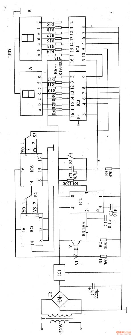
FR series of LED digital display shape circuit diagram
Published:2011/4/27 22:57:00 Author:Ecco | Keyword: FR series , LED digital display , shape
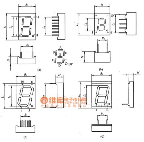
The FR series of LED digital display shape circuit diagram is shown as the chart. (View)
View full Circuit Diagram | Comments | Reading(924)
The structure indicating circuit diagram of glow numerating tube
Published:2011/4/27 22:24:00 Author:Ecco | Keyword: structure indicating , glow numerating tube
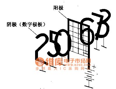
The glow numerating tube
The glow numerating tube is made by the glow discharging principle, the glass tube filled with neon gas is equipped with 10 cathodes with the word of 0,1,2 ... ... 9 and a common anode. The circuit is shown as the chart. The surface area of the cathode is almost the same with each other, but the distance between each anode and the anode is determined based on number of strokes. So under the same anode voltage, the necessary word will be lit by controlling each cathode voltage.
(View)
View full Circuit Diagram | Comments | Reading(599)
Multipurpose charging cirucit
Published:2011/4/13 4:10:00 Author:Nicole | Keyword: multipurpose charging
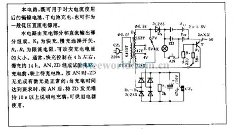
This circuit not only can charge to Ni-Cd battery and dry battery after used by large current, but also can used in general low voltage DC power supply.
The circuit consists of charging part and DC output part. K2 is fast or slow charging selection switch, R2, R3 is limiting resistance, it can change the charging current. Normally, the fast charging is about 4h and slow charging is about 14h. AN, ZD form testing circuit. Before charging,it shouldfix the stay rechargeable battery. When pressed AN, ZD is without light or has low light level, it is normal; When the charging time meets requirement, and press AN, after ZD emitting more than 10s, it means full, it can be used by the electrical equipments. (View)
View full Circuit Diagram | Comments | Reading(629)
TC9305-035 logic control system IC circuit
Published:2011/4/26 21:47:00 Author:TaoXi | Keyword: logic control system
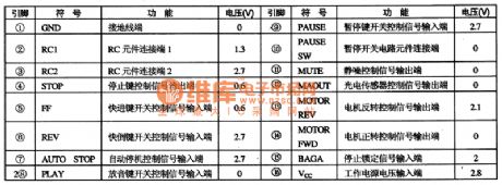
The TC9305-035 is designed as one kind of logic control system IC which is produced by the TOSHIBA company, this device can be used in wide range of applications such as the low voltage walkman, repeater. This device transforms the mechanical switch control signal to the microcomputer circuit.
1. Features
The TC9305-035 integrated circuit is composed of the switch control signal decoding circuit, the squelch control circuit, the motor reverse control circuit.etc.
2. Pin functions and data
TC9305-035 integrated circuit is in the 16-pin dual in-style package, the pin functions and data is as shown in table 1.
Table 1. The pin functions and data of the TC9305-035 (View)
View full Circuit Diagram | Comments | Reading(800)
135 film positioner (C180、TWH8751) circuit
Published:2011/4/26 21:44:00 Author:TaoXi | Keyword: film positioner
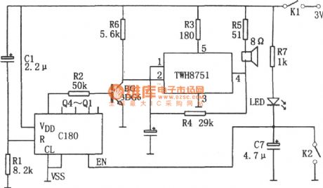
The 135 film positioner (C180、TWH8751) circuit is as shown. This circuit is composed of the counter C180 and TWH8751. And the TWH8751 forms the oscillator with 1kHz oscillation frequency.
The count switch K2 composed of the a wire and the device body at the position of 135 film's holes, when the 135 film moves, each time the contact plate contacts the body, this circuit produces a count signal. When you open this device, the contact plate of first hole contacts the body, C180 has been reset. When the nineth hole of the photo comes, there will be 8 count signal, so the Q4 of C180 has high-level voltage to turn on the BG, pin-4 outputs the signal to drive the speaker to tell master the photo is in position.
When the circuit is debugging, you should close the switch K2 first, then close the power switch K1 to make the LED light, Q1~Q4 have low-level voltage. Then turn on and off the K2 eight times, Q4 has high-level voltage. (View)
View full Circuit Diagram | Comments | Reading(1134)
The pin functions and data circuit of the TDA8178F
Published:2011/4/27 9:40:00 Author:TaoXi | Keyword: pin functions, data

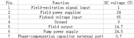
2. Pin functions and data
The pin functions and data circuit of the TDA8178F is as shown in table 50. And this device is in the 7-pin single in-line package.
Table 50 The pin functions and data circuit of the TDA8178F
(View)
View full Circuit Diagram | Comments | Reading(449)
Circuit of Free Debug FM Transceiver composed of BA1404 and TDA7021
Published:2011/4/26 9:01:00 Author:TaoXi | Keyword: Free Debug, FM Transceiver
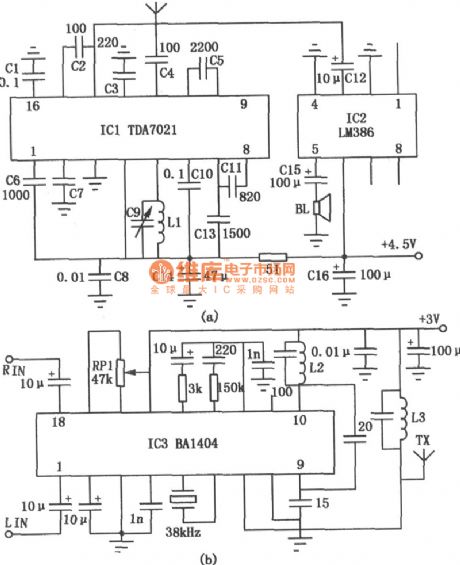
The most important features of this device are easy to make, it does not need to debug, especially this device does notneed the double-variable capacitor and intermediate frequency transformers, so it is very suitable tomake by the radio amateurs. Figure (a) is the receiving circuit; Figure (b) is the transmitter circuit.
When this circuit is transmitting the frequency of the signal 88 to 108MHz, the L2 use Φ0.65mm diameter enameled wire wound into 8mm, 10 turns of hollow coil. And the L3 use Φ0.6mm diameter enameled wire wound into 6mm, 8 turns of hollow coil.
(View)
View full Circuit Diagram | Comments | Reading(5345)
Motor protector 11
Published:2011/4/27 21:18:00 Author:Ecco | Keyword: Motor protector
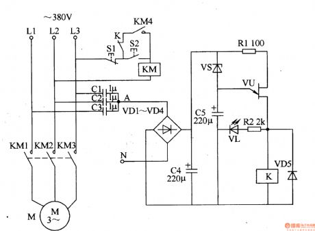
The motor protector described in the example has the protection function of phase auto delay and the features of simple circuit, without an external power supply, and it is suitable for all kinds of automatic (or manual) three-phase AC motor control equipment.
The working principle
The motor circuit protector circuit consists of capacitors CI-C5, diodes VDl-VD5, resistors Rl, R2, zener diode VS, light-emitting diode VL, VU prison junction transistors and relay K, it is shown as Figure 8-47.
When the three-phase power ofLl-L3 being normal, the AC voltage on junction point A of capacitors Cl-C3 will be lower, the voltage is rectified by the VDl-VD4, after being filtered by C4, it is insufficient to turn on VS and VU, K does not pull, the motor M operates normally.
When the three-phase power in the absence of a phase voltage, the place between the zero line and A point will quickly produce l2V AC voltage. This voltage is rectified by VDl-VD4 and filtered by C4, so that making VS breakdown conduction, C5 starts charging, after delaying several seconds (after C5 charging), VU turns, VL is lit, K pulls in, the contacts are off, so that the AC contactor KM releases, cutting off the working power source of motor M.
When the three-phase power is restored to normal, after a short delay, VU is off, K releases, then you can press the start button S2 to restart the motor. (View)
View full Circuit Diagram | Comments | Reading(1340)
Fushibao induction cooker circuit
Published:2011/4/27 21:45:00 Author:Christina | Keyword: Fushibao, induction cooker circuit
The Fushibao induction cooker circuit is as shown in the figure. (View)
View full Circuit Diagram | Comments | Reading(6508)
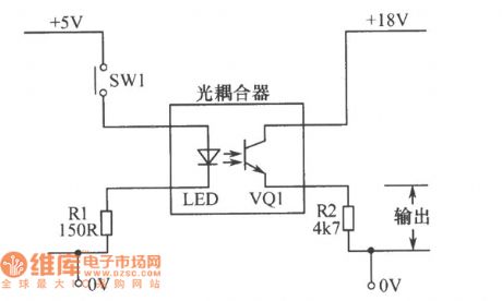
The basic optocoupler circuit diagram
Published:2011/4/27 21:54:00 Author:Ecco | Keyword: basic, optocoupler
View full Circuit Diagram | Comments | Reading(2046)
The glow numerating tube driver circuit diagram
Published:2011/4/27 22:01:00 Author:Ecco | Keyword: glow numerating tube , driver circuit
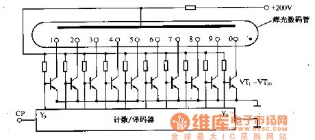
The glow numerating tube can be driven by a strong electric field, so it needs to be equipped with an electronic switch between decoder and the glow digital tube. The circuit is shown as the circuit, the VT1-VT10 is switch circuit composed of the semiconductor transistor.
(View)
View full Circuit Diagram | Comments | Reading(488)
| Pages:1992/2234 At 2019811982198319841985198619871988198919901991199219931994199519961997199819992000Under 20 |
Circuit Categories
power supply circuit
Amplifier Circuit
Basic Circuit
LED and Light Circuit
Sensor Circuit
Signal Processing
Electrical Equipment Circuit
Control Circuit
Remote Control Circuit
A/D-D/A Converter Circuit
Audio Circuit
Measuring and Test Circuit
Communication Circuit
Computer-Related Circuit
555 Circuit
Automotive Circuit
Repairing Circuit