
Circuit Diagram
Index 1997
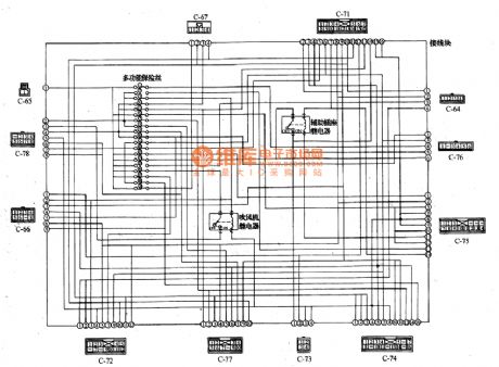
Mitsubishi Pagerlo light off-road vehicle circuit multifunction fuse terminal box internal wiring circuit diagram
Published:2011/4/27 2:55:00 Author:Nicole | Keyword: Mitsubishi Pagerlo, light off-road vehicle, multifunction fuse, terminal box
View full Circuit Diagram | Comments | Reading(694)
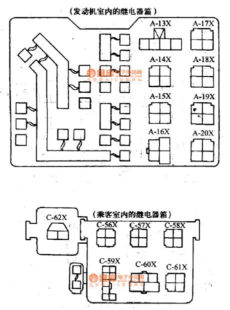
Mitsubishi Pagerlo light off-road vehicle circuit relay position circuit diagram
Published:2011/4/27 2:58:00 Author:Nicole | Keyword: Mitsubishi Pagerlo, light off-road vehicle, relay
View full Circuit Diagram | Comments | Reading(484)
Network voltage fault protection indication circuit
Published:2011/4/22 19:15:00 Author:Nicole | Keyword: network voltage, fault protection
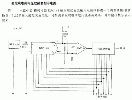
The circuit is as shown, the ouput termlnal of digital-analog converter DAC-08 connects to DC input voltage, then itwill form a typical digital-analog converter, the input is AC voltage, it can detect and find the network voltage sloughy or descendent, then it will use a output number to show it. (View)
View full Circuit Diagram | Comments | Reading(451)
Timer circuit with 106 fixed preset time
Published:2011/4/22 19:15:00 Author:Nicole | Keyword: timer, fixed preset time

The foot 13 between valve value 1 and valve value 2 will suck the transistor base current. If relay releases, after recovery time 0.5s, to press key then it will start to switch process again.
The timer is composed ofwindow discriminator TCA965 to. After pressing the key Ta , decision time capacitance C will charge. transistor T1 obtains base current from 2 foot of TCA965, power supply provides current. The process is timed ahead of 10s. During this time, the indicator light LD57 on. When the capacitance charge voltagesurpasses valve value 1 , the relay pulls-in. Once it reaches valve value 2 which is set by potentiometer Rp, the relay will release again. The relay pull-in time is in the range of 0~18s, it is adjustable. (View)
View full Circuit Diagram | Comments | Reading(1454)
Mitsubishi Pagerlo light off-road vehicle ceiling motor connection circuit diagram
Published:2011/4/27 2:39:00 Author:Nicole | Keyword: mitsubishi Pagerlo, light off-road vehicle, ceiling motor
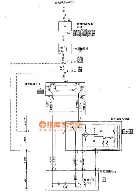
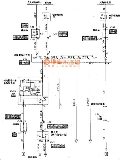
The colors of wiring: B: black LG: pale green G: green L: blue W: white Y: yellow SB: skyblue BR:brown O: orange GR: gray R: red P: pink V: violet (View)
View full Circuit Diagram | Comments | Reading(586)
Mitsubishi Pagerlo light off-road vehicle directional signal light and hazard warning light connection circuit diagram
Published:2011/4/27 2:44:00 Author:Nicole | Keyword: Mitsubishi Pagerlo, light off-road vehicle, directional signal light, hazard warning light
View full Circuit Diagram | Comments | Reading(1163)
The Driver Circuit of Soft Turn-off Adding Technology
Published:2011/4/21 21:45:00 Author:muriel | Keyword: soft turn-off technological
View full Circuit Diagram | Comments | Reading(818)
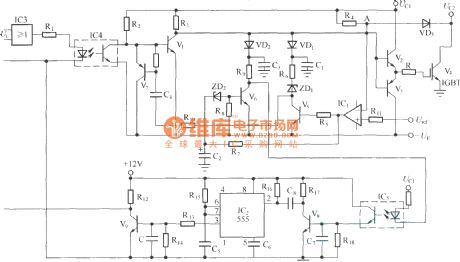
Comprehensive Short-circuit Protection Circuit of Decreasing Grid Voltage, Soft Shutoff, and Lowering Operating Frequency
Published:2011/4/21 21:43:00 Author:muriel | Keyword: Comprehensive Short-circuit Protection, Decreasing Grid Voltage, Soft Shutoff, Lowering Operating Frequency
View full Circuit Diagram | Comments | Reading(490)
Flashlight circuit supplyed by battery
Published:2011/4/25 4:32:00 Author:Nicole | Keyword: flashlight, battery
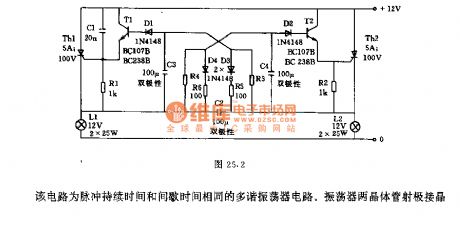
This is a multivibrator circuit with same pulse duration time and interval time. The two transistors emitter of oscillatorare connected to the gate of SCR, the two lights is flashing alternatively controlled by SCR. Capacitance C2, C3, C4 should use bipolar electrolytic capacitor. The voltage on capacitance C2 is 12V, the polarity alternatively changes with flashing rhythm. The voltage on C3, C4 changes between -12V ~Uz, Uz is SCR trigger voltage, the total of transistor T2 or T3's base-emitter cut-off voltage and diode D2 or D1's forward voltage drop is about 3V. Changing the resistance R3, R4 can change the flashing frequency, in figure, the oscillation frequency is 80/min. (View)
View full Circuit Diagram | Comments | Reading(783)
Floodlight power failure self-lock switch circuit
Published:2011/4/22 19:21:00 Author:Nicole | Keyword: floodlight, power failure, self-lock switch
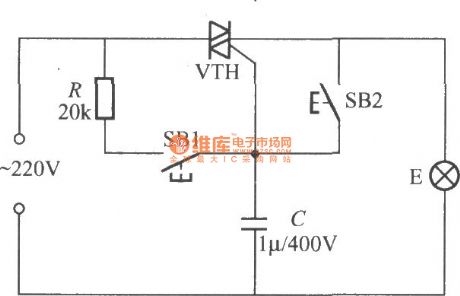
The floodlight is controlled by a ordinary stayguy switch, if it is power failure, it will be hard to differentiate whether the light is off, after it has power, the light will turn on all night, it is a waste of energy. If using this circuit to replace the ordinary stayguy switch, it will avoid this shortage, because it can beself-locked, the light will not be turned on. VTH should depend on the floodlight power, generally, it can use BCR3AM small plastic package TRIAC(3A/600V). (View)
View full Circuit Diagram | Comments | Reading(619)
60v/40mA regulated power supply circuit
Published:2011/4/20 1:18:00 Author:muriel | Keyword: 60v, 40mA , regulated power supply
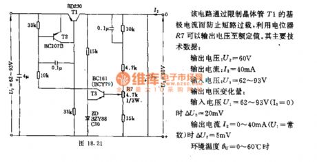
This circuit can prevent short circuit overload by limiting the base current of transistor T1 and output voltage to rated valut via potentiometer R7.
The main technical data:
output voltage:U2=60V
output current:I2=40mA
input voltage:U1=62V~93V
output voltage variable quantity:when output voltage U1=62V~93V(Io=0), ΔU2=20mV; when output current I2=0mA~40mA(U1=constant), ΔU2=5mV; ambient temperature θu=0°C~60°C.
(View)
View full Circuit Diagram | Comments | Reading(1376)
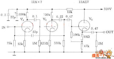
McIntosh C22 electron tube preamp circuit diagram
Published:2011/4/20 9:09:00 Author:Nicole | Keyword: McIntosh, electron tube, C22
View full Circuit Diagram | Comments | Reading(5616)
Battery charge protection circuit composed of PTC component and overvoltage protection component
Published:2011/4/27 1:33:00 Author:Nicole | Keyword: Battery charge, PTC component, overvoltage protection component
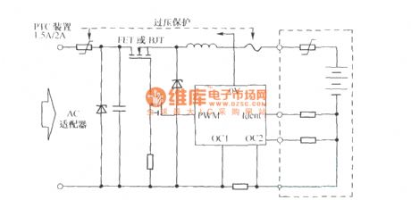
PTC component and overvoltage protection component work together to complete the following jobs: 1, Aiming at the large current which perhaps damage FET and batteries, it protects the current. 2, When it is reversed polarity, PTC action is used to limit the overcurrent produced by the zener diode positive conduction. 3, When the overvoltage component is protecting the voltage overload, the conduction current is limited by component. (View)
View full Circuit Diagram | Comments | Reading(1587)
Peak value hold circuit diagram composed of μPC151A
Published:2011/4/27 2:13:00 Author:Nicole | Keyword: peak value
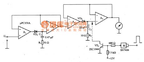
The figure of a peak value hold circuit composed of μPC151A is as shown. It is a peak value hold circuit and used to measure pulse. The first level peak value hold circuit is composed of A1 and A2, the capacity of charge capacitance should be as small as possible, then the peak value of inout singal will fast charge to it. The second level peak value hold circuit is composed of A3 and A4, charge capacitance C2 should use larger capacitance, then it can obtain the needed longer hold time. C2 should choose button capacitance.
(View)
View full Circuit Diagram | Comments | Reading(1834)
Ultrasonic remote control delay light receiver
Published:2011/4/25 4:34:00 Author:Nicole | Keyword: ultrasonic, remote control, delay light receiver
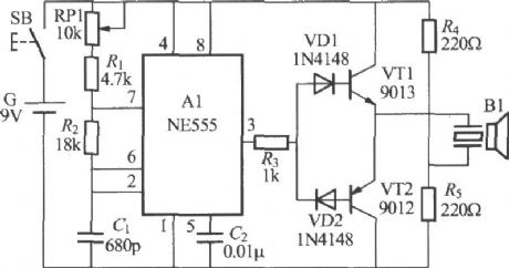
The figure is as shown, it is a delay light circuit uses ultrasonic as remote control command, when you use it, just to press the ultrasonic remote control transmitter(as below), the light will light up. Delaying about 1 min, the light will off automatically, it is very suitable for the use of getting up temporarily at night.
B1、B2 adopt well-assorted UCM-T40 and UCM-R40 piezoelectric ceramics ultrasonic transmit-receive converter.
(View)
View full Circuit Diagram | Comments | Reading(1062)
SH-818 high quality dual - tone seven functions color lamp control circuit
Published:2011/4/26 4:16:00 Author:Nicole | Keyword: color lamp
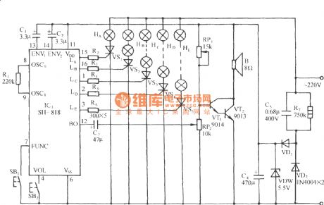
The circuit is as shown. SH-818 is made as the coretoformthis circuit. SH-818 is a high quality disyllable seven functions color lamp control circuit, it has many kinds of flashing patterns change programs, and with multiple double piano musics, the color lamp patterns will be changed with the music rhythm, then it will produce wonderful visual and audio effects. (View)
View full Circuit Diagram | Comments | Reading(552)
Refrigerator working indicator light circuit
Published:2011/4/26 4:22:00 Author:Nicole | Keyword: refrigerator, indicator light
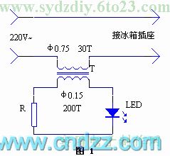
Adding a working indicator light to refrigerator power supply scoket is not only convenient to observe the refrigerator's start and stop, but also can increase the aesthetic feeling of socket.
The circuit is as shown in figure 1. LED is lighted up by the secondary induced current of current transformer. The current transformer can use a larger transistor radio input or output transformer, to reform it accordng to the graphic data. Pay attention to the interwinding is insulated.
(View)
View full Circuit Diagram | Comments | Reading(900)
Light emission and audio probe circuit
Published:2011/4/14 4:36:00 Author:Nicole | Keyword: light emission, audio probe
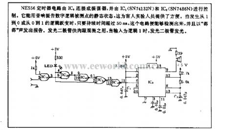
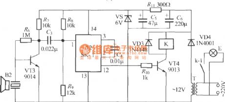
NE556 timer circuit is connected into oscillator by IC3, and controlled by IC1(SN74132N) and IC2(SN7486N). It can use audio vibration with digital logic point static state, it is convenient for blind experimental personnel. When it happens a logic abrupt change form 1 to 0 or 0 to 1, once the duration is beyond 50ns, this circuit can detect, and send out a report with dodo . LED is usedfor naked-eye observatio, when the input is logic 1, then LED light emits. (View)
View full Circuit Diagram | Comments | Reading(997)
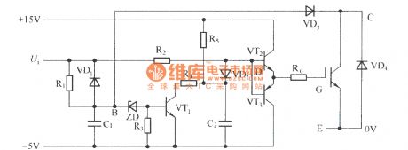
Changing the output voltage of ringing switching power supply circuit diagram
Published:2011/4/22 18:45:00 Author:Nicole | Keyword: switching power supply
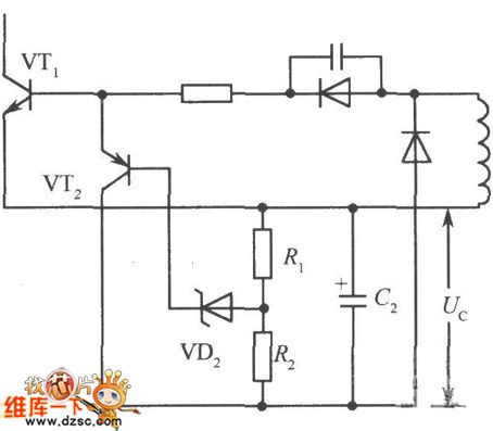
In the ringing choke type switching regulator circuit, the output voltage Uo is in direct proportion to the negative bias Uc, in order to change the output voltage, we should find a way to change Uc, as shown below.
The collector of transistor VT2 is connected on the negative terminal of capacitor C2. Once Uc2 increased, the base current of Zener diode VD2, transistor VT2 also increase, so that VT2 conducting. Because of the collector current VT2 can shorten the conduction time of switching transistor VTl than before, so it can be ended early, then to bring down the output voltage Uo.
(View)
View full Circuit Diagram | Comments | Reading(980)
Circuit diagram of buck-mode converted into boost-mode by CW34603
Published:2011/4/25 4:29:00 Author:Nicole | Keyword: buck-mode, boost-mode
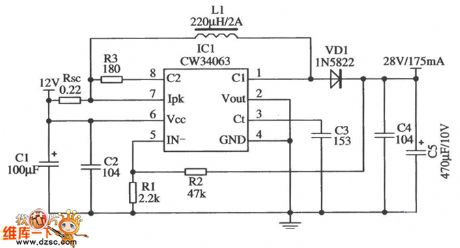
The figure is a typical application circuit of boost-mode. The input voltage is 12 V, output voltage is 28 V/175 mA, it only hasnine external components, the efficiency can reach 90%.
(View)
View full Circuit Diagram | Comments | Reading(600)
| Pages:1997/2234 At 2019811982198319841985198619871988198919901991199219931994199519961997199819992000Under 20 |
Circuit Categories
power supply circuit
Amplifier Circuit
Basic Circuit
LED and Light Circuit
Sensor Circuit
Signal Processing
Electrical Equipment Circuit
Control Circuit
Remote Control Circuit
A/D-D/A Converter Circuit
Audio Circuit
Measuring and Test Circuit
Communication Circuit
Computer-Related Circuit
555 Circuit
Automotive Circuit
Repairing Circuit