
Circuit Diagram
Index 1999
Light pipe amplifier circuit
Published:2011/4/24 7:11:00 Author:Nicole | Keyword: light pipe, amplifier circuit
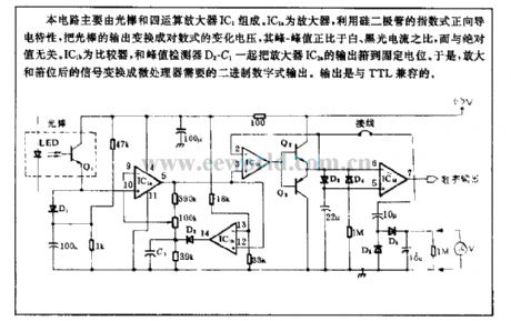
This circuit is composed of light pipe and four operational amplifiers IC1. IC1a is operational amplifier, using silicon diode's exponential positive conductivity to change the light pipe output to logarithmic voltage change, its peak-peak value is in direct proportion to the ratio of white and black light current, it is irrelevant to the absolute value. IC1b is comparator, the output of amplifier IC1a is rose to fixed level by IC1b and peak value detector. So the singal is transferred into the microprocessor needed binary digital output. The output is compatible with TTL. (View)
View full Circuit Diagram | Comments | Reading(850)
Tape recorders remote volume control circuit composed of LC2200
Published:2011/4/22 1:18:00 Author:Rebekka | Keyword: Tape recorders remote volume control
LC2190/2200 remote encoding transmitter / receiver is improved LC219/220A ASIC. It has the decoding and error identification repeated comparisons, so you can effectively prevent the error action.
LC2190 shape pin map.
LC2200 shape pin map.
LC219 internal block diagram.
LC2200A internal block diagram.
Main electrical parametersThe work oscillation frequency of LC2190 transmitter chip is 80kHz; Input duty cycle is 1:1, f = 40kHz square wave pulse; Repetition rate between output pulse train is decided by the the capacitors of CT end. It usually is 3 ~ 5Hz; Operating voltage range is 2.5 ~ 3.5V, typical value is +3 V; Quiescent power supply current is less than 1μA. The output can drive the power transistor to gain the large emission current. LC2200 receiver chip supply voltage range is 3 ~ 9v, typical value is +5 V; Quiescent supply current is less than 5μV; Each output drive current IoH ≥ 2mA, 10L ≥ 1mA. It can directly drive NPN transistor, LED and low power SCR.
Infrared transmitter circuit composed of LC2190.
Continuous key turns to a single-button circuit.
Remote control circuit included in the volume composed of LC2200.
(View)
View full Circuit Diagram | Comments | Reading(827)
High speed TTL probe circuit
Published:2011/4/17 8:00:00 Author:Nicole | Keyword: TTL probe
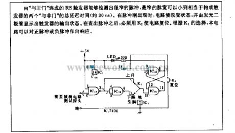
RS trigger is connected by NAND gate , it can test very narrow pulse, the narrowest pulse width is equal to the total delay time(about 30ns) of trigger's two NAND gate . When it appears pulse, the circuit will change the state, and it displays the output state of tigger by LED. After finding out the pulse, it must use K2 to reset the circuit. According to the choice of K1, this circuit will be in response to the positive pulse or negative pulse. (View)
View full Circuit Diagram | Comments | Reading(605)
Toyota Coaster bus automatic door circuit diagram
Published:2011/4/26 20:23:00 Author:Rebekka | Keyword: Toyota Coaster bus , automatic door
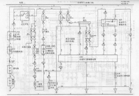
Toyota Coaster bus automatic door (folding doortype) circuit diagram (View)
View full Circuit Diagram | Comments | Reading(4922)
Toyota Coaster bus automatic door (slide door) circuit diagram
Published:2011/4/26 20:25:00 Author:Rebekka | Keyword: slide door, Toyota Coaster bus , automatic door
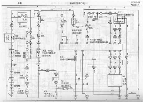
Toyota Coaster bus automatic door (slide door) circuit diagram is shown as above. (View)
View full Circuit Diagram | Comments | Reading(4748)
Toyota coaster bus start system and charging system circuit diagram
Published:2011/4/26 20:27:00 Author:Rebekka | Keyword: Toyota coaster bus , start system , charging system
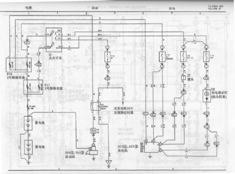
Toyota coaster bus start system and charging system circuit diagram is shown as above. (View)
View full Circuit Diagram | Comments | Reading(3672)
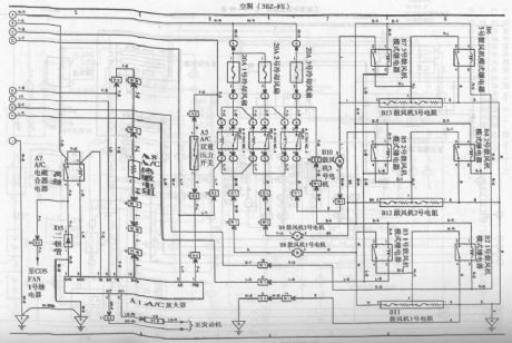
Toyota coaster bus air conditioning system circuit diagram 5
Published:2011/4/26 20:28:00 Author:Rebekka | Keyword: Toyota coaster bus , air conditioning system
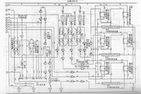
Toyota coaster bus air conditioning system circuit diagram is shown as above. (View)
View full Circuit Diagram | Comments | Reading(2794)
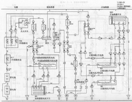
Toyota coaster bus air conditioning system circuit diagram 4
Published:2011/4/26 20:30:00 Author:Rebekka | Keyword: Toyota coaster bus, air conditioning system

Toyota coaster bus air conditioning system circuit diagram is shown as above. (View)
View full Circuit Diagram | Comments | Reading(4826)
Toyota Coaster bus engine circuit diagram 2
Published:2011/4/26 20:34:00 Author:Rebekka | Keyword: Toyota Coaster , bus engine
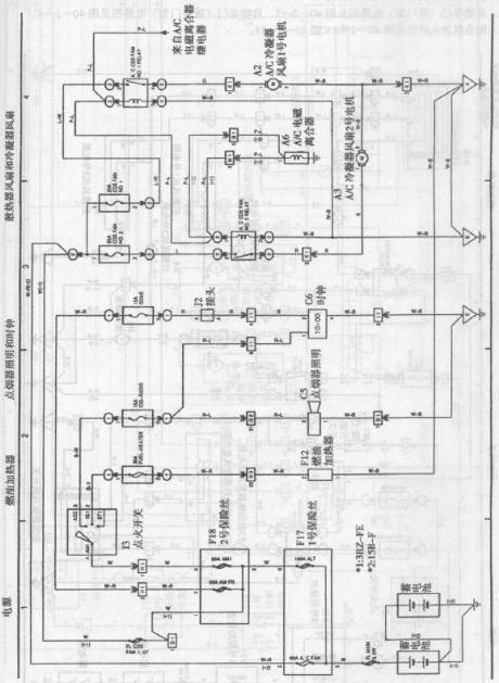
Toyota Coaster bus engine circuit diagram is shown as above. (View)
View full Circuit Diagram | Comments | Reading(939)
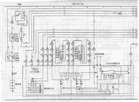
Toyota coaster bus air conditioning system circuit diagram 1
Published:2011/4/26 20:44:00 Author:Rebekka | Keyword: Toyota coaster bus, air conditioning system
Toyota coaster bus air conditioning system circuit diagram is shown as above. (View)
View full Circuit Diagram | Comments | Reading(4061)
Toyota coaster bus air conditioning system circuit diagram 2
Published:2011/4/26 20:31:00 Author:Rebekka | Keyword: Toyota coaster bus, air conditioning system
Toyota coaster bus air conditioning system circuit diagram is shown as above. (View)
View full Circuit Diagram | Comments | Reading(1759)
Toyota coaster bus air conditioning system circuit diagram 3
Published:2011/4/26 20:31:00 Author:Rebekka | Keyword: Toyota coaster bus , air conditioning system
Toyota coaster bus air conditioning system circuit diagram is shown as above. (View)
View full Circuit Diagram | Comments | Reading(1781)
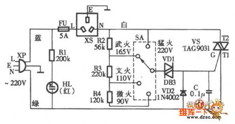
Xinmei VL-95Q electric rice and porridge cooker circuit diagram
Published:2011/4/26 10:23:00 Author:Nancy | Keyword: electric rice cooker, porridge cooker
View full Circuit Diagram | Comments | Reading(1757)
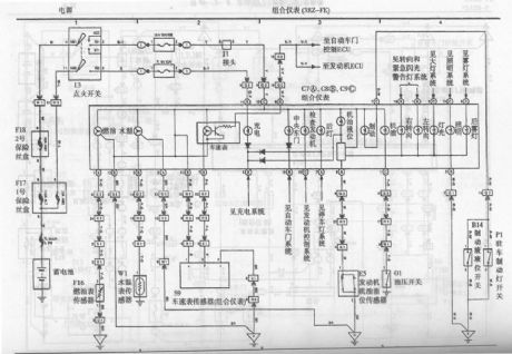
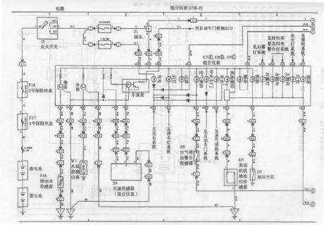
Toyota Coaster bus combination instrument circuit diagram 1
Published:2011/4/26 20:21:00 Author:Rebekka | Keyword: Toyota Coaster bus, combination instrument
View full Circuit Diagram | Comments | Reading(870)
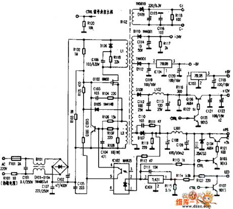
sv-250 power supply circuit diagram
Published:2011/4/26 10:23:00 Author:Nancy | Keyword: power supply
View full Circuit Diagram | Comments | Reading(686)
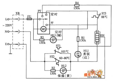
Timer automatic electric rice cooker circuit diagram
Published:2011/4/26 10:24:00 Author:Nancy | Keyword: Timer, automatic, electric rice cooker
View full Circuit Diagram | Comments | Reading(8130)
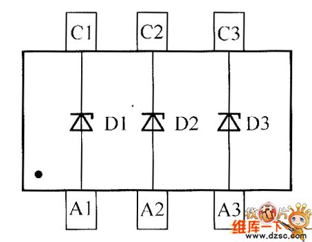
crystal diode DDZX5V6BTS internal circuit diagram
Published:2011/4/26 10:24:00 Author:Nancy | Keyword: crystal diode
View full Circuit Diagram | Comments | Reading(411)
Toyota Coaster bus combination instrument circuit diagram 2
Published:2011/4/26 20:20:00 Author:Rebekka | Keyword: Toyota Coaster bus, combination instrument
Toyota Coaster bus combination instrument circuit diagram is shown as above. (View)
View full Circuit Diagram | Comments | Reading(1134)
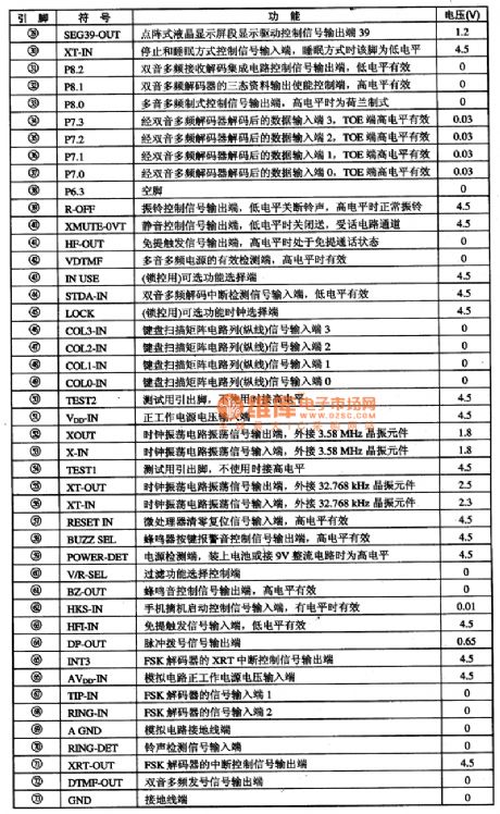
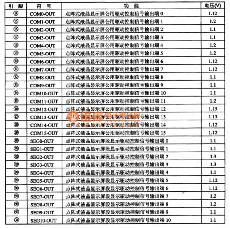
TCL868-CID03 Communication Single Chip Microcomputer Integrated Circuit
Published:2011/4/26 8:56:00 Author:TaoXi | Keyword: Communication Single Chip, Microcomputer Integrated
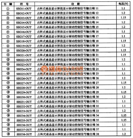
The TCL868CDO3 is the 4-bit CMOS microcomputer integrated circuit that belongs to the TCL company, this device can be used in TCL ID phone caller series.
1. Features
The TCL868CDO3 IC contains the BELL202 or ITU一TV23 standard FSK decoder, the dual audio signal generator, the four-detection platform for low-voltage detection circuit, the LCD driver circuit and the power-saving mode control circuit.etc. It can be used in the call data reception, process and display, and it also has the pulse / DTMF dialing compatible fuction.
2.Pin functions and data
The TCL868CDO3 IC is in the 100-pin softpackage, the IC's pin function and data is as shown in figure 1:
(View)
View full Circuit Diagram | Comments | Reading(632)
SN75365 Four TTL-MOS Driver Circuit
Published:2011/4/26 9:00:00 Author:TaoXi | Keyword: Four, TTL-MOS Driver
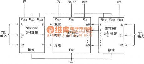
The SN75365 is one kind of TTL-MOS driver that has four NAND functions, this device is the connector between TTL circuits and high current or high voltage systems, so it drives the large capacitive loads andcan be usedwith a variety of common-MOS or RAM device. Also this device has the high-conversion speed, low power consumption, and each two drives have two public enable input pins, and the SN75365 has standard bipolar and MOS-circuit power supply. The wiring diagram of the SN75365 of type 4062 P-channel MOS RAMis as shown.
(View)
View full Circuit Diagram | Comments | Reading(1524)
| Pages:1999/2234 At 2019811982198319841985198619871988198919901991199219931994199519961997199819992000Under 20 |
Circuit Categories
power supply circuit
Amplifier Circuit
Basic Circuit
LED and Light Circuit
Sensor Circuit
Signal Processing
Electrical Equipment Circuit
Control Circuit
Remote Control Circuit
A/D-D/A Converter Circuit
Audio Circuit
Measuring and Test Circuit
Communication Circuit
Computer-Related Circuit
555 Circuit
Automotive Circuit
Repairing Circuit