
Circuit Diagram
Index 1988
Electron coupled oscillator circuit
Published:2011/4/11 2:39:00 Author:may | Keyword: Electron coupled oscillator
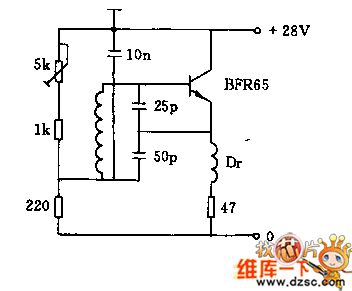
This circuit connected directly with collector, thus good for heat dissipation, under a given device parameters, the working frequency is 30MHz , the output coupling high frequency is about 0.8W. The following diagram is electron coupled oscillator circuit.
(View)
View full Circuit Diagram | Comments | Reading(895)
5MHz clock signal generater circuit
Published:2011/4/24 1:10:00 Author:May | Keyword: clock signal generater
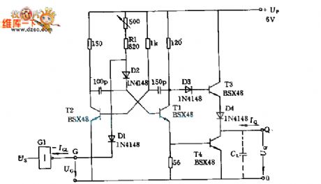
The transistor T1, T2 form a multiple harmonic oscillator, and connect to 500Ω adjustable resistance in series with fixed resistance R1 can adjust frequency. Transistor T3 and T4 compose output level, output current IQ is larger than 48mA when the low level UQL=0.4V, and 20mA when the high level UQH is 2.9V.
(View)
View full Circuit Diagram | Comments | Reading(587)
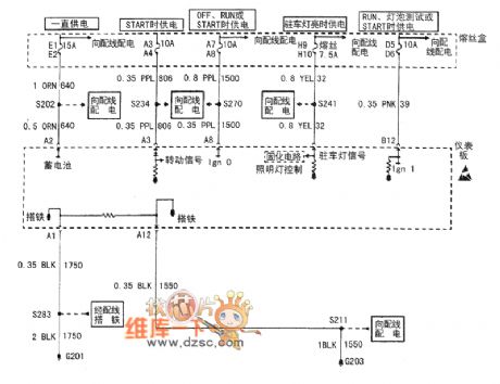
Buick Century car instrument board system circuit diagram(1)
Published:2011/4/28 1:48:00 Author:Nicole | Keyword: Buick Century, car, instrument board
View full Circuit Diagram | Comments | Reading(505)
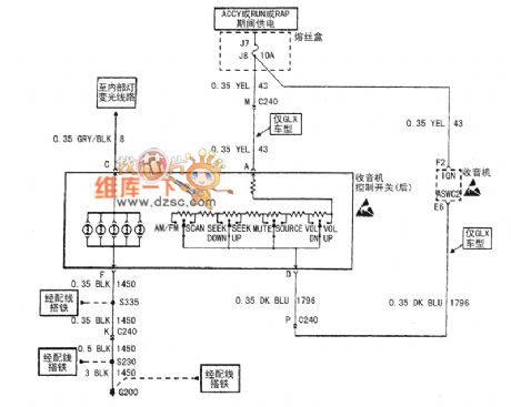
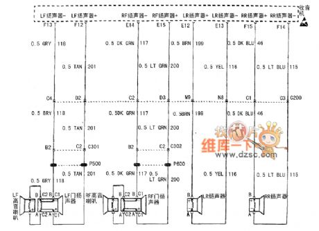
Buick Century car audio system circuit diagram(4)
Published:2011/4/28 1:57:00 Author:Nicole | Keyword: Buick Century, car, audio system
View full Circuit Diagram | Comments | Reading(518)
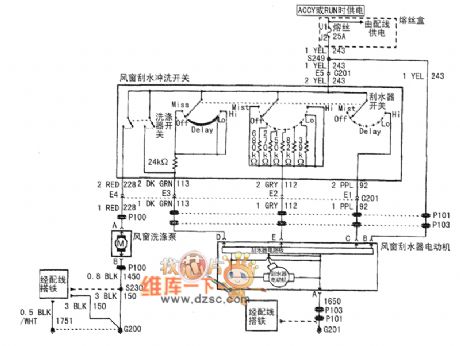
Buick Century car windscreen wiper-washer system circuit diagram
Published:2011/4/28 1:53:00 Author:Nicole | Keyword: Buick Century, car, wiper-washer system
View full Circuit Diagram | Comments | Reading(615)
IW transmitter circuit with frequency range of 16MHz
Published:2011/4/11 2:38:00 Author:may | Keyword: IW transmitter, 16MHz, frequency range
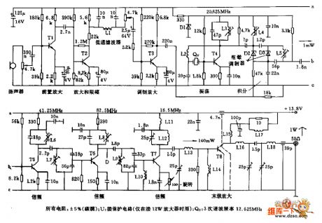
IW transmitter circuit of frequency 16MHz range is shown in the following diagram: (View)
View full Circuit Diagram | Comments | Reading(898)
Buick Century car audio system circuit diagram(2)
Published:2011/4/28 1:57:00 Author:Nicole | Keyword: Buick Century, car, audio
View full Circuit Diagram | Comments | Reading(488)
The wiring principle circuit diagram of PLC control pump motor
Published:2011/4/11 2:42:00 Author:may | Keyword: PLC control pump motor
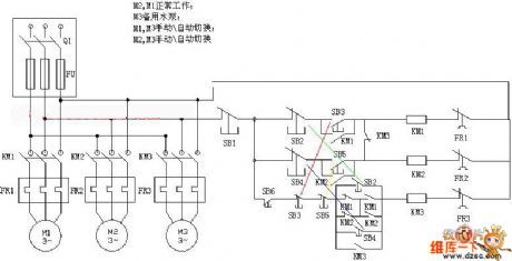
diagram: The wiring principle circuit diagram of PLC control pump motor (View)
View full Circuit Diagram | Comments | Reading(4396)
Baohua KC-14 window mode air conditioner circuit
Published:2011/4/24 1:11:00 Author:May | Keyword: window mode, air conditioner
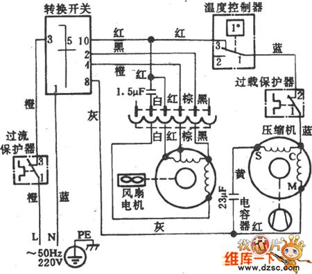
Baohua KC-14 window mode air conditioner circuit is show in the diagram:
(View)
View full Circuit Diagram | Comments | Reading(1706)
SN55476~SN55479 dual peripheral driver circuit
Published:2011/4/24 1:24:00 Author:May | Keyword: dual peripheral driver
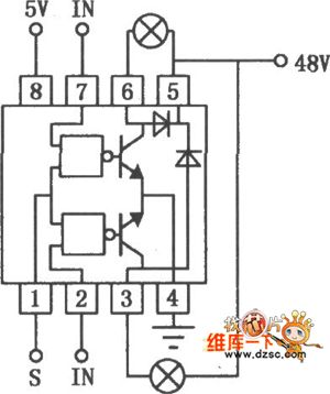
SN55476~SN75479 is high voltage, strong current and fast switch time double peripheral drive. Its output current is 300mA, output voltage is high, switch speed is fast, it has output clamp diode, input end with TTL and MOS circuit is consistent, it is very suitable for hammer driver. The connect lineof SN55477 using as lamp driver is shown in the diagram.
(View)
View full Circuit Diagram | Comments | Reading(903)
Huali KC-14、KC-16、KC-18、KC-23 window type air conditioner circuit
Published:2011/4/24 1:21:00 Author:May | Keyword: air conditioner, window type
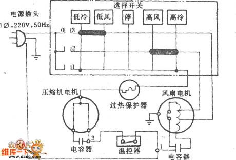
Huali KC-14、KC-16、KC-18、KC-23 window type air conditioner circuit is shown in the following diagram:
(View)
View full Circuit Diagram | Comments | Reading(2774)
Fan uses PTC devices to increase breeze gear circuit 2
Published:2011/4/11 2:48:00 Author:may | Keyword: Fan, PTC devices, breeze gear
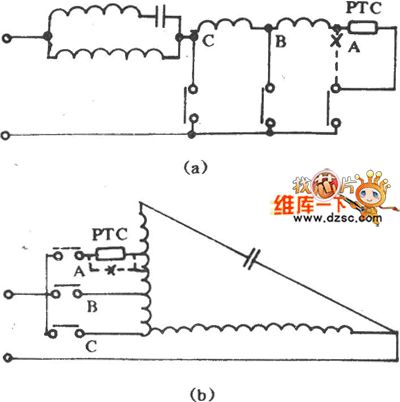
Fan uses PTC devices to increase breeze gear circuit is shown in the following diagram:
(View)
View full Circuit Diagram | Comments | Reading(764)
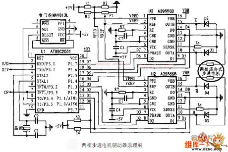
The principle circuit diagram of two diphase stepper motor driver
Published:2011/4/11 2:44:00 Author:may | Keyword: two diphase stepper motor, driver
View full Circuit Diagram | Comments | Reading(660)
The circuit diagram of electric fan adding breeze gear by capacitance
Published:2011/4/11 3:43:00 Author:may | Keyword: electric fan, adding breeze gear, capacitance
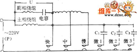
The circuit diagram of electric fan adding breeze gear by capacitance is shown in the following diagram:
(View)
View full Circuit Diagram | Comments | Reading(538)
Huali KCD-23 type window type air conditioner diagram
Published:2011/4/24 1:14:00 Author:May | Keyword: Huali, window type, air conditioner

Huali KCD-23 type window type air conditioner diagram is shown in the diagram:
(View)
View full Circuit Diagram | Comments | Reading(4559)
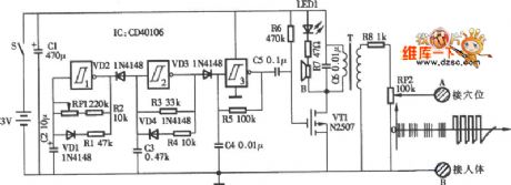
Electronic rabbit catcher schematic circuit diagram
Published:2011/4/14 5:47:00 Author:may | Keyword: Electronic rabbit catcher
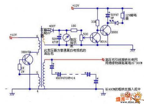
Electronic rabbit catcher schematic circuit diagram is shown in the following diagram:
(View)
View full Circuit Diagram | Comments | Reading(1026)
DC Motor armature core circuit diagram
Published:2011/4/11 2:55:00 Author:may | Keyword: DC Motor armature core
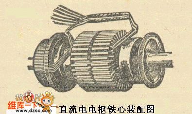
Two usage: [armature core assembly drawing ( diagram) ]
As major component of main magnetic circuit
Embedded armature winding is usually stamped and laminated by 0.5 mm silicon steel pates.
diagram: DC Motor armature core circuit diagram (View)
View full Circuit Diagram | Comments | Reading(1954)
DC motor static part circuit diagram
Published:2011/4/6 5:45:00 Author:may | Keyword: DC motor static part
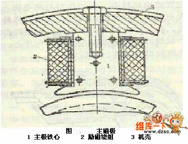
The main pole is an electromagnet, with an iron core laminated and tighten by 1-1.5mm steel blunt pieces.
diagram: DC motor static part circuit diagram (View)
View full Circuit Diagram | Comments | Reading(555)
Electrical pulse treatment circuit
Published:2011/4/2 4:26:00 Author:may | Keyword: Electrical pulse treatment
Electrical pulse treatment circuit is shown in the diagram:
(View)
View full Circuit Diagram | Comments | Reading(619)
Remote control type multi-range controller circuit
Published:2011/4/2 4:27:00 Author:may | Keyword: multi-range controller, Remote control
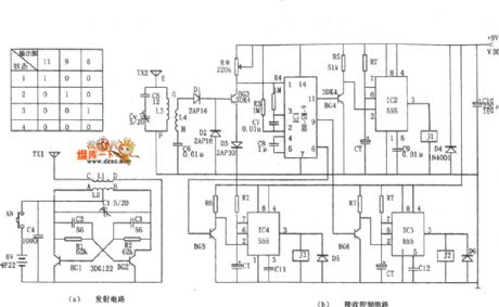
Remote control type multi-range controller circuit is shown in the diagram:
(View)
View full Circuit Diagram | Comments | Reading(562)
| Pages:1988/2234 At 2019811982198319841985198619871988198919901991199219931994199519961997199819992000Under 20 |
Circuit Categories
power supply circuit
Amplifier Circuit
Basic Circuit
LED and Light Circuit
Sensor Circuit
Signal Processing
Electrical Equipment Circuit
Control Circuit
Remote Control Circuit
A/D-D/A Converter Circuit
Audio Circuit
Measuring and Test Circuit
Communication Circuit
Computer-Related Circuit
555 Circuit
Automotive Circuit
Repairing Circuit