
Circuit Diagram
Index 1996
Using LM386 as mono-order generator circuit diagram
Published:2011/4/27 3:30:00 Author:Rebekka | Keyword: mono-order generator
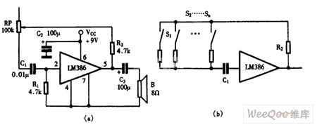
Using LM386 as mono-order generator circuit diagram is shown as above. (View)
View full Circuit Diagram | Comments | Reading(573)
Using KD-28 as single-chip radio circuit diagram
Published:2011/4/27 3:29:00 Author:Rebekka | Keyword: single-chip radio
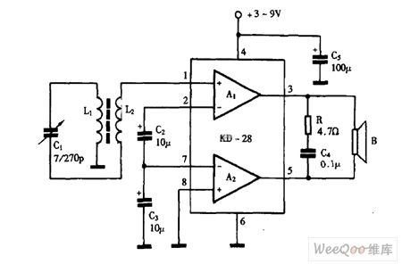
Using KD-28 as single-chip radio circuit diagram is shown as above. (View)
View full Circuit Diagram | Comments | Reading(1286)
Using LM386 as single-chip radio circuit diagram
Published:2011/4/27 3:28:00 Author:Rebekka | Keyword: single-chip radio
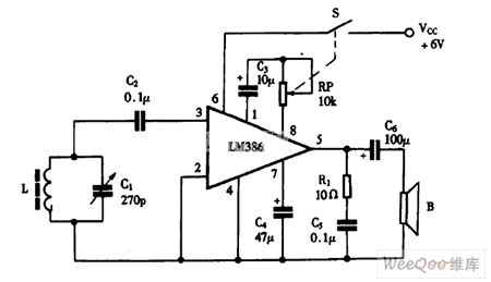
Using LM386 as single-chip radio circuit diagram is shown as above. (View)
View full Circuit Diagram | Comments | Reading(8019)
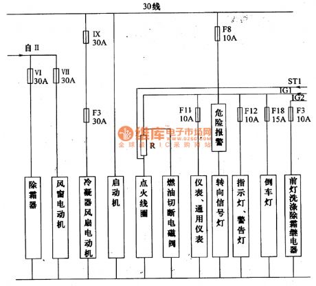
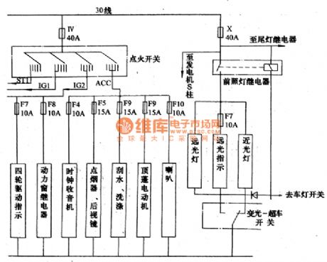
Mitsubishi Pagerlo light off-road vehicle outline circuit diagram(2)
Published:2011/4/27 3:17:00 Author:Nicole | Keyword: Mitsubishi Pagerlo, light off-road vehicle, outline
View full Circuit Diagram | Comments | Reading(503)
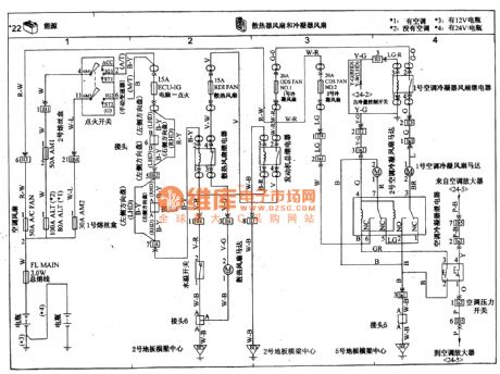
TOYOTA COASTER coach radiator fan and condenser fan circuit wiring circuit diagram
Published:2011/4/27 3:28:00 Author:Nicole | Keyword: TOYOTA COASTER, coach, radiator fan, condenser fan
View full Circuit Diagram | Comments | Reading(1933)
555 Optical toy car circuit
Published:2011/4/26 22:19:00 Author:Ecco | Keyword: 555, Optical , toy car
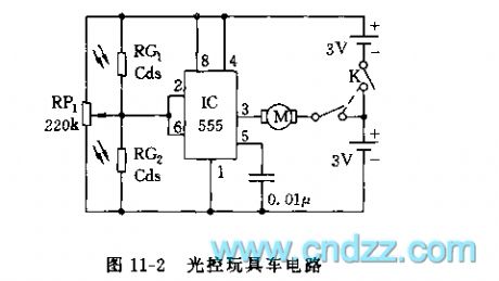
As shown in Figure 11-2, IC (555) is connected as dual stable trigger. RG1, RG2 are photoresistors, which are packed in the car's left window and right window (or front and back), when the RG1 is suffered illumination, its resistance declines sharply, pin 6 is in high level, 555 resets, pin 3 is in low level, the motor M reversing and turning right; or turning left. (View)
View full Circuit Diagram | Comments | Reading(1001)
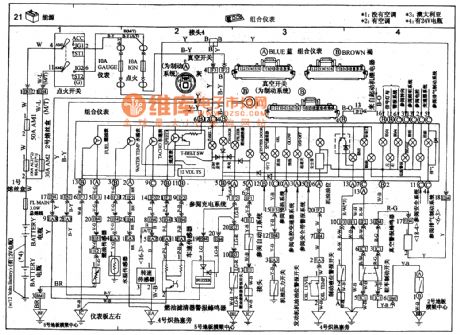
TOYOTA COASTER coach combined meter circuit wiring circuit diagram
Published:2011/4/27 3:25:00 Author:Nicole | Keyword: TOYOTA COASTER, coach, combined meter
View full Circuit Diagram | Comments | Reading(2753)
Mitsubishi Pagerlo light off-road vehicle outline circuit diagram(1)
Published:2011/4/27 3:18:00 Author:Nicole | Keyword: Mitsubishi Pagerlo, light off-road vehicle, outline
View full Circuit Diagram | Comments | Reading(492)
Toyota Coaster bus engine circuit diagram
Published:2011/4/27 2:15:00 Author:Rebekka | Keyword: Toyota Coaster , bus engine
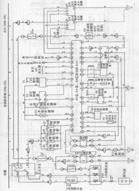
Toyota Coaster bus engine circuit diagram is shown as above. (View)
View full Circuit Diagram | Comments | Reading(3754)
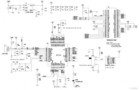
Using CXA1191 German Desheng radio circuit diagram
Published:2011/4/27 3:07:00 Author:Rebekka | Keyword: German Desheng, radio circuit
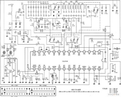
Using CXA1191 German Desheng radio circuit diagram is shown as above. (View)
View full Circuit Diagram | Comments | Reading(8290)
Mitsubishi Pagerlo light off-road vehicle outline circuit diagram(3)
Published:2011/4/27 3:13:00 Author:Nicole | Keyword: Mitsubishi Pagerlo, light off-road vehicle, outline
View full Circuit Diagram | Comments | Reading(478)
88MHz-108MHz 15W FM transmitter high-frequency amplifier circuit diagram
Published:2011/4/27 3:05:00 Author:Rebekka | Keyword: FM transmitter, high-frequency amplifier
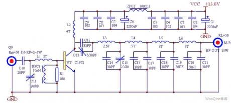
88MHz-108MHz 15W FM transmitter high-frequency amplifier circuit diagram is shown as above. (View)
View full Circuit Diagram | Comments | Reading(4875)
FM wireless headset circuit diagram
Published:2011/4/27 3:03:00 Author:Rebekka | Keyword: FM wireless headset
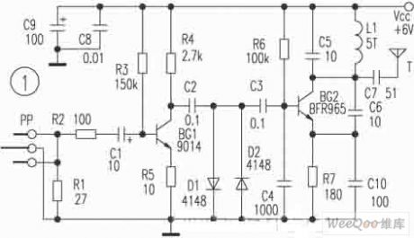
FM wireless headset circuit diagram is shown as above. (View)
View full Circuit Diagram | Comments | Reading(1239)
80mW FM transmitter circuit diagram
Published:2011/4/27 3:02:00 Author:Rebekka | Keyword: FM transmitter
80mW FM transmitter circuit diagram is shown as above. (View)
View full Circuit Diagram | Comments | Reading(2361)
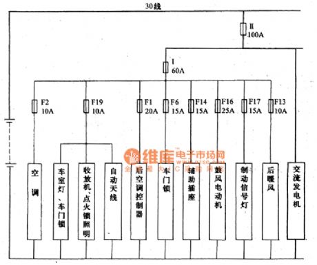
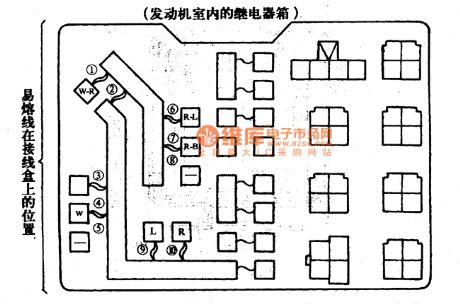
Mitsubishi Pagerlo light off-road vehicle circuit fusible link position circuit diagram
Published:2011/4/27 3:09:00 Author:Nicole | Keyword: Mitsubishi Pagerlo, light off-road vehicle, fusible link
View full Circuit Diagram | Comments | Reading(458)
Single-tube radio transmitter circuit diagram
Published:2011/4/27 3:00:00 Author:Rebekka | Keyword: Single-tube radio, transmitter circuit
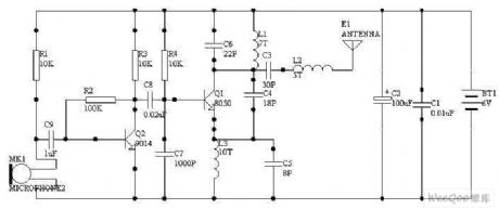
Single-tube radio transmitter circuit diagram is shown as above.
Note: The launch transistor uses the 9018.
(View)
View full Circuit Diagram | Comments | Reading(2792)
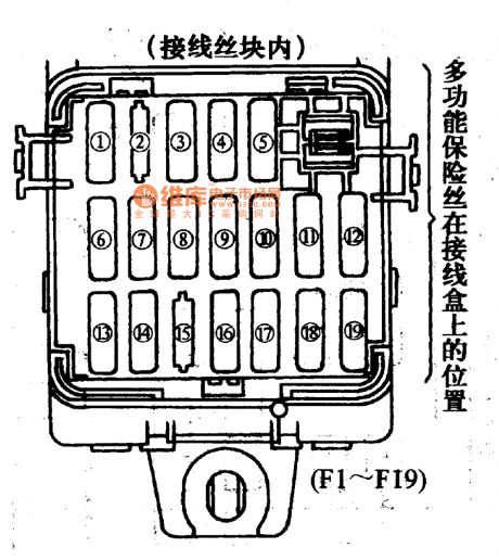
Mitsubishi Pagerlo light off-road vehicle circuit multifunction fuse position circuit diagram
Published:2011/4/27 3:01:00 Author:Nicole | Keyword: Mitsubishi Pagerlo, light off-road vehicle, multifunction fuse
View full Circuit Diagram | Comments | Reading(533)
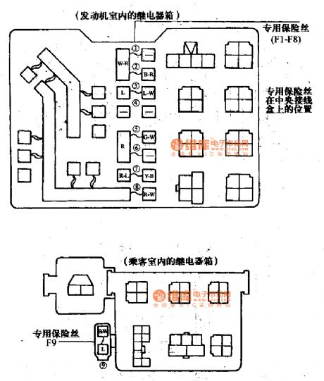
Mitsubishi Pagerlo light off-road vehicle circuit special fuse position circuit diagram
Published:2011/4/27 3:06:00 Author:Nicole | Keyword: Mitsubishi Pagerlo, light off-road vehicle, special fuse
View full Circuit Diagram | Comments | Reading(535)
555 Inductive switching power supply circuit
Published:2011/4/27 2:35:00 Author:Ecco | Keyword: 555 , Inductive , switching , power supply
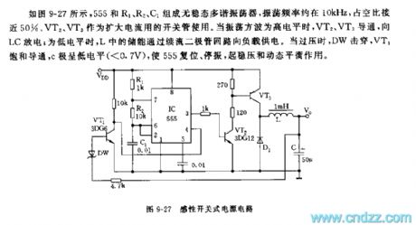
As shown in Figure 9-27, 555 and R1, R2, C1 form an astable multivibrator, the oscillation frequency is about 10kHz, duty cycle closes to 50%. VT2, VT3 are used as the switching tube to expand the current. When the shock wave is in high level, VT2, VT3 are conducted to discharge for LC ; when it is in low level, the energy storage in L provides power for load through the freewheeling diode loop. When overvoltage, DW is punctured, VT1 is saturated conducted, C is in low level, so that 555 resets and stops vibration, it plays the role of regulation and homeostasis.
(View)
View full Circuit Diagram | Comments | Reading(2499)
555 special power supply for razor
Published:2011/4/27 2:18:00 Author:Ecco | Keyword: 555 , special power supply , razor
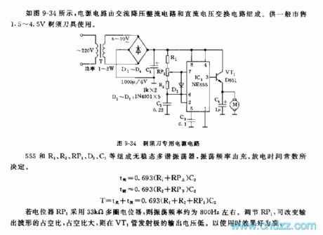
As shown in Figure 9-34, the power circuit is composed of AC step-down rectifier circuit and DC voltage conversion circuit. It is used for 1.5V ~ 4.5V razors sold in general market. 555 and R1, R2, RP1, D5, C2 etc. form an astable multivibrator, the oscillation frequency is decided by the charging and discharging time constant. If the potentiometer RP1 uses 33kΩ multi-turn potentiometer, the oscillation frequency is about 800HZ, adjusting RP1 can change the output waveform duty cycle, the duty cycle is large while the output voltage of the emitter of VT1 pipe is low. The using effect is the criterion.
(View)
View full Circuit Diagram | Comments | Reading(823)
| Pages:1996/2234 At 2019811982198319841985198619871988198919901991199219931994199519961997199819992000Under 20 |
Circuit Categories
power supply circuit
Amplifier Circuit
Basic Circuit
LED and Light Circuit
Sensor Circuit
Signal Processing
Electrical Equipment Circuit
Control Circuit
Remote Control Circuit
A/D-D/A Converter Circuit
Audio Circuit
Measuring and Test Circuit
Communication Circuit
Computer-Related Circuit
555 Circuit
Automotive Circuit
Repairing Circuit