
Circuit Diagram
Index 1991
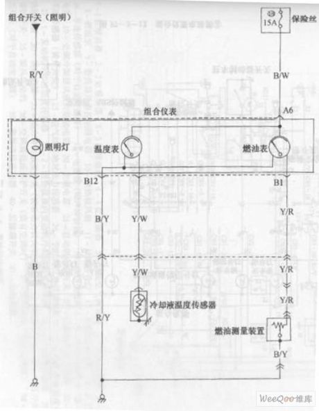
Changan Star multi-purpose vehicle combination instrument circuit diagram 2
Published:2011/4/28 1:04:00 Author:Rebekka | Keyword: Changan Star , multi-purpose vehicle , combination instrument
Changan Star multi-purpose vehicle combination instrument circuit diagram is shown as above. (View)
View full Circuit Diagram | Comments | Reading(663)
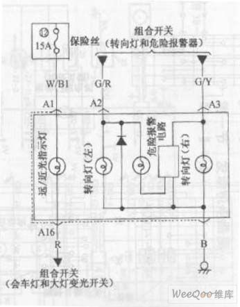
Changan Star multi-purpose vehicle combination instrument circuit diagram 1
Published:2011/4/28 1:04:00 Author:Rebekka | Keyword: Changan Star , multi-purpose vehicle , combination instrument
Changan Star multi-purpose vehicle combination instrument circuit diagram is shown as above. (View)
View full Circuit Diagram | Comments | Reading(668)
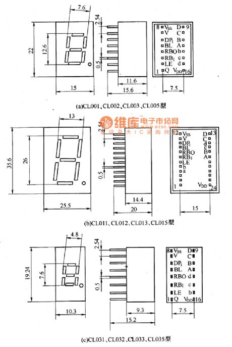
BCD code LED digital display components appearance circuit diagram
Published:2011/4/28 1:04:00 Author:Ecco | Keyword: BCD code, LED , digital, display components , appearance
View full Circuit Diagram | Comments | Reading(1157)
A Reliable Ultrasonic Remote Control Switch Circuit
Published:2011/4/27 18:37:00 Author:Christina | Keyword: Reliable, Ultrasonic Remote Control
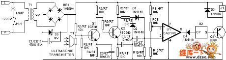
Transmitter circuit: u1 and external components form the multivibrator, after press the sw1, the output signal of u1(3) pin drive the ultrasonic transducer chip y1 by q1,q2 to sent out the ultrasonic signal.
Receiving circuit: in the standby mode, the electronic-level of u1(3) pin is higher than (2) pin, (6) pin sends out high electronic-level, trigger u2 holds the low output electronic-level, q3 cuts off, relay does not operate, so the lamp does not light; When the y1 received ultrasonic signal, after frequency selected amplification and rectification filtering, the signal get into the u1(2) pin, (6) pin becomes low electronic-level, trigger sends out high electronic-level, q3 connects and relay picks, the lamp is light as shown:
(View)
View full Circuit Diagram | Comments | Reading(1081)
PWM Control Dimming Halogen Lamp Circuit
Published:2011/4/27 18:39:00 Author:Christina | Keyword: PWM Control, Dimming Halogen Lamp
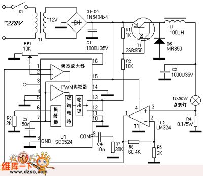
The PWM control dimming halogen lamp circuit is as shown. Rated voltage of the halogen lamp is 12V, the nominal power is 20W, the dimmer circuit can adjust the intensity of halogen lamp from zero to maximum.
Lighting halogen lamp always transforms the frequency electricity (220V or 110V) into 12V AC voltage by using the power transformer. In order to provide operating voltage to the pwm controller sg3524 (ic1) and the op amp lm324 (ic2), the DC voltage will apply to the ic1's 15-pin and 4-pin of ic2. Between the rectifier filter circuit and the halogen lamp, we need to connect the pnp compound transistor vt1 and the vt1 is controlled by the pwm signal of ic1. Through the collector output transistor of vt1, we connect the l1 and c2 to form the lc filter, so we can get the 12V DC voltage to supply power. As the lamp current is 1.67a (20 w/12 v), r4 is 0.1v, the output voltage (5V) sent by ic2's 1-pin will be back to the ic1's 1-pin.
(View)
View full Circuit Diagram | Comments | Reading(5019)
Multipurpose Exposure Timer Circuit
Published:2011/4/27 18:40:00 Author:Christina | Keyword: Multi-exposure, Exposure Timer
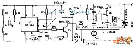
The device can satisfy the photographers to master the appropriate exposure to ensure the quality of photos. This device has many features such as accurate timing, wide-ranging application, exposure timing, dimming.etc. Bulb of enlarger or Electric irons, electric blankets, lamps, electric fans and motors can be connected to the output sockets CZ, the output power limited by the capacity of SCR, if it is a pure resistive load, this device can provide 600W of output power; if it is capacitive or inductive load, the output power is less than 300W.
(View)
View full Circuit Diagram | Comments | Reading(620)
Simple Automatic Emergency Light Circuit
Published:2011/4/27 18:40:00 Author:Christina | Keyword: Simple, Automatic Emergency Light
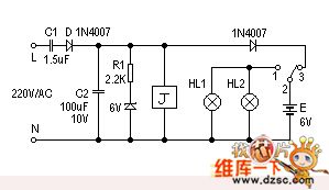
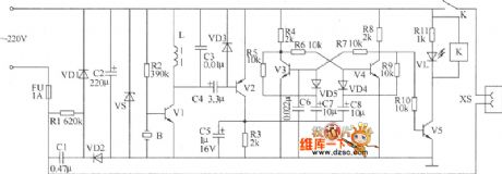
Here is a very simple but very useful emergency light. This device will turn on the small light automatically if the we meet power failure or fuse-cutoff. The circuit uses fewer components, andthis deviceis cheap and simple to make, so it is very suitable for home use.
The circuit is as shown. When the grid is normal, 220V mains voltage is reduced by the capacitor c1, and is half-wave rectified by the diode d, the circuit has the stable DC output voltage (6v) and 90ma output current. The power supplier still supplies power to relay j, the normally close contact point j2-1 disconnects, so hl1, hl2 lost power;on the other hand, the normally open contact point j2-3 disconnects, pulse current float to the battery E.
(View)
View full Circuit Diagram | Comments | Reading(1713)
Weak Light Measurement Circuit
Published:2011/4/27 18:41:00 Author:Christina | Keyword: Weak Light, Measurement
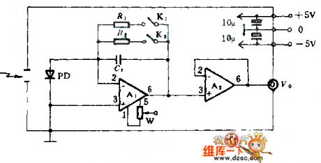
The PD in this figure is one kind of photodiode such as S1226,S1336,S2386.etc (produced by the Hamamatsu Corporation), A1 is the operational amplifier, model can be the AD515,OPA111,OPA128.etc; A2 is the operational amplifier OP-07; capacitor (C1) can use the 10 to 100pF burning polystyrene capacitor; feedback resistor R is the metal glaze resistor, the maximum is 10GΩ; K is the low-leakage relay. The whole circuit is in the metal shield box, the shield box and the circuit ground is connected. In the figure, W is the pioneer 0 circle precision potentiometer.
(View)
View full Circuit Diagram | Comments | Reading(722)
lm4766+ne5532 package 2x40w amplifier circuit
Published:2011/4/27 20:59:00 Author:Christina | Keyword: lm4766+ne5532 package, 2x40w amplifier
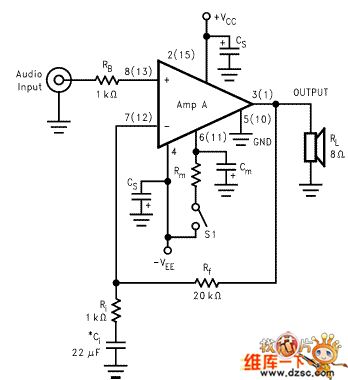
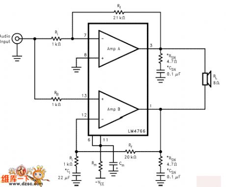
The following figure is the typical application circuit of this ic (btl mono)
In the first stage amplifier, by change the ratio of r3/r2, you can change the first stage magnification. User can reset the source of sound by the actual situation, usually between 1-10 times.
The power supply section uses the current and voltage integrated dynamic feedback circuit, this circuit has two advantages, for details, please see the related website of the tda7293/lm3886.
The power supply section uses the three-terminal voltage regulator power supplier, r18/re18 is the current limit resistor (10 to 30 ohm), c9/ce9 is the 6800/35v large reservoir capacitors, power supply decoupling small capacitor is 0. 1u is the cbb capacitor of wima.
The lm4766 has the warm tone, similar to the tube amp tone and the lm1875, but the power of lm4766 is larger than lm1875, I think it is the upgrade of lm1875, that's why it is the most popular ic of the music fans. Especially the friends who like the sound of lm1875. (View)
View full Circuit Diagram | Comments | Reading(7027)
Simple Timer Circuit Composed Of MC14541
Published:2011/4/27 6:42:00 Author:Robert | Keyword: Simple Timer
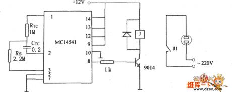
A Simple Timer Circuit conposed of MC14541 is shown below. This Circuit is a simple timing circuit using the IC MC14541. As the parameters shown in the picture, the circuit will time 3 hours, you could choose differential RTC,CRC or Rs value, to get the control of timing you need.
(View)
View full Circuit Diagram | Comments | Reading(4083)
Sub-Ultrasonic Remote Control Switch Circuit
Published:2011/4/27 6:42:00 Author:Robert | Keyword: Sub-Ultrasonic, Remote Control Switch
Sub-Ultrasonic Remote Control Switch Circuit is shown below:
(View)
View full Circuit Diagram | Comments | Reading(638)
Office Electric Heating Plate Automatic Switch Circuit
Published:2011/4/27 6:43:00 Author:Robert | Keyword: Office Electric Heating Plate, Automatic Switch
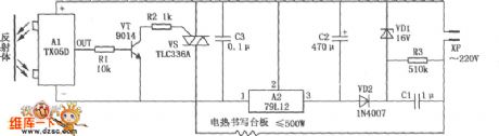
Office Electric Heating Plate Automatic Switch Circuit is shown as below. Based on the normal office desk electric plate heter, it equips the infrared reflection automatical switches composed of the TX50D module, can achieve the goal that automatical power up and heating whenpeople are workingon the plate, and automatic power down and stop heating when nobody there. This circuit could not only save the power, avoid the fash brought by the frequent plugs, but also can extend the life of the office electric heating plate and prevent the occurrence of accidents, it could be connected directly to the normal office electric heating plate, and is easy to produce, stable to work.
(View)
View full Circuit Diagram | Comments | Reading(899)
Wien bridge sine wave oscillator circuit composed of LM101A
Published:2011/4/20 6:19:00 Author:Ecco | Keyword: Wien bridge , sine wave , oscillator circuit

The chart shows the Wien bridge sine wave oscillator circuit. The amount of negative feedback circuit is determined by the internal resistance of FET. When the peak value of oscillator output reaches the regulated voltage of regulator diode D1, Q2 turns on, then the grid of Q1 FET becomes negative, Q1's drain - source resistance increases, the negative feedback increases, loop gain decreases. Similarly, when the oscillation amplitude decreases, the loop gain will increase, therefore, it can maintain a certain output range. C1, C2, R1 and R2 constitute a positive feedback loop to ensure the circuit oscillation. Connecting a l00kΩ resistor between drain and gate or gate and source of FET will ensure the FET working in the linear region and reducing distortion. Circuit oscillation frequency: f0 = 1/2π. According to the component value of the figure, the oscillation frequency R1C1 is calculated approximately 1.6kHz. (View)
View full Circuit Diagram | Comments | Reading(2370)
Double bits LED digital display appearance circuit diagram
Published:2011/4/28 0:47:00 Author:Ecco | Keyword: Double bits, LED, digital display, appearance

View full Circuit Diagram | Comments | Reading(559)
450/800Hz signal generator
Published:2011/4/20 7:01:00 Author:Ecco | Keyword: 450Hz , 800 Hz , signal generator
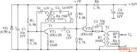
450/800Hz oscillator circuit shown as the chart is a transformer coupled oscillator. The changing of frequency is realized by changing the Tl tap of oscillation tank to achieve different inductance. Pulling the signal control switch S to the 1 block, the oscillation circuit C4 and l-2 end of Tl-side connects in parallel, the frequency is 800Hz, and it is output by VT2 emitter to the adjustable arm of RP potentiometer. Adjusting the potentiometer will change the size of 800Hz output. R4 in oscillation circuit is used to adjust the oscillation amplitude. Pulling the S to the 2 block, C and 1-3 phase of T1 connects, the oscillation frequency is 450Hz. Adjusting T1 threaded lever can fine-tune the oscillation frequency of the oscillator.
(View)
View full Circuit Diagram | Comments | Reading(574)
Quartz crystal sinusoidal oscillator
Published:2011/4/25 4:46:00 Author:Ecco | Keyword: Quartz crystal, sinusoidal oscillator
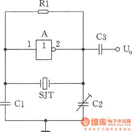
The circuit shown as the chart is a sine wave oscillator which is composed of the quartz crystal resonator SJT and one gate of six inverter IC CD4069. And comparing with ordinary RC phase shift oscillator, the crystal oscillator's frequency stability can be up to 0.00001 or higher. This is the high targets which RC phase-shift oscillator can not achieve (RC phase shift oscillator frequency stability can only reach the order of 0.01). CMOS NAND gate and negative feedback bias resistor Rl form the inverting amplifier. Quartz crystal SJT and Cl, C2 constitute a 7c positive feedback subcircuit. When quartz crystal is in the vicinity of its natural resonance frequency, it is self-inductive, the inductors and capacitors Cl, C2 constitute a resonant circuit, the forming selective frequency phase shift feedback network is back to the amplifier input to produce oscillation. Adjusting the capacitor C2 can fine-tune the oscillation frequency. Components Selection: Six inverter manifold A: CD4069. Capacitor Cl: 20pF, C2: 3 ~ 22pF, C3: 1000pF. Resistor Rl: 10MΩ. Crystal SJT: 32.768kHz. Circuit connection method: six integrated circuit CD4069 inverter only uses 1 / 6 door, the remaining doors can be used to connect to its input termination VDD or VSS when no other uses, the output is floating. (View)
View full Circuit Diagram | Comments | Reading(1332)
Stable sine wave oscillator composed of F007
Published:2011/4/21 6:39:00 Author:Ecco | Keyword: Stable sine wave oscillator
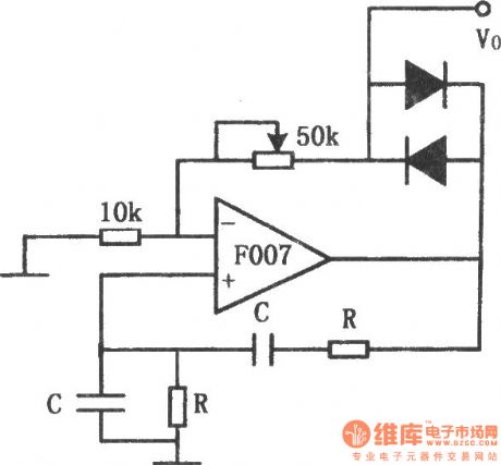
The chart shows the stable sine wave oscillator circuit. In order to obtain a stable oscillation, it requires a loop gain with 1. If the gain is too large, the waveform will occur distortion; if the gain is too small, the circuit will stop vibration. This circuit uses two diodes to stabilize the oscillation. When the output voltage is too low, the diode cuts off, negative feedback is cut off, the loop gain to improve the output voltage increased. When the output reaches a certain value, the diode conduction, the loop gain is improved, output voltage increases. And when the output rate reaches a certain value. The potentiometer in the figure is used to adjust the output amplitude and distortion. The oscillation frequency of the circuit is decided by the resistor R and capacitor C: f0 = 1/2πRC.
(View)
View full Circuit Diagram | Comments | Reading(861)
56 ~ 512kHz high frequency oscillator
Published:2011/4/20 22:05:00 Author:Ecco | Keyword: 56 ~ 512kHz , high frequency , oscillator
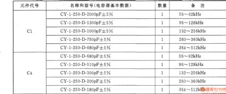
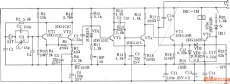
The chart shows the 56 ~ 512kHz high frequency oscillator. It consists of high-frequency oscillator, the alarm circuit. 1. Specifications: (1) Frequency range: 56 ~ 512 kHz; (2) Output Level: +5.5 ± ldB; (3) Frequency Accuracy: less than ± 20Hz; (4) warning signal: when stopping vibration, the warning light turns on and the circuit emits alarm sound. (5) Operating temperature: 0 ~ +45 ℃ assurance indicators, -10 ~ 0 ℃, +45 ~ +50 ℃; reliable working components’ choice: Transistor VTl ~ VT4: 3DGl01C, β = 65 ~ 85, VT5 ~ VT6: 3DGl308 , β = 85 ~ 115. Crystal SJT: the model is 101 quartz crystal, crystal with t feet that is GZC7-F. The choices of capacitors Cl and C4 are according to the attached table.
(View)
View full Circuit Diagram | Comments | Reading(1617)
Voltage-regulator tube high-frequency signal generator
Published:2011/4/25 4:33:00 Author:Ecco | Keyword: Voltage-regulator tube , high-frequency , signal generator

Using the breakdown characteristics of zener regulator can get the high frequency signal which can be up to several hundred MHz, the circuit is shown as the chart. The signal removing from the output end V01 is a single frequency signal, which can be used to fine-tune the resonant frequency of tuned circuit. The signal removing from the output end V02 is the broad spectrum of high-frequency signal, which can enter the tune the system between the input resonant circuit and the oscillator tuning circuit in superheterodyne radio circuit. Generator frequency range is l00kHz ~ 27MHz, which is divided into five bands of 100kHz ~ 300kHz ~ l MHz ~ 3MHz ~ 9MHz ~ 27MHz. Signal generator's output voltage is 9mV. Ll ~ L5 coil is rounded with skeleton, with fine-tuning core. Ll ~ L3 are enameled with Φ0.1mm wires, L4, L5 are enameled with Φ0.2mm wires. The number of turns of Ll ~ L5 is 270 +270, 260, 80, 30 and 10. After assembly, it needs to be corrected by the standard calibration signal generator, and mark the frequency scale on the knob of the variable capacitor C3. Adjusting Potentiometer make the output frequency signal be strongest. Regulator used in the circuit is without special requirements, but the value of the supply voltage should be higher than the regulator to ensure the regulator operating in the inflection point on the curve.
(View)
View full Circuit Diagram | Comments | Reading(803)
High frequency producing lamplighter
Published:2011/4/21 5:50:00 Author:Ecco | Keyword: High frequency , producing , lamplighter
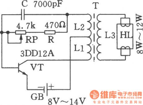
The chart shows the high frequency producing lamplighter circuit. It uses the 8V ~ 14V battery as energy source, and boosted by oscillation and then lights 6W ~ 12W fluorescent lamp. The transistor VT can use 3DD12A, D3D4D, 3DD5C, 3DDl5A and other low-frequency high-power transistor, it should be installed the 70mm × 40mm × 2mm of aluminum radiator when assembling; potentiometer RP should use a small wire wound type; frequency pulse transformer T can be self-made by ferrite magnetic tank with diameter in 22mm; coil L1 uses a high-strength magnet wire with 9 turns and diameter in lmm and rolled flatly on framework; feedback coil L2 uses a high-strength magnet wire with 8 turns and diameter in 0.3mm and rolled flatly on L1; coil L3 uses a 0.2mm enameled high-strength magnet wire with 900 turns and diameter in 0.2mm.
(View)
View full Circuit Diagram | Comments | Reading(903)
| Pages:1991/2234 At 2019811982198319841985198619871988198919901991199219931994199519961997199819992000Under 20 |
Circuit Categories
power supply circuit
Amplifier Circuit
Basic Circuit
LED and Light Circuit
Sensor Circuit
Signal Processing
Electrical Equipment Circuit
Control Circuit
Remote Control Circuit
A/D-D/A Converter Circuit
Audio Circuit
Measuring and Test Circuit
Communication Circuit
Computer-Related Circuit
555 Circuit
Automotive Circuit
Repairing Circuit