
Circuit Diagram
Index 2001
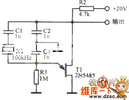
COLPITTS Oscillator Circuit Using Crystal
Published:2011/4/26 5:48:00 Author:Robert | Keyword: Crystal, COLPITTS Oscillator
View full Circuit Diagram | Comments | Reading(704)
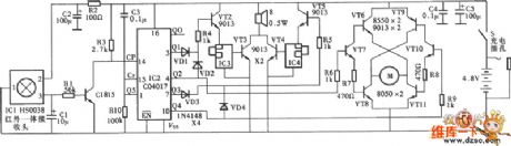
Ultrasonic Wave Remote Control Switch Circuit
Published:2011/4/26 5:49:00 Author:Robert | Keyword: Ultrasonic Wave, Remote Control Switch
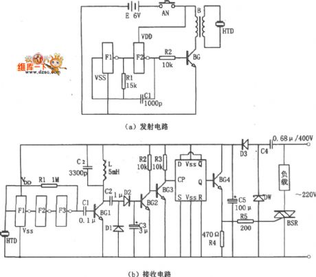
Ultrasonic Wave Remote Control Switch Circuit is shown below. (a)Transmitting Circuit. (b)Receiving Circuit.
(View)
View full Circuit Diagram | Comments | Reading(729)
Low-Cost Safe Timer Circuit
Published:2011/4/26 5:51:00 Author:Robert | Keyword: Low-Cost, Safe Timer
View full Circuit Diagram | Comments | Reading(698)
Pulse-Pulse Series Generator Circuit Composed Of CD4093,MC14093
Published:2011/4/26 5:52:00 Author:Robert | Keyword: Pulse-Pulse Series Generator
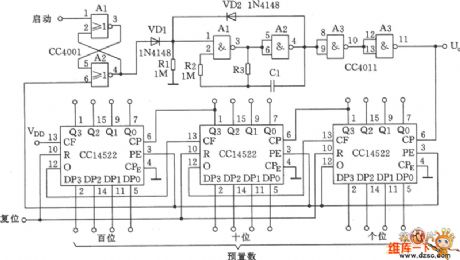
Pulse-Pulse Series Generator Circuit Composed Of CD4093,MC14093 is shown below:
(View)
View full Circuit Diagram | Comments | Reading(2370)
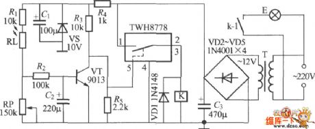
Light Control Street Lamp Circuit Using TWH8778
Published:2011/4/26 5:53:00 Author:Robert | Keyword: Light Control, Street Lamp
View full Circuit Diagram | Comments | Reading(813)
Infrared Control Faucet Circuit Using CX20106
Published:2011/4/26 5:54:00 Author:Robert | Keyword: Infrared Control Faucet
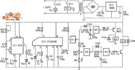
Infrared Control Faucet Circuit Using CX20106 is shown below:
(View)
View full Circuit Diagram | Comments | Reading(1943)
Touch Dimmer Circuit Composed Of LS7232
Published:2011/4/26 5:54:00 Author:Robert | Keyword: Touch, Dimmer
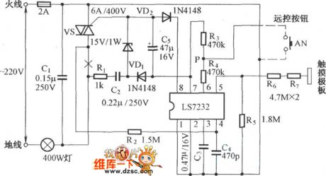
Touch Dimmer Circuit Composed Of LS7232 is shown below:
(View)
View full Circuit Diagram | Comments | Reading(3730)
Toyota Coaster bus combination instrument circuit diagram 3
Published:2011/4/26 20:02:00 Author:Rebekka | Keyword: Toyota Coaster bus , combination instrument
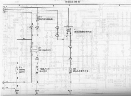
Toyota Coaster bus combination instrument circuit diagram is shown as above. (View)
View full Circuit Diagram | Comments | Reading(899)
555 Vco circuit with logarithmic characteristic
Published:2011/4/26 3:11:00 Author:Ecco | Keyword: 555 , Vco , logarithmic characteristic
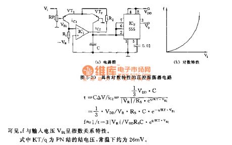
As shown in Figure 5-20, 555 and IC1, VT1, C etc. form VCO, the changing of input voltage VB1 causes the oscillation frequency of IC2 changing with logarithmic characteristics. VT1, VT2 are the same curve matching tube, because the base of VT2 is in zero potential, while VB1 changes, it can be equivalent to the VBE2 changing of VT2.
Capacitor charging current is the ic2, the relation between the input voltage VB1 and f has exponential characteristics. KT / q is the junction voltage of PN junction, it is about 26mV under room temperature.
(View)
View full Circuit Diagram | Comments | Reading(2230)
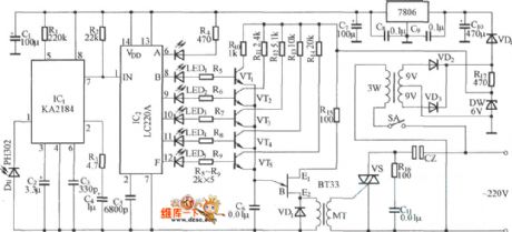
Fan speed controller-Electronic speed controller circuit
Published:2011/4/26 19:15:00 Author:Christina | Keyword: Fan speed controller, Electronic speed controller
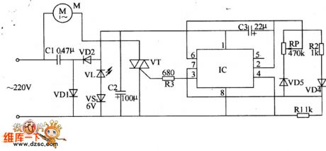
The Electronic fan speed control circuit is composed of the power supplier circuit, the controlled oscillator and the control-implement circuit, as the figure shown.
The power supplier circuit is composed of the capacitor Cl, the rectifier diode VDl, VD2, the filter capacitor C2, the power indicator LED VL and the zener VS.
The controlled oscillator is composed of the time-base integrated circuit IC, the resistor RI and R2, the capacitor C3, the potentiometer RP and the diode VD3, VD4.
The control-implement circuit is composed of the fan motor M, the thyristor VT, resistor R3 and the pin-3's in-circuit.
AC 220V voltage is reduced by the Cl, and rectified by the VD1 and VD2, then regulated by the VL and VS, at last this AC 220V voltage converted into 8V DC voltage.
(View)
View full Circuit Diagram | Comments | Reading(3758)
8W Mobile Small Size Emergency Lamp Circuit
Published:2011/4/26 7:23:00 Author:Robert | Keyword: 8W, Mobile, Small Size, Emergency Lamp
In this picture d1 is the charging pilot light. In the status of charging, as the battery voltage increased gradually, thebrightness of d1 would decrease gradually, until entirelygo out.
(View)
View full Circuit Diagram | Comments | Reading(1753)
XTR101 Thermocouple Input Circuit
Published:2011/4/26 8:05:00 Author:Robert | Keyword: Thermocouple
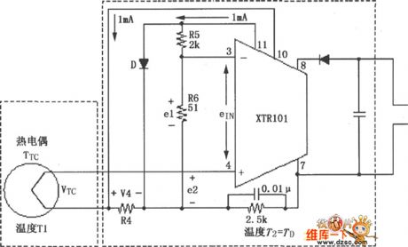
The circuit shows the thermocouple input circuit withtwo temperature zones and diode cold junction compensation. This circuit uses J-type thermocouple as temperature sensor, semiconductor diode Das cold junction temperature compensation to form the relative 0oC of the measurement, to measure the temperature, T1 temperature range is from 0 to 1000oC. The temperature of T2 is equal to the temperature TD of semiconductor diode D. When the measured temperature changes in the range of 0to 1000oC, J-type thermocouple will have a 58mV change. When the ambient temperature is +25oC, the typical value would be 1.28mV. Corresponding 0oC transmission current is 4mA, corresponding 1000oC transmission current is 20mA.
(View)
View full Circuit Diagram | Comments | Reading(1543)
Infrared Remote Control Toy Car Circuit
Published:2011/4/26 8:08:00 Author:Robert | Keyword: Infrared Remote Control, Toy Car
Infrared Remote Control Toy Car Circuit is shown below:
(View)
View full Circuit Diagram | Comments | Reading(1927)
555 Gate Pulse Generator Circuit
Published:2011/4/26 8:28:00 Author:Robert | Keyword: Gate Pulse Generator
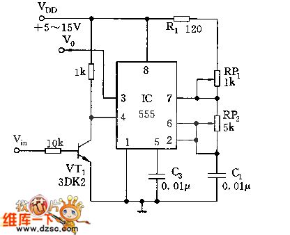
As shown, 555 and RP1, RP2, C1 compose the controllable multivibrator, its oscillation frequency depends on the constant time of R1, RP1, RP2, C1. But the oscillation depends on the voltage level of the input gate wave. When the Vln is high voltage level, VT1 is saturatedand conducted, the 4 foot of 555 is low voltage level,force the 555 resets, with no output; When the VlnO is low voltage level, VT1 closes, 555 is in a state of free oscillation, its 3 foot outputs the sequence oscillationsquare wave.
(View)
View full Circuit Diagram | Comments | Reading(2058)
XTR101 ELectrlcal Bridge InPut, Voltage Excitation Circuit
Published:2011/4/26 8:39:00 Author:Robert | Keyword: ELectrical Bridge InPut, Voltage Excitation
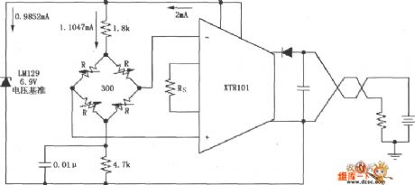
As shown, this circuit uses the voltage regulator tube LM129 to generate a 6.9V voltage reference, andthe 6.9V voltage reference provides 1.0147mA current to the electrical bridge. The electrical bridge could be variable resistance bridge type sensors like the pressure sensor etc.
(View)
View full Circuit Diagram | Comments | Reading(815)
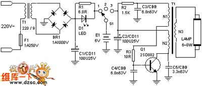
6W Mobile Small Size Emergency Lamp Circuit
Published:2011/4/26 9:41:00 Author:Robert | Keyword: 6W, Mobile, Small Size, Emergency Lamp
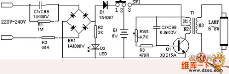
6W Mobile Small Size Emergency Lamp has the following features: small size and lightweight, high brightness, affordable, and it could be used generally in the country side or those areas of frequent power outages.
1.The circuit is shown below.
2.Principle of work
When the power plug connects to the 220V city power, the LED indicator would be lighted, at this time if turn the switch to the left side, the battery could be charging; when used outside, turn the switch to the right side, the emergency lamp starts to work, and the power could be closed while turning the switch to the left side.
(View)
View full Circuit Diagram | Comments | Reading(1511)
Infrared Remote Control Voltage Regulation Circuit
Published:2011/4/26 8:12:00 Author:Robert | Keyword: Infrared Remote Control, Voltage Regulation
Infrared Remote Control Voltage Regulation Circuit is shown below:
(View)
View full Circuit Diagram | Comments | Reading(538)
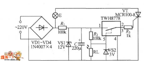
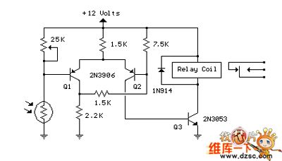
Light Control Street Lamp Switch Circuit
Published:2011/4/26 8:41:00 Author:Robert | Keyword: Light Control, Street Lamp, Switch
View full Circuit Diagram | Comments | Reading(765)
555 Gauge Head Frequency Meter Circuit
Published:2011/4/26 7:47:00 Author:Robert | Keyword: Gauge Head, Frequency Meter
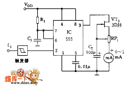
As shown, 555 and R1, C1 etc. compose a monostable delay circuit, input square wave signal or the square wave signal after the shaping of Schmitt trigger, trigger 555.The circuitrequires the time constant R1C1<Tin, Tin is the cycle time of input pulse signal. Or, input signal can not trigger 555 every time, and flip it.
VT1, RP1 areconstant current source, by adjusting RP1 make the mA meter to be full scaleata frequency. The relationship between the gauge head and frequency is: when the frequency become higher, as the duty cycle increases, the average current increases too, the pointer deflectionis larger; otherwise, the deflection is smaller.
(View)
View full Circuit Diagram | Comments | Reading(2158)
555 linear sawtooth wave generator circuit
Published:2011/4/26 2:50:00 Author:Ecco | Keyword: 555 , linear, sawtooth wave, generator
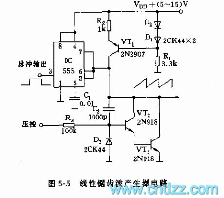
The circuit shown in Figure 5-5 is a sawtooth-wave circuit composed of the monostable trigger circuit, cross-flow circuit. VT1 and D1, D2, Rt form constant current charging circuit to make a good ramp linearity. The charging time constant of 555 monostable circuit is mainly decided by R2, C2. The circuit can produce linearity sawtooth in several HZ to 50kHz frequency range of broadband. This circuit can be used in a variable time base circuit, current - frequency converter and audio synthesizers and other occasions.
(View)
View full Circuit Diagram | Comments | Reading(4192)
| Pages:2001/2234 At 2020012002200320042005200620072008200920102011201220132014201520162017201820192020Under 20 |
Circuit Categories
power supply circuit
Amplifier Circuit
Basic Circuit
LED and Light Circuit
Sensor Circuit
Signal Processing
Electrical Equipment Circuit
Control Circuit
Remote Control Circuit
A/D-D/A Converter Circuit
Audio Circuit
Measuring and Test Circuit
Communication Circuit
Computer-Related Circuit
555 Circuit
Automotive Circuit
Repairing Circuit