
Circuit Diagram
Index 2016
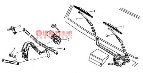
Nanjing IVECO light truck wiper circuit diagram
Published:2011/4/25 3:39:00 Author:Nicole | Keyword: light truck, Nanjing IVECO, wiper
View full Circuit Diagram | Comments | Reading(504)
MCP component MMl521XV internal block diagram and protection circuit
Published:2011/4/25 3:33:00 Author:Nicole | Keyword: MCP component
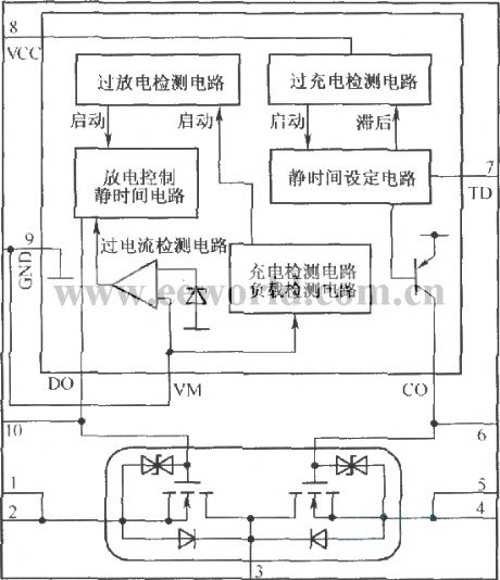
MCP is a multi-package produce, it can put the integrated protection circuit and charge-discharge circuit into the same package. The internal block diagram is shown as below:
(View)
View full Circuit Diagram | Comments | Reading(671)
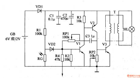
Dark room exposure timing light circuit(2)(BA225F)
Published:2011/4/24 22:58:00 Author:Nicole | Keyword: dark room, timing light
The figure is as shown, it is a dark room exposure timing light with novel timing IC. In figure, BA225F is a novel double timing IC produced by Toyo electric appliance, it contains two independent timers, this circuit only uses one of them, the timing time can be from a few milliseconds to a few minutes, the feature of it is: low power consumption(the typical value is 0.75mA), a few peripheral components, wide work voltage range and so on. (View)
View full Circuit Diagram | Comments | Reading(822)
xTimer V1.0
Published:2011/4/25 3:20:00 Author:Ecco | Keyword: Timer
Complete schematic is shown in Fig 2. The MCU is AT89C4051 with 11.0592MHz xtal. The MAX7219 needs only three signals, CLK, DIN and LOAD. These signals are software generated assembly code. You may learn how assembly code interface with c from the firmware. Since when power up, all port bits are logic high, so I chose the 7407, open collector to provide NPN O/C output. These output bits are suitable for opto-isolator driving. The sample output module is opto-triac, the MC3040. The input circuit is simple with current mode driving, say 15mA is enough for MC3040. The output triac having ZCS drives a 220V coil electromechanical relay. Since the relay contact provide NO and NC, so we can provide two function AC plugs, i.e., delay on for NO and delay off for NC contacts.
The sample schematic shown in Fig 2. has the relay circuit that uses opto triac driving a NO/NC relay! So I must change the firmware to let the output turn on when start timer and turn off when time is over. To do such changing, it needs to modify the source code and recompile it. I thought why don't try with sdcc. The people can modify the source code and do-it-yourself. (View)
View full Circuit Diagram | Comments | Reading(502)
Dark room exposure timing light circuit(1)
Published:2011/4/25 0:58:00 Author:Nicole | Keyword: Dark room, timing light
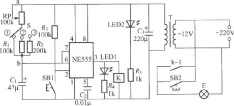
The figure is as shown, it is a dark room exposure timing light circuit which is suitable for black-and-white photographyblowing down Photos, the monostable trigger is composed of NE555 time base circuit and potentiometer RP, capacitance C. In normal times, the circuit is in resetting state, NE555's ③ foot output is low level, relay K is no action, exposing lamp E is off. LED2 is work indicating light, it can light up the calibrated disc of potentiometer RP. At this time, NE555 internal discharge tube turns on, capacitance C1 is short-circuited, it can not charge. K can adopt JZC-22F、DC12V small middle power electromagnetic relay. (View)
View full Circuit Diagram | Comments | Reading(980)
Night Light Saver V6
Published:2011/4/25 3:30:00 Author:Ecco | Keyword: Night Light , Saver , V6
Figure 1 shows complete hardware schematic of the Night Light Saver V6.0. The AC line was protected F1, a 1A fuse. Any short circuit caused by saver's components will blow the fuse. R1 and C1 limit current to the +5V zener diode, D3. R2 discharges capacitor C1 when power terminal of the circuit was opened. The super capacitor C2,+5V 0.01F filters DC supply. D4 acts as unidirectional switch for current supplied to MCU. BT1 is +3V 60mAH Ni-MH battery for backup the MCU when main power failed. The charging current is approx. 2mA with AC main lives. When main power failed, BT1 supplies approx. 4mA to the MCU. With fully charged, it could be able to provide backup time approx. 15Hrs. The MCU runs with +Vbackup. SW1 helps reset the MCU, in case of brownout voltage by BT1. C4 and internal pull-down resistor forms simple reset circuit. The MCU, 89C2051 runs with 3.579MHz Xtal. SW2 is for clock setting, when pressed, time will be 18:00. P3.7 drives tick LED with small sink current. R5, 4.7k limits less than one mA for D5. P3.0 provides 5Hz clock signal for calibration. The output bit is P1.6. It drives PNP transistor, Q1. R3 limits base current. R5 pull base pin to +V when P1.6 is logic '1' to fully turn off Q1. R4 limits DC current injected to Q2, MAC97 small triac. LP1 is incandescent 25W lamp. The (View)
View full Circuit Diagram | Comments | Reading(536)
Easy-Downloader V1.1 with SDCC
Published:2011/4/25 3:27:00 Author:Ecco | Keyword: Easy-Downloader , SDCC
The hardware has a bit change at rs232 level converter. Now the circuit uses a popular rs232 level converter, MAX232. Also I cut the bridge diode at the DC input, now I use only one diode to prevent wrong polarity of a given DC adapter.
18 March 2004: found hardware schematic error at MAX232. The error is that pin 2 on the D-SUB 9 connector must be connected to pin 13 on the MAX232, not pin 8. The error had reported by Henrik Olesen, student at the University of Southern Denmark. (View)
View full Circuit Diagram | Comments | Reading(573)
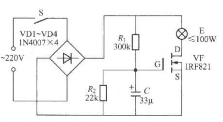
Incandescent lamp life extension switch circuit
Published:2011/4/25 1:05:00 Author:Nicole | Keyword: incandescent lamp, life extension, switch
View full Circuit Diagram | Comments | Reading(560)
MAX846A pin array diagram
Published:2011/4/25 3:26:00 Author:Nicole | Keyword: pin
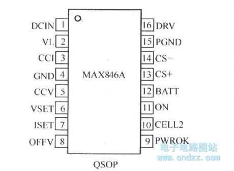
MAX846A is a low cost and multifunction battery charge controllor produced by Maxim Company, its pin array diagram is shown as below:
(View)
View full Circuit Diagram | Comments | Reading(599)
Mitsubishi Pajero light off-road vehicle electric control rearview mirror wiring circuit diagram
Published:2011/4/25 2:57:00 Author:Rebekka | Keyword: Mitsubishi Pajero, light off-road vehicle , electric control , rearview mirror wiring
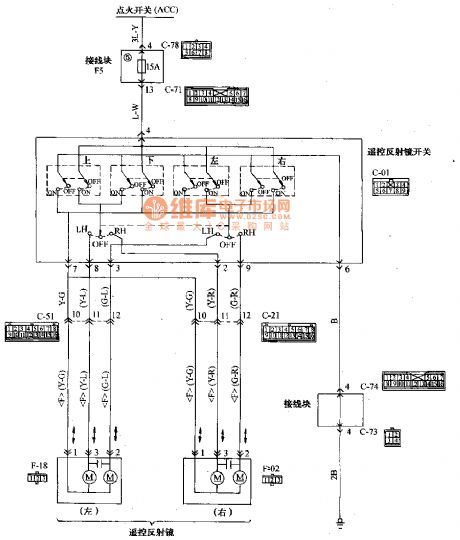
Wiring Color B: Black LG: light green G: Green L: Blue W: White Y: Yellow SB: sky blue BR: Brown 0: Orange GR: Gray R: red p: Pink V: Purple
Mitsubishi Pajero light off-road vehicle electric control rearview mirror wiring circuit diagram is shown as above. (View)
View full Circuit Diagram | Comments | Reading(4525)
Composed of MOSFETT symmetrical power amplifier circuit diagram
Published:2011/4/25 2:24:00 Author:Rebekka | Keyword: MOSFETT, symmetrical power amplifier

Figure 1 is symmetrical power amplifier circuit constituted by the MOSFETT. The circuit uses a single-ended input mode push-pull output Class A, the output power is lOW. (View)
View full Circuit Diagram | Comments | Reading(4487)
Toyota Kauste bus wireless and gramophone, safety door circuit wiring circuit diagram
Published:2011/4/25 3:21:00 Author:Nicole | Keyword: Toyota, Kauste bus, wireless, gramophone, safety door
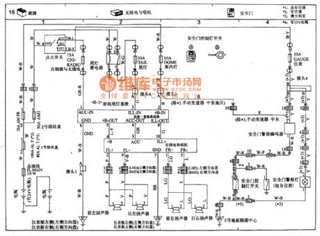
View full Circuit Diagram | Comments | Reading(1077)
Trickle charge simple schematic diagram
Published:2011/4/25 2:04:00 Author:Nicole | Keyword: Trickle charge
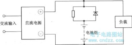
The battery is in parallel with load, and the battery is also connected to power supply. Under normal circumstances, the DC power supply is as the power supply of load, it charges to battery with trickle mode, only the load changes greatly, and the DC power supply terminal voltage is lower than battery terminal voltage or the DC power supply stop supplying, the battery will discharge to load. Under this method, the charge current is decided by the used module. It is usually used in the occasions where the emergency power supply, standby power supply or electronic watch can not be cut off. (View)
View full Circuit Diagram | Comments | Reading(1024)
Vehicle flashing lights controller 6
Published:2011/4/21 4:19:00 Author:Ecco | Keyword: Vehicle , flashing lights , controller
(View)
View full Circuit Diagram | Comments | Reading(648)
5V regulated power supply composed of MC1460G integrated regulator
Published:2011/4/25 3:17:00 Author:Nicole | Keyword: 5V regulated power supply, integrated regulator
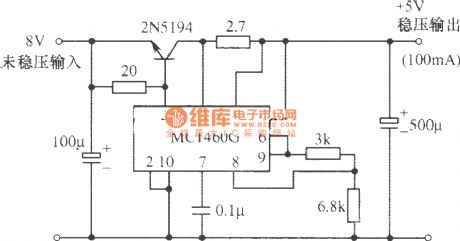
View full Circuit Diagram | Comments | Reading(618)
MAX846A most typical application circuit (charge circuit)
Published:2011/4/25 3:15:00 Author:Nicole
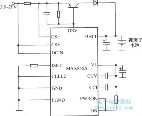
MAX846A charges to lithium ion battery as an undependent limited voltage current source. (View)
View full Circuit Diagram | Comments | Reading(749)
Automobile headlight-HID light igniter
Published:2011/4/25 2:26:00 Author:Nicole | Keyword: automobile headlight, igniter
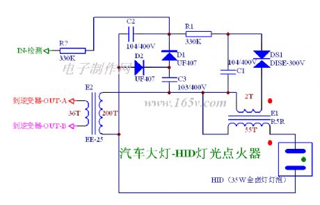
View full Circuit Diagram | Comments | Reading(1581)
CMos drive circuit used in LCD
Published:2011/4/25 2:49:00 Author:Nicole | Keyword: LCD, CMos drive
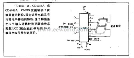
CD4054A, CD4055A or CD4056A CMOS directly drive 7 segment LCD digit, because this circuit has the characteristic of internal PWL movement, this characteristic is needed by 30V peak AC singal, the singal is used to transform 5V input logic into drive state. (View)
View full Circuit Diagram | Comments | Reading(824)
Flashing trigger circuit
Published:2011/4/25 2:39:00 Author:Nicole | Keyword: flashing, trigger
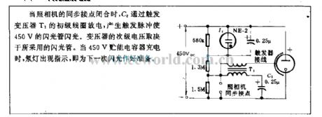
When the synchronous contact of camera is closed, C2 discharges by triggering the primary coil of transformer T1, it will produce a trigger pulse to make 450V flashtube flash. The secondary voltage of transformer is determined by the adopted flashtube. When 450V energy storage capacitor is charging, neon light will indicate to get ready for the next flashing. (View)
View full Circuit Diagram | Comments | Reading(504)
MAXTl3 switch mode application circuit
Published:2011/4/25 3:10:00 Author:Nicole | Keyword: switch mode
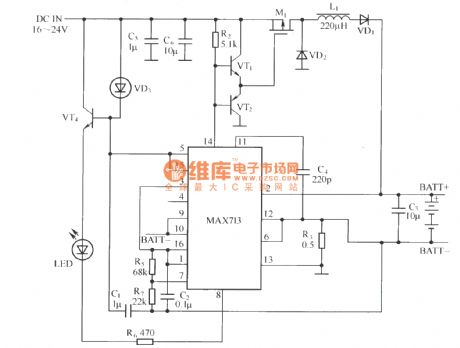
View full Circuit Diagram | Comments | Reading(436)
| Pages:2016/2234 At 2020012002200320042005200620072008200920102011201220132014201520162017201820192020Under 20 |
Circuit Categories
power supply circuit
Amplifier Circuit
Basic Circuit
LED and Light Circuit
Sensor Circuit
Signal Processing
Electrical Equipment Circuit
Control Circuit
Remote Control Circuit
A/D-D/A Converter Circuit
Audio Circuit
Measuring and Test Circuit
Communication Circuit
Computer-Related Circuit
555 Circuit
Automotive Circuit
Repairing Circuit