
Circuit Diagram
Index 2005
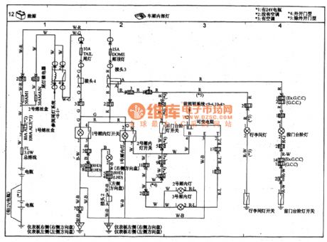
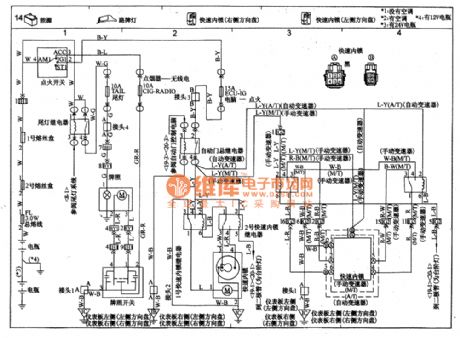
TOYOTA COASTER carriage interior light circuit wiring circuit diagram
Published:2011/4/26 3:09:00 Author:Nicole | Keyword: TOYOTA COASTER, carriage, interior light
View full Circuit Diagram | Comments | Reading(1252)
Using LB1405 as DC power supply circuit diagram
Published:2011/4/26 3:14:00 Author:Rebekka | Keyword: DC power supply
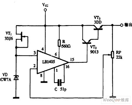
Using LB1405 as DC power supply circuit diagram is shown as above. (View)
View full Circuit Diagram | Comments | Reading(1259)
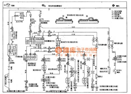
TOYOTA COASTER coach direction signal light and hazard warning lantern circuit wiring circuit diagram
Published:2011/4/26 3:13:00 Author:Nicole | Keyword: TOYOTA COASTER, coach, direction signal light, hazard warning lantern
View full Circuit Diagram | Comments | Reading(1777)
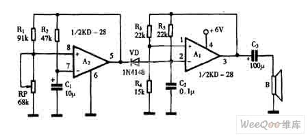
Using LB1405 as the audio signal amplifier circuit diagram
Published:2011/4/26 3:16:00 Author:Rebekka | Keyword: audio signal amplifier
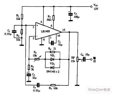
Using LB1405 as the audio signal amplifier circuit diagram is shown as above. (View)
View full Circuit Diagram | Comments | Reading(2200)
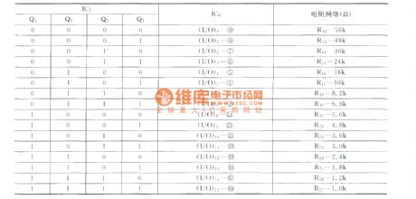
CD4067 input and output relationship circuit
Published:2011/4/20 1:18:00 Author:Rebekka | Keyword: input and output relationship
View full Circuit Diagram | Comments | Reading(890)
Using LB1413 as electronic thermometer circuit diagram
Published:2011/4/26 3:13:00 Author:Rebekka | Keyword: electronic thermometer

Using LB1413 as electronic thermometer circuit diagram is shown as above. (View)
View full Circuit Diagram | Comments | Reading(2006)
Using BISS0001 infrared sensor automatic nighttime lighting control circuit diagram
Published:2011/4/19 22:19:00 Author:Rebekka | Keyword: Infrared sensor, Automatic nighttime lighting
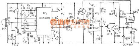
Circuit is shown in the figure, which is based on infrared sensing ASIC BISS0001 core composition, coupled with its external PIR pyroelectric infrared sensor and light control circuit. You can make one for the warehouse, shopping malls, corridors, other occasions, the automatic aisle lighting, lighting or security systems. (View)
View full Circuit Diagram | Comments | Reading(8904)
TOYOTA COASTER coach road sign light, fast interlocking circuit wiring circuit diagram
Published:2011/4/26 3:06:00 Author:Nicole | Keyword: TOYOTA COASTER, coach, road sign light, fast interlocking
View full Circuit Diagram | Comments | Reading(1188)
Using KD-28 to make "beep" sound generator circuit diagram
Published:2011/4/26 3:08:00 Author:Rebekka | Keyword: sound generator
Using KD-28 to make beep sound generator circuit diagram is shown as above. (View)
View full Circuit Diagram | Comments | Reading(913)
Using LM386 as BTL amplifier circuit diagram
Published:2011/4/26 3:11:00 Author:Rebekka | Keyword: amplifier circuit
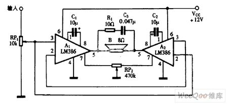
Using LM386 as BTL amplifier circuit diagram is shown as above. (View)
View full Circuit Diagram | Comments | Reading(10764)
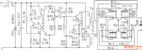
Music control colored light circuit diagram
Published:2011/4/20 9:45:00 Author:Rebekka | Keyword: Music control colored light

This circuit only use three channels for acousto-optic conversion, as the Yin additional stereo equipment. To remove the heavy DC load, the circuit use triac instead of an ordinary silicon. Capacitance Road and audio transformer T2 ~ T ¥ is parallel. They are transferred to high, medium and low frequency range. Triac TRIAC Q2 ~ Q1 turn on the colored bulbs inserting into the outlet SO.
(View)
View full Circuit Diagram | Comments | Reading(1661)
1024kHz and 4kHz square-wave output circuit
Published:2011/4/21 5:14:00 Author:Ecco | Keyword: 1024kHz , 4kHz , square wave, output
The circuit SJT is a 1024kHz warming crystal oscillator. Circuit is shown as the chart. As its output signal level is low, so the following transistor VTl is used as the buffer amplifier. The base bias resistor R2 of VTl, the load resistor R3, the emitter resistor R4 form the negative feedback resistor which is used to stabilize the DC operating point of VTl. The voltage-regulator diodes VDl and VD2, capacitor Cl form a regulator, filter circuit to reduce the influence on the frequency of the crystal SJT from supply voltage fluctuation. Resistor Rl and potentiometer RP provide bias voltage to the TCXO, adjusting the RP can fine-tune crystal frequency.
(View)
View full Circuit Diagram | Comments | Reading(1239)
The double-T sinusoidal oscillator with stable output composed of LM170
Published:2011/4/20 21:48:00 Author:Ecco | Keyword: double-T, sinusoidal oscillator , stable output

The chart shows the double-T sinusoidal oscillator circuit with stable output. The circuit uses the automatic gain control amplifier LM170 to stabilize its amplitude. This approach can guarantee the waveform distortion. Even if the double-T loop and the amplifier gain changes, it can ensure the output amplitude constant. Component values can compensate for 40dB changes. 100k potentiometer is used to change the threshold level of automatic gain control, thereby changing the output level. Circuit oscillation frequency: f0 = 1/2π, RC uses the value of the marked components in the figure, the oscillation frequency is approximately 1kHz.
(View)
View full Circuit Diagram | Comments | Reading(1673)
Battery charging NC constant current source circuit diagram
Published:2011/4/26 3:02:00 Author:Rebekka | Keyword: Battery charging, NC constant current source
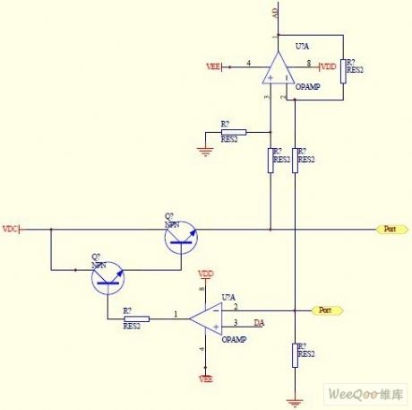
It is a numerical control constant current source designed for the charge of battery. D / A converter outputs a voltage to the bottom of the op amp inverting input, the circuit current I = Uad / sampling resistor, the two PORT are used to access the battery + and - poles. The magnification of the amplifier circuit is 1/4. It is used for measuring battery voltage. The 2 adjusted tubes are 3dd13 and 3dd15.
(View)
View full Circuit Diagram | Comments | Reading(2191)
1kHz signal generator
Published:2011/4/20 5:19:00 Author:Ecco | Keyword: 1kHz, signal generator
This circuit can generate lkHz signalwith 3 kinds of output level. It can be used for testing and repairing communications equipment,
and finding the failure point of TV sets, stereos, radios and other low-frequency amplifier circuit quickly and accurately. Therefore, it is ideal signal source for electronic equipment. Selection components: Resistor uses RJ-0.125, capacitor uses CBM, electrolytic capacitor uses CDX, switch Sl: KNX (2 × 1), S2: JT360 (small pull key). Transformers Tl, T2: using MTT25 ferrite pot, the L1-2 of T1 uses Φ0.09mm high-strength wire with 1540 turns, L3-4 uses 0.09mm high strength wire with 150 turns, L5-6 uses Φ0.09mm high strength wire with 330 turns; the L1-2 of T2 uses Φ0.09mm high-strength wire with 1528 turns, L3-4 uses Φ0.09mm high-strength wire with 162 turns, L5-6 uses 0.09mm high strength with wins wire with 540 turns.
(View)
View full Circuit Diagram | Comments | Reading(604)
TA8859 pincushion correction circuit diagram
Published:2011/4/24 3:26:00 Author:Rebekka | Keyword: pincushion correction circuit
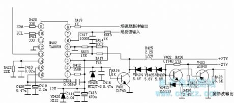
Field excitation pulse input
N402 (TA8859) 2 foot parabolic wave output voltage is amplified by the V401 ~ V403, and outputs the parabolic wave by V403 collector. It will be sent to the line deflection coil and change the flow through the line deflection coil current. That is, completion of the East / West pincushion correction. The east / west pincushion correction is sent to bus adjustment mode.
Pin 1: 3.7V-- high stability detection input Pin 2: 1.1V-- something the school pillows parabolic wave output Pin 3: 12.0V-- +12 V voltage input Pin 4: 5.5V-- something the school pillows feedback input side Pin 5: 0V - to Pin 6: 4.2V-- the input field scanning FeedbackPin 7: 0V Pin 8: 2.1V-- Field sawtooth voltage output Pin 9: 4.8V-- Bus cable connector Pin 10: 4.8V-- Bus clock line Pin 11 connector: 0V- - empty pin Pin 12: 0V - to Pin 13: 4.4V-- field excitation pulse signal input Pin 14: 3.8V-- external pulse shaping filter side Pin 15: 6.0V-- field scanning ramp voltage to form side Pin 16: 3.0V-- end automatic gain control filter
(View)
View full Circuit Diagram | Comments | Reading(1750)
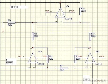
800Hz oscillator
Published:2011/4/20 5:43:00 Author:Ecco | Keyword: 800Hz , oscillator
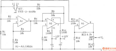
The circuit shown in the chart is 800Hz oscillator with the advantages of simple circuit, high accuracy of frequency and stable output level. It consists of four operational amplifiers Manifold Al ~ A3 (LM324) and the 800Hz oscillator composed of SJT (YYZ-2-800Hz) tuning fork. When 800Hz oscillation signal produced by SJ1 being added to two-stage operational amplifier formed by A1 and A2, it will be output by pin ⑦ and become positive feedback frequency signal through the resistor R5, SJT. Then the amplified 800Hz is amplified by A3 again. And it will be sent by pin ⑧ to the potentiometer RP, the adjustable arm can output (Uo) 800Hz sine wave signal. Among them, adjusting the potentiometer RP will meet the output level of 0dB/600Ω, adjustable range is ± 3db. (View)
View full Circuit Diagram | Comments | Reading(1260)
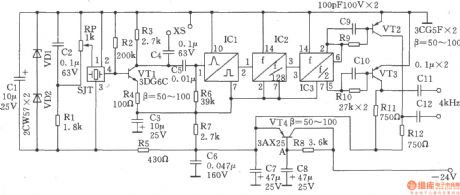
12kHz signal generator
Published:2011/4/20 4:28:00 Author:Ecco | Keyword: 12kHz, signal , generator
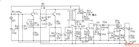
The 12kHz signal generator is shown as the chart, it is composed of the crystal oscillator and the alarm circuit. Oscillator output amplitude is stable, changing <± 0.26dB. Selection components: transistor VTl, VT3: 9014,65 ≤ β ≤ 115; VT2, VT4: 3DGl308, 60 ≤ β ≤ 85. Thermistor RT: RRWl-2 type. Crystal SJT: BE42-12kHz. The transformer T uses MXD-2000 ferrite, the core is GV36X22, Ll-2 uses Φ0.17mm high-strength wire with 57 turns, L3-4 uses Φ0.17mm high-strength wire with 37 turns. Models of light-emitting diode VD3 is not limited. Nominal power of resistor selects 1/8W metal film resistors. Other component values are shown in Figure, there's no special requirements.
(View)
View full Circuit Diagram | Comments | Reading(777)
Pressure well draw off water remind circuit composed of CIC3830
Published:2011/4/26 2:41:00 Author:TaoXi | Keyword: Pressure well, draw off water, remind circuit

The pressure well draw off water remind circuit is as shown. This circuit is composed of the water level probe A, music IC CIC3830, and the speaker.etc.
If the water level is higher than probe A, BG2 turns on, the CIC3830 starts working, the output music signal is amplified by BG1 and then promote the sound speaker Y to remind the master to draw off water. If the water level is lower than probe A, BG2 turns off, the CIC3830 stops working to send out music signal.
If you don't draw off the water, the circuit will continue to play the music until you draw off the water, so we can avoid the well pipe damaged in the cold winter. (View)
View full Circuit Diagram | Comments | Reading(806)
Pressure sensor excitation circuitry diagram
Published:2011/4/26 2:50:00 Author:Nicole | Keyword: pressure sensor
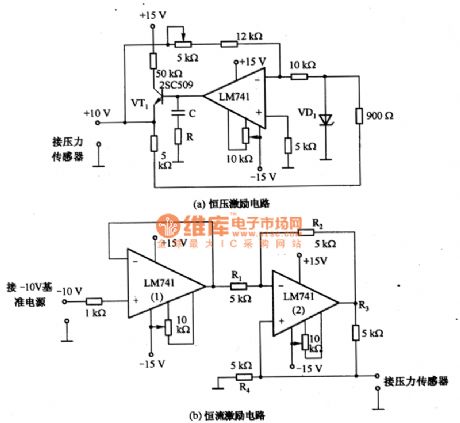
The figure 1 is a pressure sensor excitation circuit. Figure1(a) is generic constant voltage excitation circuit, it is composed of Zener diode VD1, operational amplifier and LM741; Figure1(b) is constant current excitation circuit, its stability is decided by Rl一R4, so it should choose the resistance with low temperature coefficient. The temperature stability of this excitation circuit should be designed to 1/100 of sensor. Such as the temperature stability of sensor is 0.1%, then the excitation circuit is 0.001%.
(View)
View full Circuit Diagram | Comments | Reading(1946)
| Pages:2005/2234 At 2020012002200320042005200620072008200920102011201220132014201520162017201820192020Under 20 |
Circuit Categories
power supply circuit
Amplifier Circuit
Basic Circuit
LED and Light Circuit
Sensor Circuit
Signal Processing
Electrical Equipment Circuit
Control Circuit
Remote Control Circuit
A/D-D/A Converter Circuit
Audio Circuit
Measuring and Test Circuit
Communication Circuit
Computer-Related Circuit
555 Circuit
Automotive Circuit
Repairing Circuit