
Circuit Diagram
Index 2010
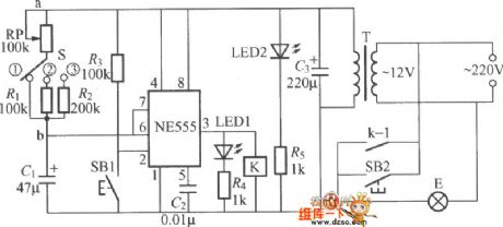
Radar energy-saving lamp circuit diagram
Published:2011/4/20 5:25:00 Author:Rebekka | Keyword: Radar energy-saving lamp
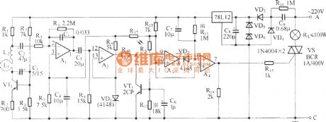
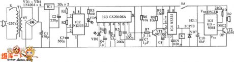
Radar energy-saving lamp is a human microwave sensing switch. When someone walked into the effective range, the lights turn on automatically, after a period delay of the automatic shut down. If the body in the range of activities, sustained light will lighten. Radar energy-saving lamps also have light control function, so that lights only at night. Figure is a radar-type energy-saving lamp circuit diagram. (View)
View full Circuit Diagram | Comments | Reading(1855)
Wind Turbine Schematic Circuit
Published:2011/4/25 7:26:00 Author:Robert | Keyword: Wind Turbine
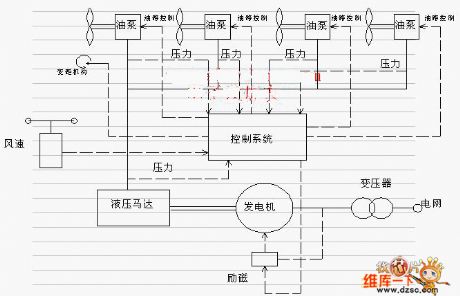
Wind Turbine SchematicCircuit is shown above. (View)
View full Circuit Diagram | Comments | Reading(1313)
400Hz Sine Wave Circuit Using Light-Emitting Diode And Operational Amplifier
Published:2011/4/25 7:27:00 Author:Robert | Keyword: Light-Emitting Diode, Operational Amplifier, 400Hz, Sine Wave
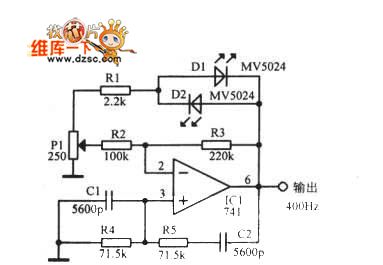
400Hz Sine Wave Circuit Using Light-Emitting Diode And Operational Amplifier is shown below:
(View)
View full Circuit Diagram | Comments | Reading(1045)
Practical Numerical Control Or Inverter Circuit
Published:2011/4/25 7:25:00 Author:Robert | Keyword: Numerical Control, Inverter
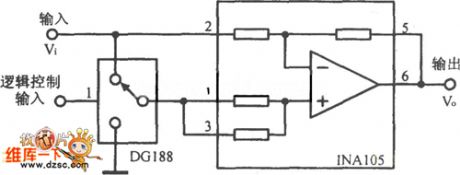
Practical Numerical Control Or Inverter Circuit is shown below:
(View)
View full Circuit Diagram | Comments | Reading(442)
75Ω Impedance Linear Amplification Circuit Consists Of RF2320
Published:2011/4/24 6:02:00 Author:Robert | Keyword: 75Ω, Impedance Linear Amplification

75Ω Impedance Linear Amplification Circuit Consists Of RF2320 is shown below. J1 and J2are 75Ω Connectors.
(View)
View full Circuit Diagram | Comments | Reading(596)
MAX6303/MAX6302/MAX6301/MAX6304 Application Circuit
Published:2011/4/22 5:12:00 Author:Robert | Keyword: Application
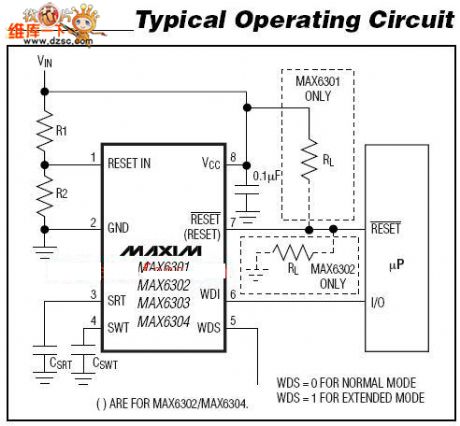
The MAX6303/MAX6302/MAX6301/MAX6304 application circuit is shown above. (View)
View full Circuit Diagram | Comments | Reading(876)
MAX8819 Application Circuit
Published:2011/4/22 5:12:00 Author:Robert | Keyword: Application
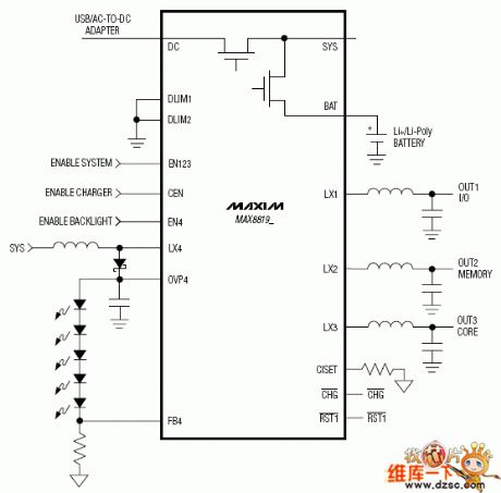
MAX8819 Application Circuit is shown below:
(View)
View full Circuit Diagram | Comments | Reading(655)
TEA2107 Application Circuit
Published:2011/4/22 5:12:00 Author:Robert | Keyword: Application
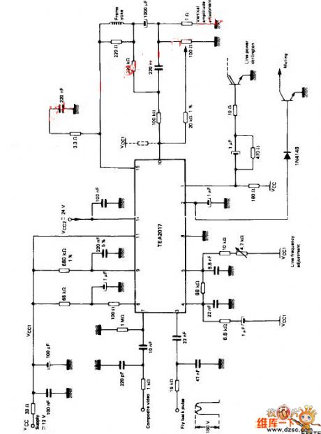
TEA2107 application circuitis shown above. (View)
View full Circuit Diagram | Comments | Reading(990)
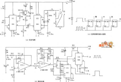
Electric single-girder crane remote control circuit diagram
Published:2011/4/24 11:42:00 Author:Rebekka | Keyword: Electric single-girder, crane remote control
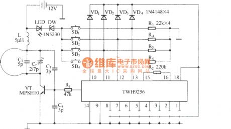
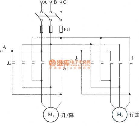

Electric single-girder cranes is also known as electric hoist. It is commonly used in small factories lifting handling equipment. Usually it is always used with drag line switching noytoperation, which is not very convenient. The circuit is composed of radio remote control radio remote control component TWH9236/38 circuit. It is shown as above. Remote control transmitter is the finished piece, that TWH9236, the internal schematic is shown as above.
Remote control receiver control circuit is shown as below.
(View)
View full Circuit Diagram | Comments | Reading(5315)
Infrared Ray Remote Control Color Light Controller Circuit
Published:2011/4/22 2:58:00 Author:Christina | Keyword: Infrared Ray, Remote Control, Color Light Controller
The Infrared Ray Remote Control Color Light Controller Circuit is as shown:
(View)
View full Circuit Diagram | Comments | Reading(2287)
Single wireless remote control switch circuit diagram(TDC1808/TDC1809)
Published:2011/4/24 11:53:00 Author:Rebekka | Keyword: wireless remote control
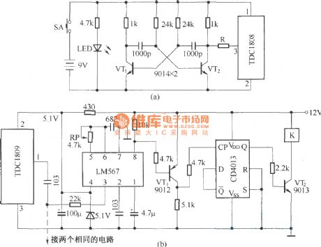
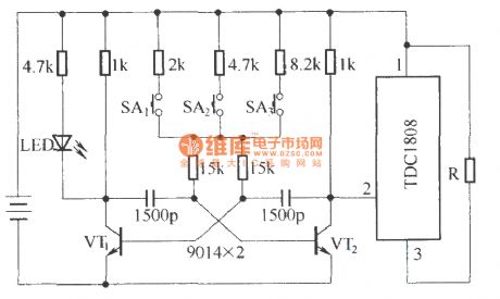
For the three-way wireless remote control switch, the transmitter is shown as below, receive circuit is the same with the single circuit.
(View)
View full Circuit Diagram | Comments | Reading(2884)
Circuit Diagram of Infrared Ray Remote Anti-theft Alarm
Published:2011/4/21 1:20:00 Author:Tina | Keyword: Infrared Ray, Remote Anti-theft, Infrared Ray Remote Anti-theft Alarm
The Circuit Diagram of Infrared Ray Remote Anti-theft Alarm is as shown:
Welcome to reprint, the information is from the Weiku Electronic Market Network (www.dzsc.com). (View)
View full Circuit Diagram | Comments | Reading(1175)
Circuit Diagram of 555 Inductive-Switch Power Supplier
Published:2011/4/21 1:32:00 Author:Tina | Keyword: Inductive-Switch, Power Supplier
The figure as shown, 555 and R1、R2、C1 build up the astable multivibrator, the oscillation frequency is about 10KHZ, the duty cycle is nearly 50%. VT2、VT3 are used as the switch to amplify the current. When the oscillating square wave is high, VT2, VT3 will be conduction and then discharge to the LC; when the current is low, the energy storage of L supply power to the burden by the freewheeling diode circuit. When the condition is overvoltage, DW will breakdown and VT1 conduction saturated, C<0.7V, this process play the fuction of regulator and dynamic balance.
Welcome to reprint, the information is from the Weiku Electronic Market Network (www.dzsc.com).
(View)
View full Circuit Diagram | Comments | Reading(573)
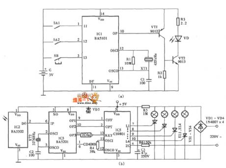
Against electric shock language warning circuit diagram
Published:2011/4/24 20:50:00 Author:Rebekka | Keyword: Against electric shock, language warning
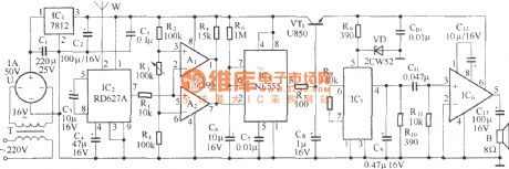
This circuit can be used to warn against electric shock for transformation and distribution facilities, when someone enters the detection range of the microwave device, the circuit will be issued the sound of on electricity, do not close . Here is the circuit.
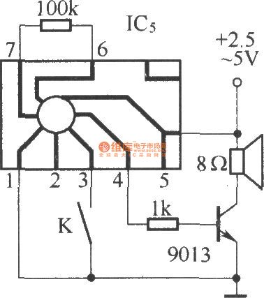
IC5 is software package language integrated circuit. Here are the shape and connection diagram.
(View)
View full Circuit Diagram | Comments | Reading(1284)
Circuit Diagram of Third-order Asymmetric Filter
Published:2011/4/21 1:26:00 Author:Tina | Keyword: Third-order, Asymmetric
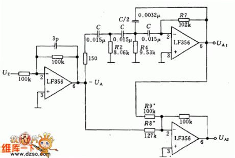
The Third-order Asymmetric Filter has two output channels (UA1 and UA2), UA1 is the high-pass filtered output channel and the UA2 is the low-pass filtered output channel. The circuit is as shown:
(View)
View full Circuit Diagram | Comments | Reading(574)
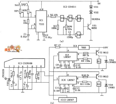
Circuit Diagram of Dual-channel Infrared Ray Remote Control Switch
Published:2011/4/21 9:14:00 Author:Christina | Keyword: Dual-channel, Infrared Ray Remote Control
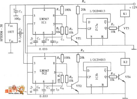
The Circuit Diagram of Dual-channel Infrared Ray Remote Control Switch is as shown:
Welcome to reprint, the information is from the Weiku Electronic Market Network (www.dzsc.com). (View)
View full Circuit Diagram | Comments | Reading(1470)
Circuit Diagram of Multi-function Infrared Ray Remote Controller
Published:2011/4/21 1:24:00 Author:Tina | Keyword: Multi-function, Infrared Ray Remote Controller
The Circuit Diagram of Multi-function Infrared Ray Remote Controller is as shown:
Welcome to reprint, the information is from the Weiku Electronic Market Network (www.dzsc.com). (View)
View full Circuit Diagram | Comments | Reading(1301)
Circuit Diagram of 8-channel Infrared Ray Remote Control
Published:2011/4/21 1:23:00 Author:Tina | Keyword: 8-channel, Infrared Ray Remote
The Circuit Diagram of 8-channel Infrared Ray Remote Control is as shown: (View)
View full Circuit Diagram | Comments | Reading(1862)
Mining Light Circuit
Published:2011/4/22 4:29:00 Author:Christina | Keyword: Mining Light
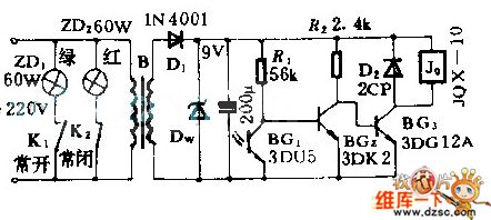
The pilot lamp which is installed in scene can helps the driver to determine the situation behind car. The phototransistor is used as optical signal sensor, when light shines on the photodiodor, relay J0 closes and one of the normal-open contact close too, if the green light open, it means that there is no obstacle behind car. If there are some obstacles block the light, relay J0 does not close, red light opens.
(View)
View full Circuit Diagram | Comments | Reading(654)
Darkroom Exposure Timer Lamp Circuit
Published:2011/4/22 4:23:00 Author:Christina | Keyword: Darkroom Exposure, Timer Lamp
The darkroom exposure timer lamp circuit is as shown, the ne555 time base circuit and the potentiometer rp, capacitor c form the single-stable trigger. Usually the circuit is in reset state, pin-3 of ne555 send out the low-level current, relay K does not operate, exposure light E does not shine. LED led2 is designed as the indicator light, this indicator lightilluminates the dial of potentiometer rp. At this point the internal discharge of ne555 is conducted, capacitor C1 is shorted and can not be charged. k can be the small medium-power electromagnetic relay such as jzc-22f and dc12v.
(View)
View full Circuit Diagram | Comments | Reading(730)
| Pages:2010/2234 At 2020012002200320042005200620072008200920102011201220132014201520162017201820192020Under 20 |
Circuit Categories
power supply circuit
Amplifier Circuit
Basic Circuit
LED and Light Circuit
Sensor Circuit
Signal Processing
Electrical Equipment Circuit
Control Circuit
Remote Control Circuit
A/D-D/A Converter Circuit
Audio Circuit
Measuring and Test Circuit
Communication Circuit
Computer-Related Circuit
555 Circuit
Automotive Circuit
Repairing Circuit