
Circuit Diagram
Index 2014
Telephone control automatic lighting circuit 1
Published:2011/4/25 4:30:00 Author:May | Keyword: Telephone control, automatic lighting
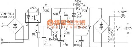
The diagram shows telephone control automatic lighting circuit. At night, when telephone rings or master takes up telephone transmitter dialing, the light can lighten; when telephone ringer stopped (no one listen) or on-hook, it can delay 10~40s, then the light can die out itself. Moreover, this circuit also set a light triggering button. The light can lighten about 40s only by pressing the button. (View)
View full Circuit Diagram | Comments | Reading(1530)
Telephone control automatic lighting circuit 2
Published:2011/4/25 4:37:00 Author:May | Keyword: Telephone control, automatic lighting
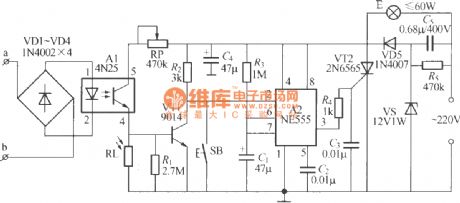
The diagram shows telephone automatic light composed of NE555 time base circuit and optical coupler. At night, when you need to make a telephone call, the light can lighten itself, it can delay 10~40s after on-hook, then the light can die out itself. Moreover, this circuit also set a triggering button. Ordinarily, when you need to lighten, the light can self lighten about 1min only by pressing the button. (View)
View full Circuit Diagram | Comments | Reading(745)
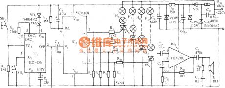
5GM168 "mandarin duck jump" lantern loop control with birdsong circuit
Published:2011/4/25 4:40:00 Author:May | Keyword: lantern loop control, birdsong
View full Circuit Diagram | Comments | Reading(529)
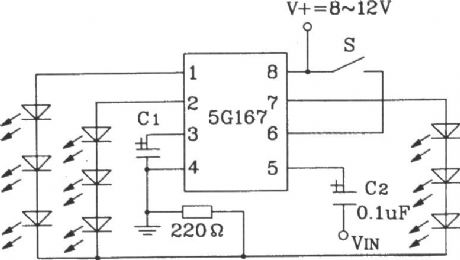
Typical application circuit of 5G167 synchronous Lantern ring control integrated circuit
Published:2011/4/25 4:42:00 Author:May | Keyword: synchronous Lantern, ring control, integrated circuit
View full Circuit Diagram | Comments | Reading(809)
Low frequency signal generator with high performance and composed of F007
Published:2011/4/21 6:00:00 Author:Ecco | Keyword: Low frequency, signal generator , high performance
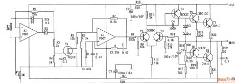
The chart shows the low frequency signal generator circuit with high performance. The circuit is characterized by a steady increase performance, high output power, low waveform distortion. It is an ideal source of low frequency measurement signal. In the figure, the op amp A and its feedback network form a typical Wien oscillator, the oscillation frequency: f0 = 1/2. The output of RCA2 connecting to the OCL complementary push-pull amplifier may improve the circuit's load capacity. Operational amplifier A1 connected as the negative half-wave amplifier, and it forms a steady negative feedback circuit by combining with W1, R4, C1, T1 and other components. Potentiometer W1 adjusts the output rate, and it is used as sampler in the feedback loop. In order to ensure small waveform distortion, generally it should make R1C1 ≥ 20πRC. The circuit output amplitude is 0.5 ~ 5V, output current is 0 ~ 1A, the frequency adjustment range is 10Hz ~ 10kHz, the output resistance is less than or equal to 0.05Ω, harmonic distortion is less than 0.1%.
(View)
View full Circuit Diagram | Comments | Reading(3489)
The low frequency various waveforms generator(741)
Published:2011/4/22 2:58:00 Author:Ecco | Keyword: low frequency, various waveforms , generator
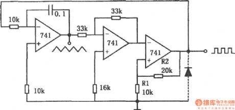
The chart shows a low frequency various waveforms generator circuit. The circuit can output two waveforms, the triangular wave and square wave. In the circuit, the first level is a standard integrator; second level is the inverter with gain in 1; the third level is a comparator with hysteresis. In the third stage without the diode, the circuit output is positive, the integrator output is negative syncline wave, which will be positive by reverse-phase helical wave and added to the comparator. When the ramp rate reaches the comparator threshold level Vo = R1 / (R1 + R2), the output is negative, then the integrator output is positive ramp; when its amplitude reaches the threshold level, the circuit has changed state, therefore, the first stage outputs triangle wave, the third stage outputs square wave, the phase difference between them is 180o. If adding a diode to the third level output, as the diode clamping action, the negative output of the comparator is -0.7V, then the circuit outputs sawtooth and pulse waves. Whether additional diodes, the output frequency is determined by the integrator time constant, power supply voltage and the partial pressure ratio of the comparator, its limit depends on the op amp's slew rate. The circuit limiting frequency is 5kHz. (View)
View full Circuit Diagram | Comments | Reading(1446)
Composed of RX-2/TX-2 4 channels wireless remote control toy car circuit diagram
Published:2011/4/20 23:02:00 Author:Rebekka | Keyword: 4 channels, wireless remote control , toy car
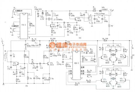
Figure (a) is the wireless transmission circuit; (b) is a wireless receiver circuit. (View)
View full Circuit Diagram | Comments | Reading(5843)
Remote control receiver decoder component TH9738
Published:2011/4/20 22:59:00 Author:Rebekka | Keyword: Remote control receiver, decoder component
View full Circuit Diagram | Comments | Reading(529)
Appliances infrared remote control receiver circuit diagram
Published:2011/4/20 22:31:00 Author:Rebekka | Keyword: Appliances , infrared remote control, receiver
View full Circuit Diagram | Comments | Reading(1289)
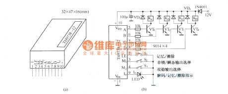
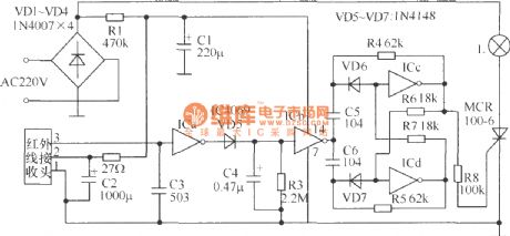
BA5201 (household appliances) infrared remote control decoding circuit diagram
Published:2011/4/22 4:29:00 Author:Rebekka | Keyword: household appliances, infrared remote control , decoding circuit
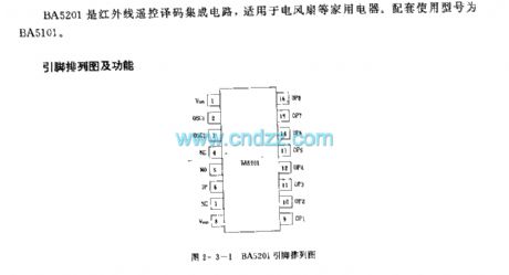
BA5201 is an infrared remote control decoding IC. It is suitable for electric fan and some other household appliances. The supporting use of it is BA5101.
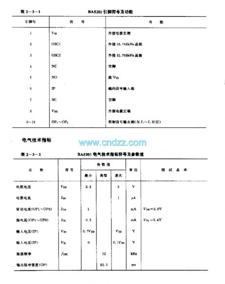
Here isthepinout and functions.
BA pin symbol and functions.
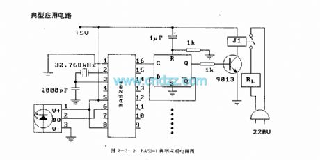
The typical application circuit.
(View)
View full Circuit Diagram | Comments | Reading(1994)
ACCORD combined meter circuit diagram
Published:2011/4/25 1:28:00 Author:Rebekka | Keyword: ACCORD, combined meter
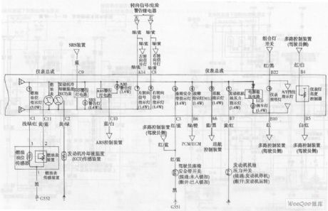
ACCORD combined meter circuit diagram is shown as above. (View)
View full Circuit Diagram | Comments | Reading(603)
ACCORD multiple control system circuit diagram
Published:2011/4/25 1:26:00 Author:Rebekka | Keyword: ACCORD, multiple control system
View full Circuit Diagram | Comments | Reading(565)
Accord Car navigation system circuit diagram
Published:2011/4/25 1:25:00 Author:Rebekka | Keyword: Accord car navigation system
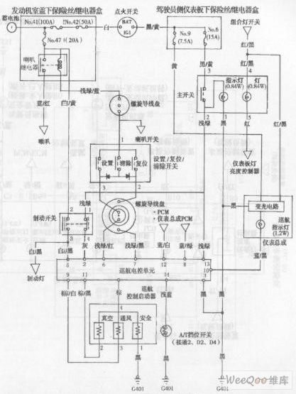
View full Circuit Diagram | Comments | Reading(1012)
ACCORD combined meter circuit diagram 1
Published:2011/4/25 1:29:00 Author:Rebekka | Keyword: ACCORD, combined meter
ACCORD combined meter circuit diagram is shown as above. (View)
View full Circuit Diagram | Comments | Reading(595)
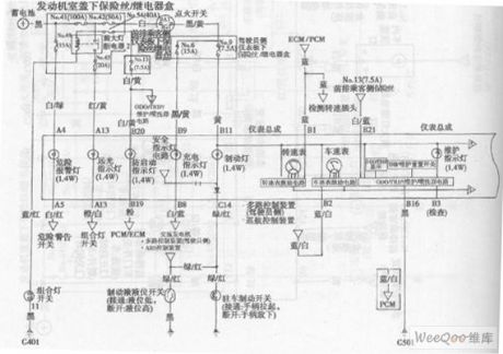
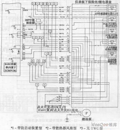
ACCORD 2003 models engine circuit diagram 6
Published:2011/4/25 1:36:00 Author:Rebekka | Keyword: ACCORD , 2003 models, engine
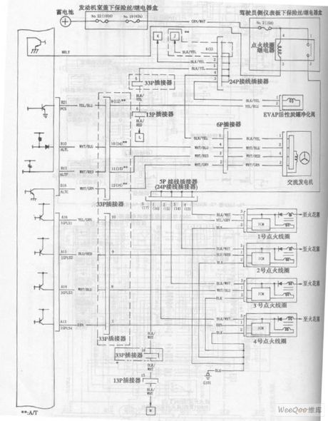
ACCORD 2003 models engine circuit diagram is shown as above. (View)
View full Circuit Diagram | Comments | Reading(542)
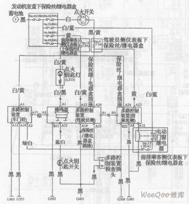
ACCORD anti-theft system circuit diagram 3
Published:2011/4/25 1:30:00 Author:Rebekka | Keyword: ACCORD , anti-theft system
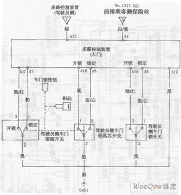
ACCORD anti-theft system circuit diagram is shown as above. (View)
View full Circuit Diagram | Comments | Reading(586)
ACCORD anti-theft system circuit diagram 1
Published:2011/4/25 1:31:00 Author:Rebekka | Keyword: ACCORD, anti-theft system
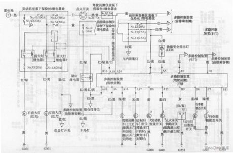
ACCORD anti-theft system circuit diagram is shown as above. (View)
View full Circuit Diagram | Comments | Reading(579)
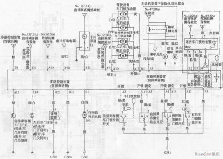
ACCORD anti-theft system circuit diagram 2
Published:2011/4/25 1:31:00 Author:Rebekka | Keyword: ACCORD , anti-theft system
View full Circuit Diagram | Comments | Reading(568)
ACCORD airbag system circuit diagram
Published:2011/4/25 1:32:00 Author:Rebekka | Keyword: ACCORD , airbag system
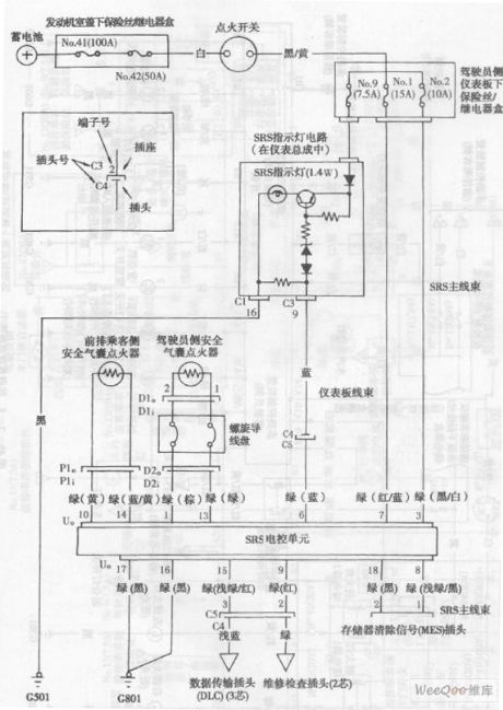
ACCORD airbag system circuit diagramis shown as above. (View)
View full Circuit Diagram | Comments | Reading(871)
ACCORD 2003 models engine circuit diagram 5
Published:2011/4/25 1:35:00 Author:Rebekka | Keyword: ACCORD , 2003 models , engine
ACCORD 2003 models engine circuit diagram is shown as above. (View)
View full Circuit Diagram | Comments | Reading(614)
| Pages:2014/2234 At 2020012002200320042005200620072008200920102011201220132014201520162017201820192020Under 20 |
Circuit Categories
power supply circuit
Amplifier Circuit
Basic Circuit
LED and Light Circuit
Sensor Circuit
Signal Processing
Electrical Equipment Circuit
Control Circuit
Remote Control Circuit
A/D-D/A Converter Circuit
Audio Circuit
Measuring and Test Circuit
Communication Circuit
Computer-Related Circuit
555 Circuit
Automotive Circuit
Repairing Circuit