
Circuit Diagram
Index 2000
Steady voltage circuit with adjustable output voltage
Published:2011/4/26 20:35:00 Author:Nicole | Keyword: steady voltage, adjustable output voltage
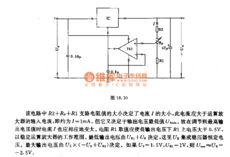
In this circuit, the current I is decided by R2+RP+R1 branch resisitance, the current should be higher than the input currrent of operational amplifier, that is I=1mA. It also depends on the mimimum output voltage UAmin. When the voltage is adjusted to the maximum value, the current I becomes higher too. The resistance R1 should ensure the voltage on R1 higher than 0.5V, to stabilize the work range of operational amplifier. The lowest output voltage is determined by UR1+UR, UR is the integrated regulator constant voltage. The highest output voltage is decided by UE*(-US+UR2). If US=1.5V, UR2=1V, then Umax≈UE=-2.5V. (View)
View full Circuit Diagram | Comments | Reading(611)
The Circuit Of Multi-Channel Demodulator Of CD4051 and CH3130
Published:2011/4/26 8:57:00 Author:TaoXi | Keyword: Multi-Channel Demodulator
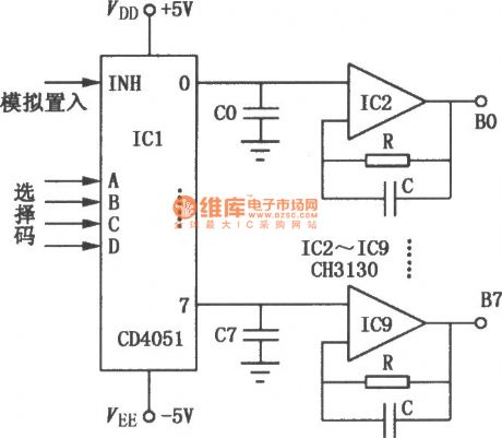
This circuit is composed of the (View)
View full Circuit Diagram | Comments | Reading(2574)
TDA8351 pin functions and data circuit
Published:2011/4/26 20:05:00 Author:TaoXi | Keyword: pin functions and data
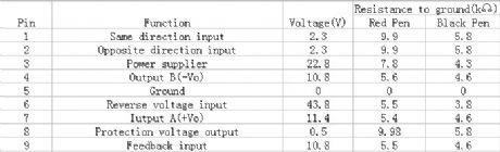
2.Pin functions and data circuit
The TDA8351 pin functions and data circuit is as shown in table 53.
Table 53. The TDA8351's pin functions and data
(View)
View full Circuit Diagram | Comments | Reading(2378)
Circuit Diagram of 555 Economy Fluorescent Display Filament Voltage Supplier
Published:2011/4/26 18:32:00 Author:Christina | Keyword: Economy, Fluorescent Display, Filament Voltage
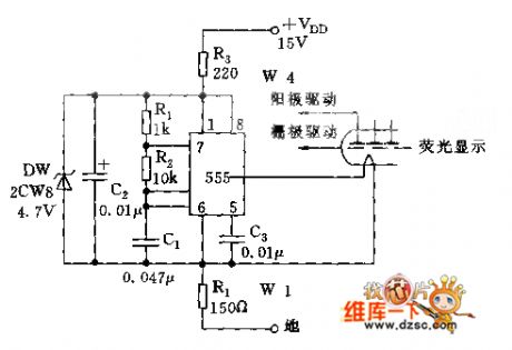
Most fluorescence filament code tubes of the calculator need to add the 6V DC and the several KHZ AC voltage (VP-P voltage), this circuit can meet the requirement.
As shown, 555 and R1, R2, C1form the astable-multivibrator, the oscillation frequency f=1.44/(R1+2R2), C1 is about 4KHZ. And the DC bias of the filament is VDD·R4/(R3+R4)≈6V.
Welcome to reprint, the information is from the Weiku Electronic Market Network (www.dzsc.com). (View)
View full Circuit Diagram | Comments | Reading(840)
Circuit Of On-off Function Remote Voltage Regulator
Published:2011/4/22 3:03:00 Author:Christina | Keyword: Remote, Voltage Regulator, On-off Function
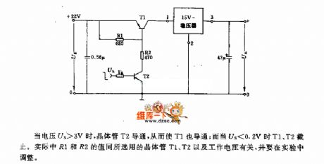
When voltage Us>3V, transistor T2 turns on, and T1 turns on too; but when the Us<0.2V, T1 and T2 turn off. Actually the value of R1 and R2 is related to transistor T1,T2 and operating voltage, you need to adjust the value inexperiment. (View)
View full Circuit Diagram | Comments | Reading(620)
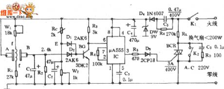
Anti-interfere voice control switch circuit
Published:2011/4/26 20:14:00 Author:TaoXi | Keyword: Anti-interfere, voice control switch
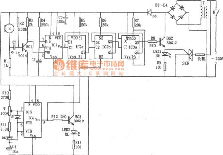
The anti-interfere voice control switch circuit is as shown:
(View)
View full Circuit Diagram | Comments | Reading(1071)
TC909OBN9 digital hang-shaped filter-type Y/C separation circuit
Published:2011/4/26 8:54:00 Author:TaoXi | Keyword: digital hang-shaped, filter-type Y/C separation
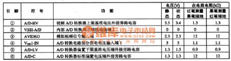
The TC909OBN9 is designed as one kind of digital hang-shaped filter-type Y/C separation circuit which is produced by the TOSHIBA company, and this device can be used in new large-screen color TV sets.
1.Features
The TC909OBN9 is composed of the video A/D converter, the D/A converter, the I2C bus interface circuit, the PLL VCO circuit and the Y/C separation circuit.
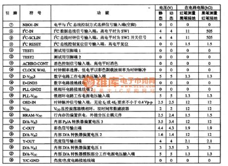
2.Pin functions and data
The TC9090BN is in 28-pin dual in-line package, the pin functions and data is as shown in table 1.
Tip: If the digital Y/C circuit failure, please check the RC components outside the TC909OBN(20)-pin.
Table 1. The pin functions and data of the TC9090BN (View)
View full Circuit Diagram | Comments | Reading(477)
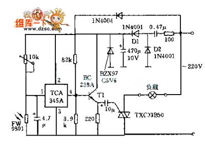
Long-Time Disconnect Delayer Circuit
Published:2011/4/22 4:26:00 Author:Christina | Keyword: Long-Time Disconnect, Delayer Circuit
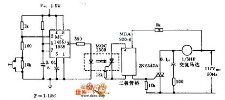
If we combine the timer 555, optical isolator 1300 and the bridge trigger triac switch, and press the control switch to supply power to the AC motor or other devices for 1h, timer(2)'s voltage will be less than 1/3Vcc, the timer output power become high, so the LED turn-on. At the same time, the capacitor of (7) starts charging, and before the voltage is 2/3VCC, output power is still high; when the output power back to low, turn off the motor.
(View)
View full Circuit Diagram | Comments | Reading(1595)
Frequency deviation measurement Circuit
Published:2011/4/26 18:37:00 Author:Christina | Keyword: Frequency deviation measurement
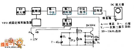
This circuit uses the same simple crystal oscillator and oscilloscope of carrier frequency deviation from center frequency with the fixed or adjustable FM receiver. The vertical amplifier of the oscilloscope uses the direct couple mode. To calibrate the tuned oscillator and display the figure higher than the receiver's second vibration 10KHZ or lower than the receiver's second vibration 15KHZ, we need to calibrate the oscilloscope screen. Because the transmitter's frequency is equal in the two channels, so we just need to adjust one oscilloscope.
(View)
View full Circuit Diagram | Comments | Reading(578)
Konka 60P Movement Rear Projection TV Failure Protection Circuit
Published:2011/4/26 18:38:00 Author:Christina | Keyword: Movement Rear Projection TV, Konka 60P, Failure Protection
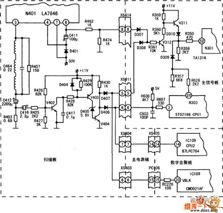
The Konka 60P Movement Rear Projection TV Failure Protection Circuit is as shown:
(View)
View full Circuit Diagram | Comments | Reading(645)
Hitachi NP8C Movement Power Supplier Circuit
Published:2011/4/24 21:12:00 Author:Christina | Keyword: Movement Power Supplier
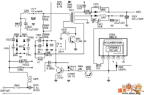
The Hitachi NP8C Movement Power Supplier Circuit is as shown:
(View)
View full Circuit Diagram | Comments | Reading(687)
High speed Rise-edge triggered switch circuit composed of MIC5158
Published:2011/4/26 20:08:00 Author:TaoXi | Keyword: High speed, Rise-edge triggered switch
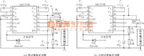
The high speed Rise-edge triggered switch circuit is as shown:
(View)
View full Circuit Diagram | Comments | Reading(543)
Low-cost thermal protection circuit diagram with adjustable temperature limit and programmable hysteresis voltage
Published:2011/4/26 4:09:00 Author:Rebekka | Keyword: adjustable temperature limit , programmable hysteresis voltage
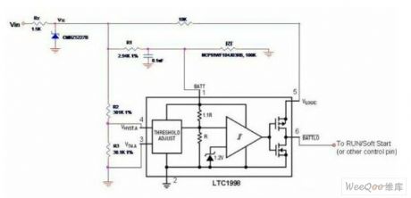
Thermal protection is very important in many power systems. Figure 1 shows a low-cost thermal protection circuit. LTC1998 is used for 6-pin battery monitoring SOT-23 package comparator. In this circuit it is used as heat protection. The thermal protection circuit can provide very useful features. Such as adjustable transition temperature, programmable hysteresis voltage and remote temperature sensing. When the detection point temperature rises. The voltage (Vbatt) of LTC1998 pin 1 will decline because of RT resistance. If Vbatt drops below 2.5V. The LTC1998 internal comparator transition changes, and Vbattlo (pin 6) turn to logic low. Pin 6 can be connected to the operation of the relevant power / soft-start (enable / shutdown) control side. Therefore, if the temperature rises to a pre-set trip point, you can turn off the power to prevent overheating.
(View)
View full Circuit Diagram | Comments | Reading(2161)
Circuit Of Remote Control Helicopter Driver Circuit
Published:2011/4/24 21:12:00 Author:Christina | Keyword: Remote Control Helicopter, Driver Circuit
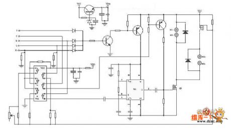
The Circuit Of Remote Control Helicopter Driver Circuit is as shwon:
(View)
View full Circuit Diagram | Comments | Reading(5998)
Nanosecond pulse detection circuit
Published:2011/4/26 18:42:00 Author:Christina | Keyword: Nanosecond pulse, detection
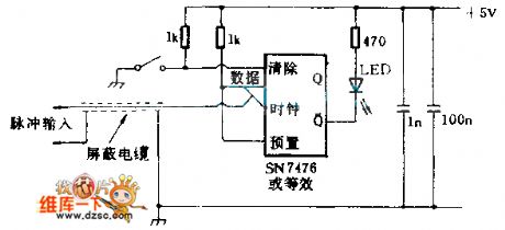
This circuit can detects the no-reproduce digital pulse of microsecond or nanosecond. The bistable IC sends the pulse information from the data input port to the Q output port, and this bistable IC uses the clock pulse along as the time base to stimulate the LED indicator.
(View)
View full Circuit Diagram | Comments | Reading(975)
Two-way SCR light control switch circuit
Published:2011/4/24 21:13:00 Author:Christina | Keyword: Two-way SCR, light control switch
The Two-way SCR light control switch circuit is as shwon:
(View)
View full Circuit Diagram | Comments | Reading(1650)
Squirrel Cage Motor Pole Changing And Speed Governing Wiring Circuit
Published:2011/4/26 5:14:00 Author:Robert | Keyword: Squirrel Cage, Motor, Pole Changing, Speed Governing, Wiring
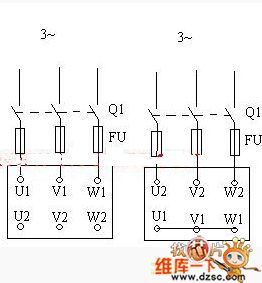
Squirrel Cage Motor Pole Changing And Speed Governing Wiring Circuit is shown above. (View)
View full Circuit Diagram | Comments | Reading(1365)
Ventilator Auto Exhauster Circuit (1)
Published:2011/4/26 5:16:00 Author:Robert | Keyword: Ventilator, Auto Exhauster
Ventilator Auto Exhauster Circuit (1) is shown below:
(View)
View full Circuit Diagram | Comments | Reading(725)
Squirrel Cage Wound-Rotor Asynchronous Motor Circuit
Published:2011/4/26 5:18:00 Author:Robert | Keyword: Squirrel Cage, Wound-Rotor, Asynchronous Motor
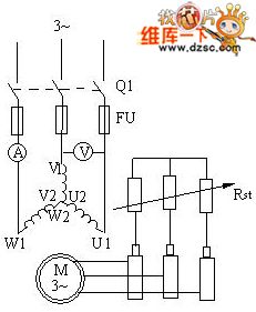
Squirrel Cage Wound-Rotor Asynchronous Motor Circuit is shown above. (View)
View full Circuit Diagram | Comments | Reading(1658)
Video Switching Circuit
Published:2011/4/26 5:48:00 Author:Robert | Keyword: Video, Switching
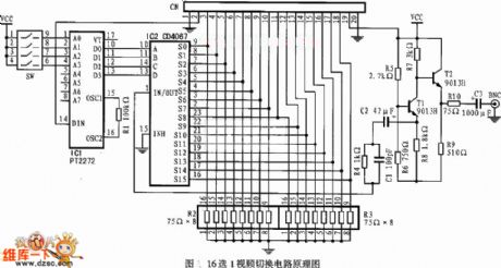
Video Switching Circuit is shown above. It is a16 points 1 video switching circuit. (View)
View full Circuit Diagram | Comments | Reading(820)
| Pages:2000/2234 At 2019811982198319841985198619871988198919901991199219931994199519961997199819992000Under 20 |
Circuit Categories
power supply circuit
Amplifier Circuit
Basic Circuit
LED and Light Circuit
Sensor Circuit
Signal Processing
Electrical Equipment Circuit
Control Circuit
Remote Control Circuit
A/D-D/A Converter Circuit
Audio Circuit
Measuring and Test Circuit
Communication Circuit
Computer-Related Circuit
555 Circuit
Automotive Circuit
Repairing Circuit