
Circuit Diagram
Index 1994
The pin functions and data circuit of the TDA8174
Published:2011/4/27 5:22:00 Author:TaoXi | Keyword: pin functions, data circuit

2. Pin functions
The pin-5 function and data circuit of the TDA8174 is as shown in table 46. Themaximum output current is 1.8A, and the maximum output power is 9W.
Table 46 The pin functions and data circuit of the TDA8174
(View)
View full Circuit Diagram | Comments | Reading(696)
Pin functions and data of the TDA8175
Published:2011/4/27 4:58:00 Author:TaoXi | Keyword: Pin functions, data

2. Pin functions and data
The pin-5 function and data circuit of the TDA8175 is as shown in table 47. The TDA8175 is in the 7-pin single in-line package.
Table 47 The pin functions and data circuit of the TDA8175
(View)
View full Circuit Diagram | Comments | Reading(497)
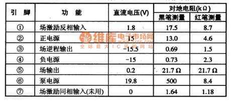
The pin functions and data of the integrated circuit
Published:2011/4/27 4:53:00 Author:TaoXi | Keyword: pin functions, data

TDA8177 -- field-scanning output circuit
The TDA8177 is designed as one kind of new field scanning output integrated circuit which is produced by the Philips company, and this device can be used in some kinds of large screen color TV.
1.Features
The TDA8177 is composed of the Field-excitation signal-amplification circuit, the field output power amplifier, the field back-pulse generator circuit, the field-scanning pump power supply circuit and other circuits.
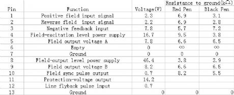
2.Pin functions and data
The TDA8177 is in the 7 pins single in-line plastic package, the pin functions and data is as shown in table 48, and the measured data is displayed in Sony Westlake CD2999T large screen color TV.
Table 48 Pin functions and data of the TDA8177
(View)
View full Circuit Diagram | Comments | Reading(631)
TC9OA49D digital comb filter Y/C separate circuit
Published:2011/4/27 10:01:00 Author:TaoXi | Keyword: digital, comb filter, Y/C separate
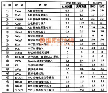
The TC9OA49D is designed as one kind of digital comb filter Y/C separate circuit which is produced by the TOSHIBA company, and this device can be used in domestic and imported new large-screen color TV.
The TC9OA49D is in 20-pin dual in-line package, the pin functions and data is shown in table 1. The data is from the Haier Baodelong large screen color TV.
Table 1 The pin functions and data of TC9OA49D (View)
View full Circuit Diagram | Comments | Reading(528)
555 Digital temperature sensor header circuit
Published:2011/4/27 4:26:00 Author:Ecco | Keyword: 555 , Digital, temperature, sensor header
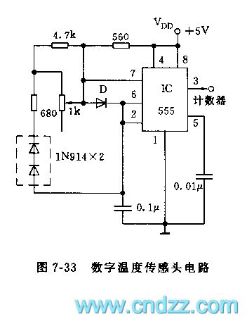
As shown in Figure 7-33, the sensor header consists of two 1N914 diodes and a multivibrator composed of 555 and other components. Diode D is used as a part of discharging loop of 555 oscillator, the oscillation frequency changes proportionally with temperature and the impedance of the diode. The oscillation pulse output by 555 and then sent to the frequency counter to count, to reflect the changes of temperature.
(View)
View full Circuit Diagram | Comments | Reading(1763)
Metal detector 4
Published:2011/4/26 4:48:00 Author:Ecco | Keyword: Metal detector
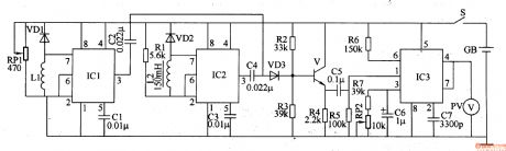
The working principle.The metal detector circuit consists of detection oscillator, reference oscillator, mixer and signal display, it is shown as Figure 8-70.
The detection oscillator circuit is composed of the time base oscillator ICl, inductor Ll, potentiometer RPl, diode VDl and capacitors Cl, C2. Reference oscillator (reference oscillator) circuit is composed of the time-base integrated circuit IC2, inductor L2, diode VD2, resistor Rl and capacitors C3, C4. Mixer is composed of the transistor V, diode VD3 and resistors R2-R4. Signal display circuit consists of integrated circuit IC3, voltage meter RC PV and peripheral components.
Rl-R7 choose 1/4W or 1/8W carbon film resistors. RPl uses synthetic membranes potentiometer with switch; RP2 uses synthetic membrane potentiometer without switch or variable resistor. Cl-C5, C7 use ceramic capacitors; C6 uses the aluminum electrolytic capacitor with the voltage being greater than lOV. VDl-VD3 use 2AP9, 2APlO common germanium germanium diode or 2AK series switching diode. V uses 3DG6 or S9018 silicon NPN transistor.
(View)
View full Circuit Diagram | Comments | Reading(11553)
Pin functions and data circuit of the TDA8350Q
Published:2011/4/27 4:33:00 Author:TaoXi | Keyword: Pin functions, data circuit
2. Pin functions and data
The pin functions and data circuit of the TDA8350Q is as shown in table 52.
Table 52 The pin functions and data circuit of the TDA8350Q
(View)
View full Circuit Diagram | Comments | Reading(3674)
Shanghai GM BUICK commercial vehicle(GL8) remote control door lock circuit diagram
Published:2011/4/27 4:24:00 Author:Nicole | Keyword: Shanghai GM BUICK, commercial vehicle, remote control door lock
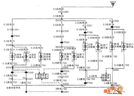
View full Circuit Diagram | Comments | Reading(817)
555 Audio ohmmeter circuit
Published:2011/4/27 4:16:00 Author:Ecco | Keyword: 555 , Audio , ohmmeter
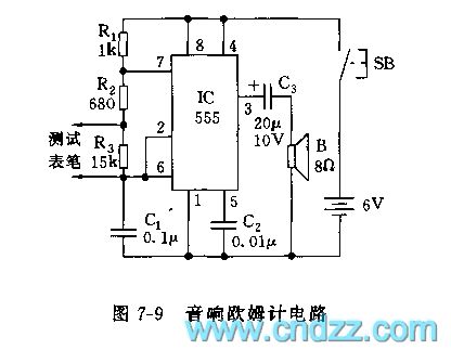
As shown in Figure 7-9, audio ohmmeter uses 555 as the core. The circuit is actually a multivibrator. The table pen is connected to resistor Rx, and then connected to R3 in parallel, the resistance is different, the oscillation frequency is different, the level of speaker sound is also different. The resistance of measured resistor can be estimated by the level of sound.
(View)
View full Circuit Diagram | Comments | Reading(1562)
The pin functions and data circuit of TDA81795
Published:2011/4/27 4:15:00 Author:TaoXi | Keyword: pin functions, data circuit
TDA8179S -- field-scanning roll-out carry-on circuit
The TDA8179S is designed as one kind of new field scanning output integrated circuit which is produced by the Philips company, and this device can be used in domestic and imported brands of large screen color TV.
1.Features
The TDA8179S is composed of the field-excitation signal-amplification circuit, the field output power amplifier, the field back-pulse generator circuit, the field-scanning pump power supply circuit and other circuits.
2.Pin functions and data
The TDA8179S is in the 7 pins single in-line plastic package, the pin functions and data is as shown in table 51, and the measured data is displayed in Sony KV-S34MHl large screen color TV.
Table 51 Pin functions and data of the TDA8179S
(View)
View full Circuit Diagram | Comments | Reading(625)
Shanghai GM BUICK commercial vehicle(GL8) anti-theft system circuit diagram
Published:2011/4/27 4:08:00 Author:Nicole | Keyword: Shanghai GM BUICK, commercial vehicle, anti-theft system
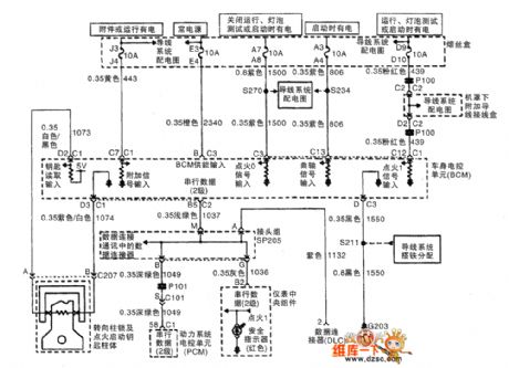
View full Circuit Diagram | Comments | Reading(538)
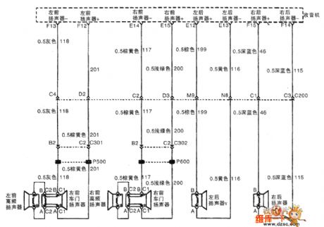
Shanghai GM BUICK commercial vehicle(GL8) audio system loudspeaker system RPOUQ3 circuit diagram
Published:2011/4/27 4:17:00 Author:Nicole | Keyword: Shanghai GM BUICK, commercial vehicle, audio system, loudspeaker system
View full Circuit Diagram | Comments | Reading(428)
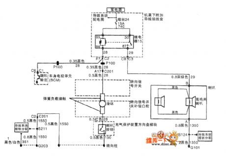
Shanghai GM BUICK commercial vehicle(GL8) horn circuit diagram
Published:2011/4/27 4:09:00 Author:Nicole | Keyword: Shanghai GM BUICK, commercial vehicle, horn
View full Circuit Diagram | Comments | Reading(761)
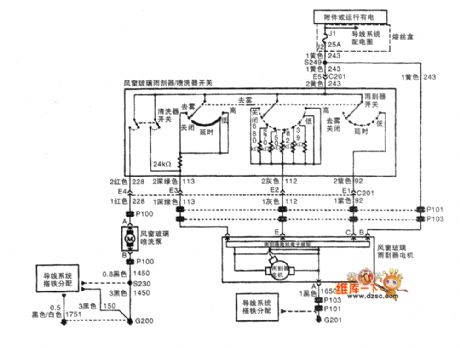
Shanghai GM BUICK commercial vehicle(GL8) wiper/washing system circuit diagram
Published:2011/4/27 4:11:00 Author:Nicole | Keyword: Shanghai GM BUICK, commercial vehicle, wiper system, washing system
View full Circuit Diagram | Comments | Reading(666)
Electronic hypnotic device 5
Published:2011/4/26 6:15:00 Author:Ecco | Keyword: Electronic , hypnotic device
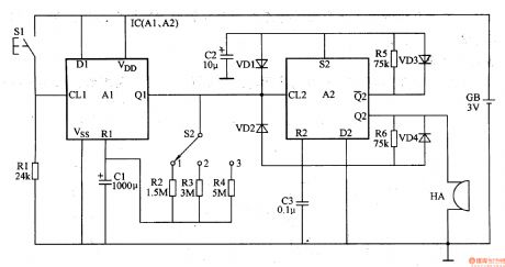
The working principle.
The electronic hypnotic device is composed of monostable circuit, self-excited multivibrator circuit and buzzer HA and other components, it is shown in Figure 9-142.
Monostable circuit is composed of dual D flip-flop integrated circuit IC (Al, A2) and resistors Rl-R4, capacitor Cl, control button 51 and delay time selection switch 52. Self-excited multivibrator circuit is composed of the other D flip-flop A2 inside the IC and diodes VDl-VD4, resistors R5, R6, capacitors C2, C3. Pressing button S1, the flip is triggered by the monostable circuit, IC's Ql outputs high level, the multi-harmonic oscillator works, the Q2 of IC outputs 2Hz oscillation frequency signal, the driver HA issues a similar sound of raindrops to help people sleep. When the charging of Cl is over, one-shot circuit returns to steady state, IC's Ql outputs low level again, multi-harmonic oscillator stops working, HA stops the sound. (View)
View full Circuit Diagram | Comments | Reading(1402)
AC timer switch control circuit composed of μA7555
Published:2011/4/27 4:00:00 Author:TaoXi | Keyword: AC, timer switch control
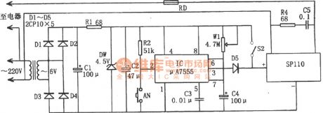
The AC timer switch control circuit is as shown:
(View)
View full Circuit Diagram | Comments | Reading(603)
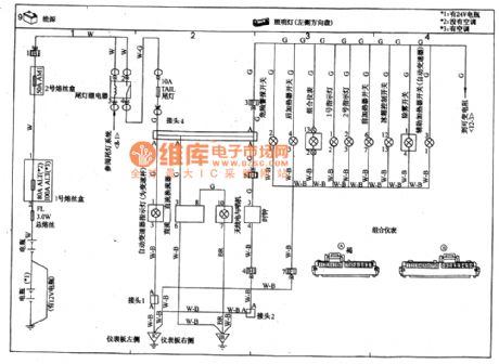
TOYOTA COASTER coach illuminator(left hand steering) circuit wiring circuit diagram
Published:2011/4/27 3:57:00 Author:Nicole | Keyword: TOYOTA COASTER, coach, illuminator
View full Circuit Diagram | Comments | Reading(1016)
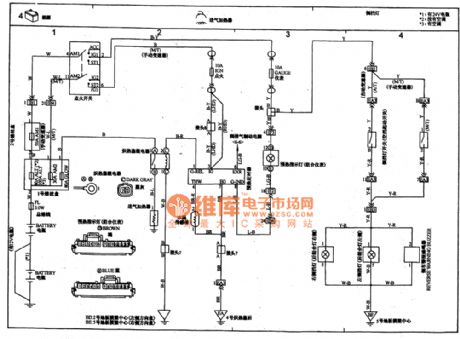
TOYOTA COASTER coach air intake heater, reversing light circuit wiring circuit diagram
Published:2011/4/27 3:59:00 Author:Nicole | Keyword: TOYOTA COASTER, coach, air intake heater, reversing light
View full Circuit Diagram | Comments | Reading(1636)
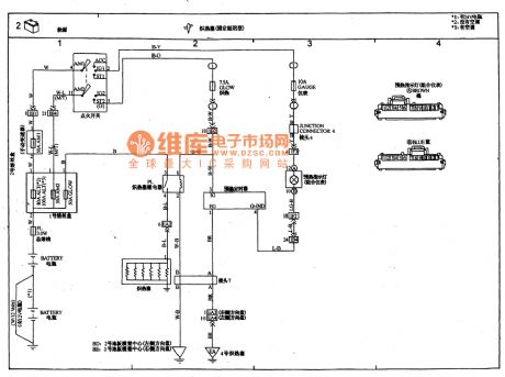
TOYOTA COASTER coach glow plug(fixed delay type) circuit wiring circuit diagram
Published:2011/4/27 4:01:00 Author:Nicole | Keyword: TOYOTA COASTER, coach, glow plug
View full Circuit Diagram | Comments | Reading(1993)
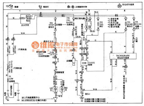
TOYOTA COASTER coach control lamp, cigar lighter, clock, automatical speedometer circuit wiring circuit diagram
Published:2011/4/27 3:53:00 Author:Nicole | Keyword: TOYOTA COASTER, coach, control lamp, cigar lighter, clock, speedometer
View full Circuit Diagram | Comments | Reading(1837)
| Pages:1994/2234 At 2019811982198319841985198619871988198919901991199219931994199519961997199819992000Under 20 |
Circuit Categories
power supply circuit
Amplifier Circuit
Basic Circuit
LED and Light Circuit
Sensor Circuit
Signal Processing
Electrical Equipment Circuit
Control Circuit
Remote Control Circuit
A/D-D/A Converter Circuit
Audio Circuit
Measuring and Test Circuit
Communication Circuit
Computer-Related Circuit
555 Circuit
Automotive Circuit
Repairing Circuit