
Circuit Diagram
Index 1993
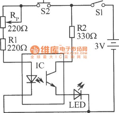
Simple detection circuit diagram of optocoupler
Published:2011/4/27 21:44:00 Author:Ecco | Keyword: Simple, detection , optocoupler
View full Circuit Diagram | Comments | Reading(1917)
The structure indicating diagram of rectangular chip resistor
Published:2011/4/27 21:42:00 Author:Ecco | Keyword: structure indicating , rectangular chip , resistor
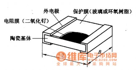
Structure and dimensionsRectangular chip resistors have two types, namely, thick film chip resistors and thin film chip resistors. The thick-film chip resistors are commonly used. The structure of rectangular chip resistors is shown as the chart.
(View)
View full Circuit Diagram | Comments | Reading(689)
PCA84C840P-054 Single-chip microcomputer integrated circuit diagram
Published:2011/4/27 21:38:00 Author:Ecco | Keyword: Single-chip , microcomputer, integrated circuit
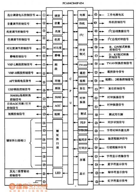

PCA84C840P-054 is a single-chip microcomputer integrated circuit manufactured by Philips, it is widely used in domestic and imported large screen color television with Philips machine assembly. PCA84C840P-054 IC uses 42-foot double row style package, the internal circuit block diagram and pin functions and signal flowing are shown as the chart, the pin code and data is listed in the table.
(View)
View full Circuit Diagram | Comments | Reading(956)
Digital engine tachometer circuit
Published:2011/4/27 21:11:00 Author:Christina | Keyword: Digital, engine tachometer

The tachometer shows the engine's crankshaft speed. The digital engine tachometer circuit is as the figure shown, this tachometer has a input signal conditioner (composed of u1 and u2-a), a pulse counter us, display drivers u4 and u5 drive two electronic display devices disp1 and disp2, a main clock u6 and a power regulator u7. Input signal is from the pulse signal of the engine ignition system distributor's breaker contact-point, this output signal is the circuit-trig signal. +5V power is supplied by the regulator u7, power of u7 is supplied by the 12v car power supply. The tachometer shows the two significant figures of the engine speed.
(View)
View full Circuit Diagram | Comments | Reading(2977)
400Hz signal source circuit
Published:2011/4/27 21:16:00 Author:Christina | Keyword: 400Hz, signal source

The 400Hz signal source circuit is as shown:
(View)
View full Circuit Diagram | Comments | Reading(556)
Photoelectric alarm circuit diagram
Published:2011/4/19 22:33:00 Author:Rebekka | Keyword: Photoelectric alarm
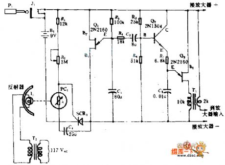
When light beam I1 and photocell between the PC1 are truncated, they will start the alarm circuit resulting in a special scanning a single audio signal. This signal is sent to a simple amplifier with amplified speakers. It will make an alarm signal. When the light I1 is truncated, PC1 resistance will become larger, SCR1 will be turned on, so that the negative power supply terminal B1 and the circuit in the back of SCR1 can be connected. Q1, Q3 are two single-junction transistor. They are used as oscillator components in the circuit. R3, C1 determine the oscillation frequency of Q1; R3, C3 determine the oscillation frequency of Q3; Q2 for amplification. The light and the photocell of the circuit can be placed on the door or window of the opposite sides of the mirror to collect light in the room.
(View)
View full Circuit Diagram | Comments | Reading(1130)
Low frequency Wien bridge sine wave oscillator(MC1456、μA741)
Published:2011/4/22 1:49:00 Author:Ecco | Keyword: Low frequency, Wien bridge, sine wave oscillator
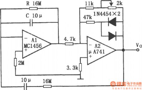
Figure shows the low frequency Wien bridge sine wave oscillator circuit. The circuit uses the exponential characteristics of the diode to stabilize 0.001Hz sine wave generator amplitude, so as not to cause a larger time constant, because the diodes can quickly change their equivalent dynamic resistance. This stability is similar to the limiter. The 47kΩ resistor connecting to the diode in series is used to reduce the limiting effect of the diode, and can prevent the circuit distortion. In general Wien bridge oscillator, because of the limited input impedance of op amp, the R in the parallel RC can not be too high, so the oscillation frequency can not be too low. There are two op amps in the cirucit, RC is connected between the inverting input and output ens of op amp A1 and can increase the operational amplifier input impedance, so you can use a R with large resistance. The connection couldn't use FET input operational amplifier. (View)
View full Circuit Diagram | Comments | Reading(1723)
Low power Wien bridge oscillator composed of MC1454
Published:2011/4/21 6:07:00 Author:Ecco | Keyword: Low power , Wien bridge , oscillator

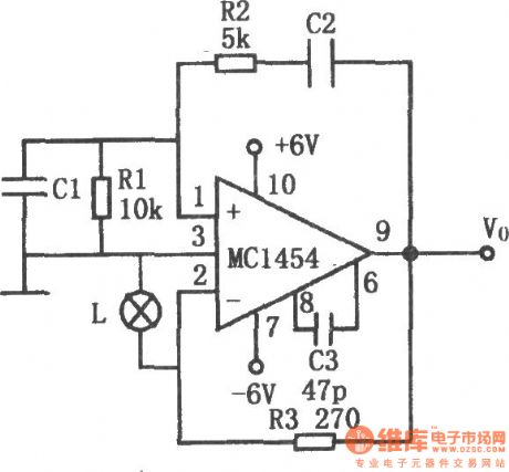
The chart shows the low power Wien bridge oscillator circuit. The circuit is characterized by little distortion when driving low impedance load and large capacitive loads. Operational amplifier used in the circuit could drive 8 ~ 10Ω load, the 10Ω load can provide 2 ~ 4V peak output voltage and the frequency is from 1Hz to 100kHz, distortion is less than 0.5%. Automatic gain control is achieved by a lamp L as the resistance of the bulb changing with the output voltage. Resistor R3 forms a negative feedback loop to determine the output signal amplitude. Capacitors C1 and C2, resistors R1 and R2 constitute a positive feedback. If the value of resistor R1 and the input impedance of the amplifier is equal, R2 = R1 / 2, C1 = C2, then the oscillation frequency; f0 = 1/2π,R1C1C3 is the high-frequency compensation capacitor. The following table lists the relationship between frequency and capacitance C1 (C2) .
(View)
View full Circuit Diagram | Comments | Reading(1217)
1488kHz signal generator and divider
Published:2011/4/21 6:22:00 Author:Ecco | Keyword: 1488kHz, signal generator, divider
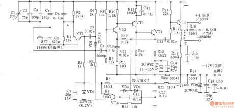
1488kHz master oscillator uses quartz crystal resonator stabilize frequency, the output is divided by the divider, then it gets three different square wave signal output in 4kHz, 12kHz, 124kHz. The circuit is shown as the chart. Transistors VTl, VT2, VT4, VT6: 3DG6C, β = 50 ~ 85, VT3: 3CG3D, β = 50 ~ 85, VT5: 3DGl308, β = 65 ~ 115. Variable devices T: using tank-shaped ferrite, model is MTT22F. Ll-2 uses Φ0.35mm high-strength wire with 36 turns. L3-4 uses Φ0.31mm high-strength wire with 21 turns. Al ~ A9: The D-type SG8228 CMOS, flip-flop, each integrated circuit has two D flip-flop components. Al0, All: 5G8058 gate integrated circuit, each circuit has two door components. Other components is shown as the figure, there is no special requirements.
(View)
View full Circuit Diagram | Comments | Reading(763)
Electronic smooth wheezing device
Published:2011/4/26 21:54:00 Author:Ecco | Keyword: Electronic , smooth wheezing device
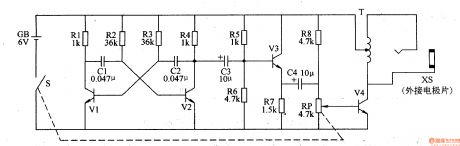
This example describes an electronic smooth wheezing device which is made by discrete electronic components, it produces high-voltage stimulation pulse, which can play the role of adjuvant therapy for cough patient. The working principleThe electronic smooth wheezing device circuit is composed of self-excited multivibrator, the buffer amplifier and voltage generator circuit, it is shown as Figure 9-156.
Self-excited multivibrator is composed of the transistor Vl, V2, capacitors Cl, C2 and resistors Rl-R4 and so on. Buffer amplifier circuit is composed of the emitter amplification tube V3, bias resistor R6 and geese coupling capacitors C3, C4. High-voltage generating circuit is composed of the potentiometer RP, resistors R8, amplified output tube V4, the garnet-type step-up transformer T and output socket XS. Self-excited multivibrator can generate the oscillation signal with frequency in 5OOHz, and it is amplified by the V3, V4 and transformer T, the outlet XS outputs pulse voltage which is more than lOOV.
Rl-R8 select 1/4W carbon film resistors or metal film resistors. RP selects WH-l5 series or WTR series of small synthetic carbon with switch potentiometer. Cl and C2 choose polyester capacitors or monolithic capacitors; C3 and C4 select the electrolytic capacitors with voltage value being greater than lOV. Vl-V3 use 3DG6 or S9014 silicon NPN transistor; V4 chooses S805O or C8050, 3DGl2 and other silicon NPN transistor. (View)
View full Circuit Diagram | Comments | Reading(998)
Motor protector 10
Published:2011/4/27 20:49:00 Author:Ecco | Keyword: Motor protector
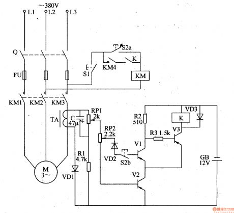
The motor protector described in the example can cut off the power supply when any phase of power in three-phase AC motor being lacking, it can prevent winding overheating damage due to broken phase operation.
The working principle
The motor protector circuit is composed of the voltage detection circuit and protection controlling execution circuit, it is shown as Figure 8-46.
Starting control circuit is composed of stopping button Sl, starting button S2 and AC contactor KM (the original motor starting circuit).
Voltage detection circuit is composed of the diodes VDl-VD3, Zener diode VSl-VS3, resistors Rl-R6, capacitors Cl-C3 and optocouplers VLCl-VLC3.
Protection control circuit consists of transistors V, relay K, the diode VD4 and resistor R7.
Rl, R3 and R5 use 1-2W metal film resistors; R8, R4, R6 and R7 use 1/4W carbon film resistors or metal film resistors.
Cl-C3 select aluminum electrolytic capacitors with voltage in 16V.
VDl-VD4 use 1N4007 silicon rectifier diodes.
VSl-VS3 select lW, 9 · IV silicon voltage regulator diodes.
V uses S8050, 3DG805O, BC136 or other models NPN silicon transistors.
VLCl-VLC3 use 4N25 or MCT2E, TL206 coupler.
K uses 9V DC relay. (View)
View full Circuit Diagram | Comments | Reading(2085)
Six-way each reset type touch switch circuit
Published:2011/4/27 20:43:00 Author:Nicole | Keyword: touch switch
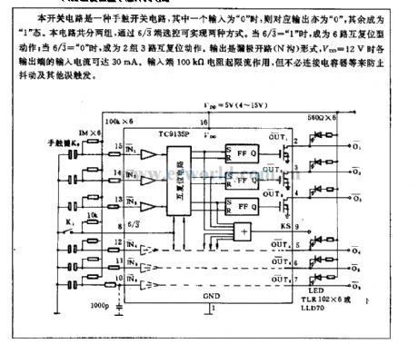
This switch circuit is a touch switch circuit, if one of inputs is 0 , then the corresponding output is 0 , the others are 1 . This circuit has two groups, the selection control can achieve two ways by 6/3 terminal. When 6/3= 1 , it will become six-way each reset type action; when 6/3= 0 , it will become two groups three-way each reset type action. The output is open drain(N ditch)type, when VDD=12V, the input current of all kinds output terminal can reach 30mA. Input terminal 100kΩ current takes the action of limiting current, but it is no need to connect capacitance to prevent wobble and other error trigger. (View)
View full Circuit Diagram | Comments | Reading(1001)
The pin functions and data circuit of the TDA8177F
Published:2011/4/27 4:44:00 Author:TaoXi | Keyword: pin functions, data
2. Pin functions and data
The pin functions and data circuit of theTDA8177F is as shown in table 52.
Table 49 The pin functions and data circuit of the TDA8177F
(View)
View full Circuit Diagram | Comments | Reading(531)
TDA9332H integrated block internal box circuit
Published:2011/4/27 8:45:00 Author:TaoXi | Keyword: integrated block, internal box
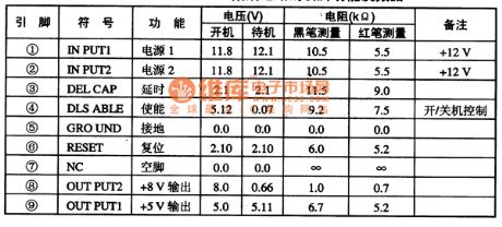
TDA8133--Dual polarity voltage regulator circuit
The TDA8133 is designed as one kind of dual polarity voltage regulator circuit which is produced by the PHILIPS company, and it can be used in Konka K/N series TV.
1.Features
The TDA8133 is composed of the power supply voltage regulator, standby control circuit, reset circuit, delay circuit and other circuits.
2.Pin functions and data
The TDA8133 is in the 9-pin single in-line package, the pin functions and data is as shown in table 43. This data is from the Konka T2168K color TV.
Table 43 The pin functions and data of the TDA8133
(View)
View full Circuit Diagram | Comments | Reading(1182)
TDA9210 integrated block internal box circuit
Published:2011/4/27 9:39:00 Author:TaoXi | Keyword: integrated block, internal box circuit
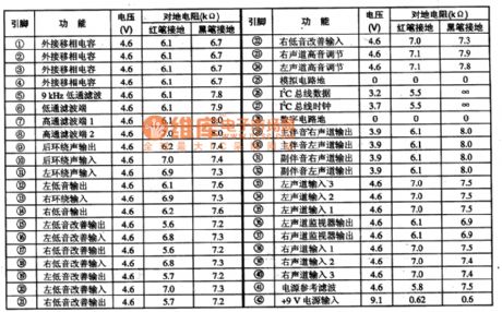
2.Pin functions and data
The TDA7429S is in the 42-pin double-row package, the power supply voltage is 9V, and it can be used in Changhong rear projection TV, the pin functions and data is as shown in table 40.
Table 40 The pin functions and data of the TDA7429S
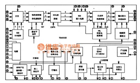
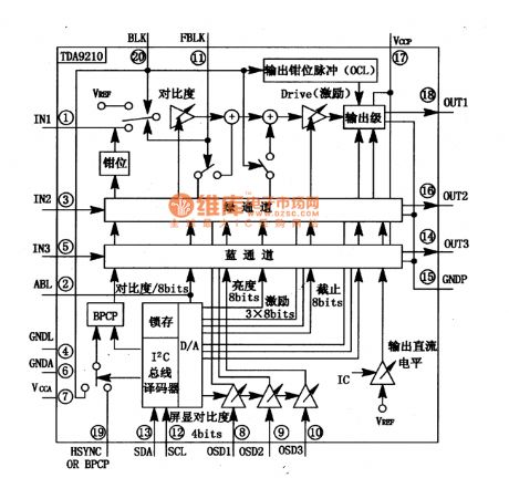
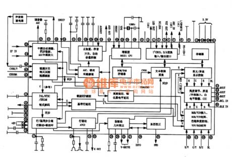
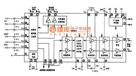
TDA9210--Charge with a video processing integrated circuit
The TDA9210 is designed as one kind of 15OMHz bandwidth video signal processing integrated circuit which is produced by the PHILIPS company with I(2)C bus control technology, and this device can be used with the TDA95XX series in applications of SVGAl7-21-inch color monitor.
1.Features
The TDA9210 has the R, G, B video signal amplifier, the OSD (on screen display) processor, OSD contrast control circuit, the brightness control circuit, contrast control circuit, the tube cut-off point (dark balance) adjust circuit, tube excitation control (light balance adjust) circuit, CRT beam-current limite circuit and the I(2)C bus decoder, the latcher, the D/A convert circuit.etc. The integrated block's internal circuit is as shown in figure 40.
(View)
View full Circuit Diagram | Comments | Reading(685)
Miniaturized Isolation Amplifier Circuit
Published:2011/4/26 0:01:00 Author:Joyce | Keyword: Miniaturized, Isolation Amplifier
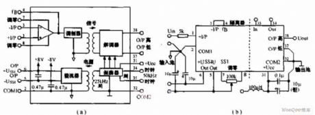
Miniaturized isolation amplifier ISO212P is a transformer coupling isolation amplifier,as simplified schematic diagram is shown in figure (a),and zero setting methods in figure (b).
Features: 12-degree precision; Miniaturization with theheight lower than 12mm; Standardized pipe spacing of 2.54 mm; Capabilityof providing 8V / 5 isolation power source to external ; Ability to adjust input disorders ; Low power consumption of 75mW; Operation with single power supply of 10 ~ 15V.
Application: channel segregation of sensor in industrial process control ; isolation for 4 ~ 20mA signal circuit ; Motor and SCR circuit;isolation for data detection/test equipment ; communication isolation and multi-channel transmission system. (View)
View full Circuit Diagram | Comments | Reading(680)
Constant current source using integrated regulator circuit
Published:2011/4/26 3:12:00 Author:May | Keyword: Constant current source, integrated regulator circuit
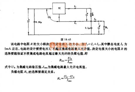
The value of resistor R in this circuit can determine the value of constant current I3. But I3=I1+I2, among them, quiescent current I2 is about 5mA. The design of circuit must make the voltage U not higher than the maximum value of integrated circuit. The selection of resistor R should make sure that the integrated circuit current not higher than maximum load value, namely, Rmin=UR/IMAXIn the formaula, UR is integrated circuit constanst voltage ,IMAX is integrated maximum current value.Load resistor RL must satisfy the following relation:RL=(UE-UR)/IMAX (View)
View full Circuit Diagram | Comments | Reading(890)
TDA9302H integrated block internal box circuit
Published:2011/4/27 9:06:00 Author:TaoXi | Keyword: integrated block, internal box
TDA7481--Left and right Lu-channel audio power amplifier circuit
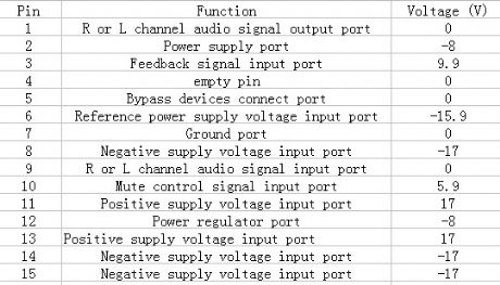
The TDA7481 is designed as one kind of left and right Lu-channel audio power amplifier circuit which is produced by the PHILIPS company, and it can be used in large screen color TV, hi-fi and other systems.
1.Features
The TDA7481 is composed of two power amplifier circuits, mute control circuit, reference voltage regulator circuit and other circuits.
2.Pin functions and data
The TDA7481 is in the 15-pin single in-line DIP package, the pin functions and data is as shown in table 42. This data is from the Konka T2168K color TV.
Table 42 The pin functions and data of the TDA7481
3.Internal box circuit
The TDA9302H integrated block internal box circuit is as shown in figure 42.
(View)
View full Circuit Diagram | Comments | Reading(1014)
TDA9380 integrated block internal box circuit
Published:2011/4/27 5:50:00 Author:TaoXi | Keyword: integrated block, internal box
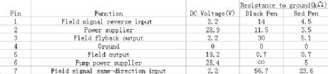
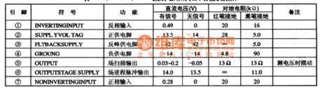
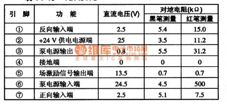
TDA8170 -- field-scanning output circuit
TheTDA8170 is designed as one kind of new field scanning output integrated circuit which is produced by the Philips company, and this device can be used in some kinds of large screen color TV.
1.Features
The TDA8170 is composed of the field pre-amplifier circuit, the field output power amplifier, the field back-pulse generator circuit, the field-scanning pump power supply circuit and other circuits.
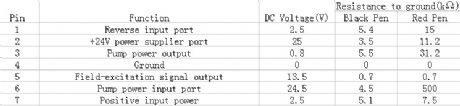
2.Pin functions and data
The TDA8170 is in the 7 pins single in-line plastic package, the pin functions and data is as shown in table 44, and the measured data is from the Sony KV-3400DY2 color TV.
Table 44 Pin functions and data of the TDA8170
(View)
View full Circuit Diagram | Comments | Reading(1903)
TDA9860 integrated block internal box circuit
Published:2011/4/27 5:41:00 Author:TaoXi | Keyword: integrated block, internal box circuit
2. Pin functions and data
The pin functions and data circuit of the DTA8172 is as shown in table 45. The DTA8172 is in the 7-pin single in-line package.
Table 45 The pin functions and data circuit of the DTA8172
(View)
View full Circuit Diagram | Comments | Reading(2025)
| Pages:1993/2234 At 2019811982198319841985198619871988198919901991199219931994199519961997199819992000Under 20 |
Circuit Categories
power supply circuit
Amplifier Circuit
Basic Circuit
LED and Light Circuit
Sensor Circuit
Signal Processing
Electrical Equipment Circuit
Control Circuit
Remote Control Circuit
A/D-D/A Converter Circuit
Audio Circuit
Measuring and Test Circuit
Communication Circuit
Computer-Related Circuit
555 Circuit
Automotive Circuit
Repairing Circuit