
Circuit Diagram
Index 1982
Analog temperature controller circuit diagram
Published:2011/4/28 22:22:00 Author:Ecco | Keyword: Analog, temperature controller
View full Circuit Diagram | Comments | Reading(1207)
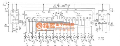
Analog turning disc guessing award device circuit diagram
Published:2011/4/28 21:39:00 Author:Ecco | Keyword: Analog, turning disc , guessing award device
View full Circuit Diagram | Comments | Reading(627)
Playing football game circuit diagram
Published:2011/4/28 22:18:00 Author:Ecco | Keyword: Playing football game
View full Circuit Diagram | Comments | Reading(1455)
Cursor control circuit
Published:2011/4/27 9:45:00 Author:Nicole | Keyword: cursor control circuit
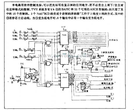
This circuit uses software to control cursor, then the cursor can be writen at any place of display screen, it is not limited by the form of from above to below or from left to right. TVII system contains 8K bits BASIC and 32 usable ASCII control codes, but only 18 codes are used. Three 7445 BCD code changes into BCD decoder work as the way of 3 lines change into 8 lines, the (12) is used as chip start-up line. When the (12) is low level, there must be a output turning into low level. (View)
View full Circuit Diagram | Comments | Reading(697)
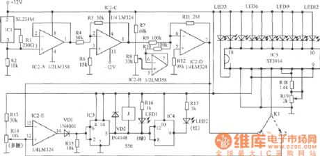
Acousto-optic control stair delay switch circuit with operational amplifier
Published:2011/4/28 4:33:00 Author:Nicole | Keyword: acousto-optic control, stair delay switch, operational amplifier
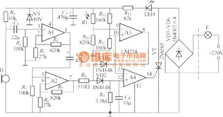
The figure is as shown, it is a acousto-optic control stair delay switch which adopts LM324 operational amplifier, it adopts two-wire system connection, it can replace the ordinary light switch directly, it is not needed to change the indoor original wiring. In figure, the operational amplifier A1~A4 which is connected into four voltage comparator can use a single power supply four operational amplifier IC LM324, theother components are as shown, there is no special requirements. (View)
View full Circuit Diagram | Comments | Reading(743)
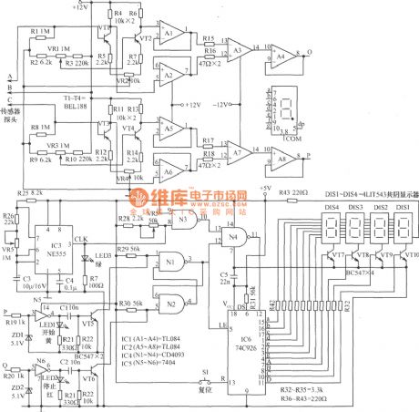
Bibulous rate measuring circuit diagram
Published:2011/4/28 21:37:00 Author:Ecco | Keyword: Bibulous rate , measuring
View full Circuit Diagram | Comments | Reading(899)
Tracking sun photoelectric servo circuit used in chromospheric telescope
Published:2011/4/28 21:01:00 Author:Nicole | Keyword: photoelectric servo, chromospheric telescope
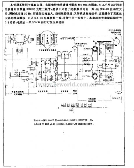
This servo system is used to observe sun. The sunshine is projected onto a Φ50mm round image by optical lens, to fix a 3DU33 photosensitive transistor to the later light slit of AA' and BB', it requires the parameters of two tubes should be as nearly as possible, after 3DG6D differentail amplifier, it is modulated into AC 50Hz, then it is AC amplified. After phase-sensitive rectification, it will be changed into DC singal, it can avoid the zero drift of DC amplifier. The parameters of two 3DG6D also should be coincided, and they are put into the same copper cap. The photoelectric tracing precision of this circuit is 0.8arc-second, the electrical energy is provided by a 300W portable lamp transformer. (View)
View full Circuit Diagram | Comments | Reading(2044)
The typical application circuit diagram of RY927 multi-segment LED driver linear display
Published:2011/4/28 21:12:00 Author:Ecco | Keyword: typical application , multi-segment, LED , driver , linear display
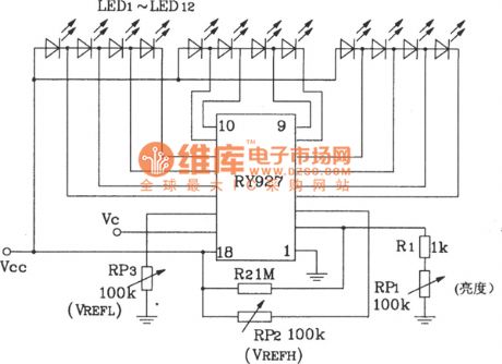
RY927 multi-segment LED driver linear display
(View)
View full Circuit Diagram | Comments | Reading(656)
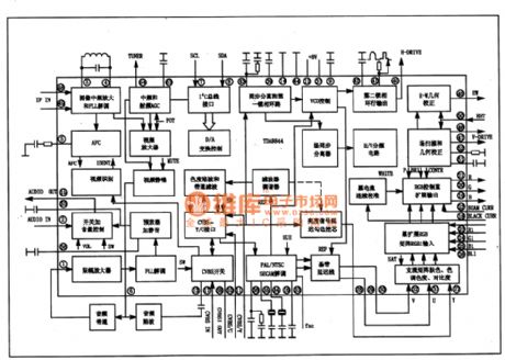
TDA8844 integrated block internal box circuit
Published:2011/4/28 7:34:00 Author:TaoXi | Keyword: integrated block, internal box circuit
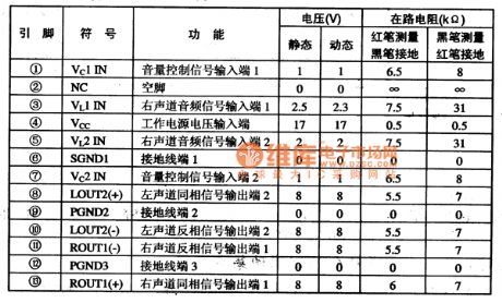
The TDA7057AQ integrated block internal box circuit is as shown in figure 14-19, this IC is in the single 13-pin package, the pin functions and data is shown in table 34.
(View)
View full Circuit Diagram | Comments | Reading(7471)
20-bit LED dot / line conversion display circuit diagram composed of two LM3914
Published:2011/4/28 21:03:00 Author:Ecco | Keyword: 20-bit, LED, dot, line, conversion , display , two
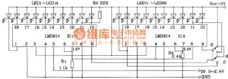
20-bit LED dot / line conversion display circuit diagram composed of two LM3914
(View)
View full Circuit Diagram | Comments | Reading(2931)
VU meter circuit diagram composed of M3916
Published:2011/4/28 20:49:00 Author:Ecco | Keyword: VU meter
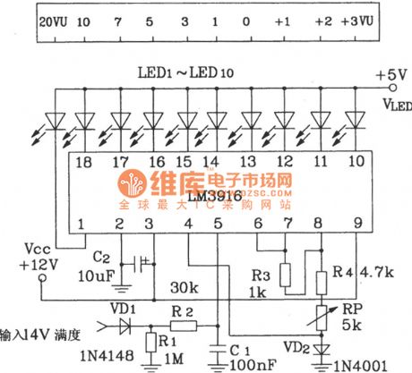
VU meter circuit diagram composed of M3916
(View)
View full Circuit Diagram | Comments | Reading(1836)
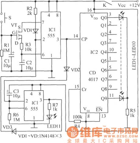
Toilet automatic lighting switch circuit composed of CD4022
Published:2011/4/24 1:20:00 Author:May | Keyword: Toilet automatic lighting switch
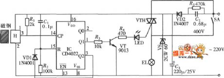
The diagram is Toilet automatic lighting switch which uses gate control type, when someone enter, the door open once, lighting switch breakover, the lamp is lightening. When someone go out the door and open it again, switch cut off and go out. The circuit network is shown in the diagram. The circuit consists of Hall switch, octal count, pulse distributor CD4022 and bidirectional thyristorVTH.
(View)
View full Circuit Diagram | Comments | Reading(3097)
Single frequency sound and light source circuit diagram composed of SGZ07 sound and light alarm IC
Published:2011/4/28 20:33:00 Author:Ecco | Keyword: Single frequency , sound , light, source , alarm IC
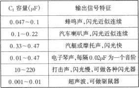
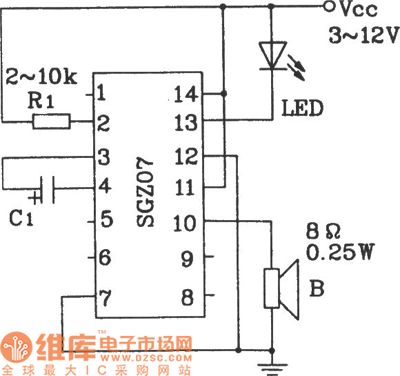
Single frequency sound and light source circuit diagram composed of SGZ07.
The characteristics between C1 and the output signal :
(View)
View full Circuit Diagram | Comments | Reading(807)
ZKB8711 controlled alarm IC for constant temperature automatic control alarm circuit diagram
Published:2011/4/28 20:29:00 Author:Ecco | Keyword: controlled , alarm , IC , constant temperature , automatic control , alarm
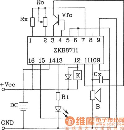
ZKB8711 controlled alarm IC for constant temperature automatic control alarm circuit.
ZKB8711 can be used for temperature control, light control, humidity control, rain and harmful gas detection and alarm control and so on, it has the advantages of several functions, few external components, easy making and so on.
(View)
View full Circuit Diagram | Comments | Reading(1408)
2450MHz final level high power linear amplifier circuit composed of RF2126
Published:2011/4/23 2:22:00 Author:May | Keyword: 2450MHz, final level, high power, linear amplifier
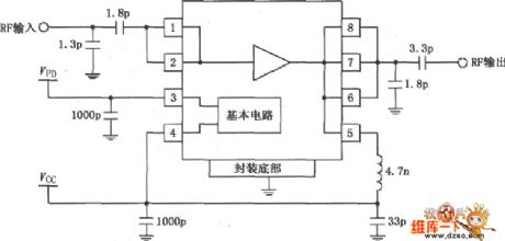
The picture is 2450MHz final level high power linear amplifier circuit composed of RF2126. Radio-frequency signal (RF) inputs by pin 1, and enlarge by power amplifier then output by pin 7 ( 5, 6, 8) . Pin 1 direct coupling with inside amplifier, so add a blocking coupling capacitance out of it. capacity of blocking coupling capacitance is 1.8~2.0μF, input resistance of pin 1 is 50Ω. The capacitance and inductance in the picture is the typical value when frequency is 2450MHz.
(View)
View full Circuit Diagram | Comments | Reading(1462)
Ultrasonic mosquito worm repellant circuit
Published:2011/4/23 1:56:00 Author:May | Keyword: Ultrasonic, mosquito worm repellant
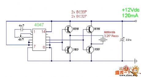
Ultrasonic mosquito worm repellant circuit
It is a very simple ultrasonic mosquito, worm, cockroach repellant circuit.
The circuit is relaxation oscillator consits of CMOS 4047 single shot trigger. It can make its center frequency at about 22kHz by adjusting 4k7. Then it can output by bridge type power tube composed of four transistors. And it can push 3.25 inch Piezo to generate ultrasonic signal.
(View)
View full Circuit Diagram | Comments | Reading(2291)
Bridge isolated amplifier circuit
Published:2011/4/6 5:37:00 Author:may | Keyword: Bridge isolated amplifier
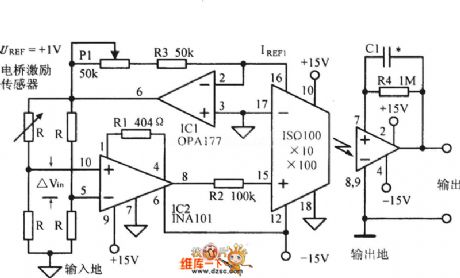
Bridge isolated amplifier circuitis shown in the following diagram:
(View)
View full Circuit Diagram | Comments | Reading(652)
About alternating-current bridge Symmetric incentive circuit
Published:2011/4/2 4:12:00 Author:may | Keyword: alternating-current bridge, Symmetric incentive
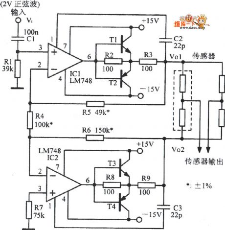
About alternating-current bridge Symmetric incentive circuit is show in the following picture:
(View)
View full Circuit Diagram | Comments | Reading(645)
TDA16846 integrated block internal box circuit
Published:2011/4/28 7:29:00 Author:TaoXi | Keyword: integrated block, internal box circuit
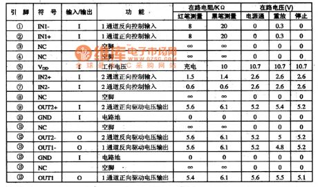
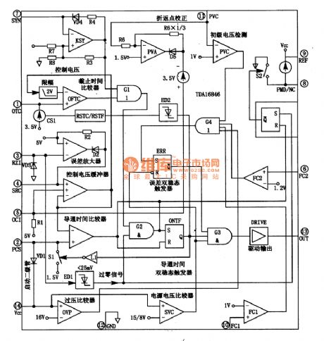
2.Pin functions and data
The TDA7073A is in the 16-pin DIP package, the pin functions and data is shown in table 35, the data is measured from the Amoi VCD-768.
Table 35 The pin functions and data of TDA7073A
(View)
View full Circuit Diagram | Comments | Reading(2811)
Chang antelope car central locking system circuit diagram
Published:2011/4/28 20:02:00 Author:Rebekka | Keyword: Chang antelope car, central locking system
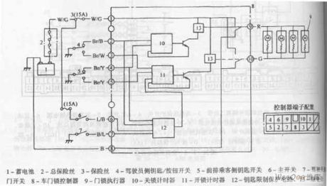
1. Battery 2. The total fuse 3. Fuse 4. The the key / button switch of driver side 5. Front passenger key switch 6. The main switch 8. Car door lock controller 9. Lock actuator 10. Shut the timer 11. unlock timer 12. the key limit protection circuit
Chang antelope car central locking system circuit diagram is shown as above. (View)
View full Circuit Diagram | Comments | Reading(2332)
| Pages:1982/2234 At 2019811982198319841985198619871988198919901991199219931994199519961997199819992000Under 20 |
Circuit Categories
power supply circuit
Amplifier Circuit
Basic Circuit
LED and Light Circuit
Sensor Circuit
Signal Processing
Electrical Equipment Circuit
Control Circuit
Remote Control Circuit
A/D-D/A Converter Circuit
Audio Circuit
Measuring and Test Circuit
Communication Circuit
Computer-Related Circuit
555 Circuit
Automotive Circuit
Repairing Circuit