
Circuit Diagram
Index 2002
Infrared Remote Control Floodlight Circuit Using MC3373
Published:2011/4/26 7:12:00 Author:Robert | Keyword: Infrared Remote Control, Floodlight
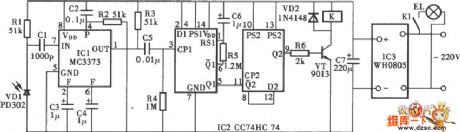
Infrared Remote Control Floodlight Circuit Using MC3373 is shown below:
(View)
View full Circuit Diagram | Comments | Reading(824)
Digital Display Infrared Remote Control Electric Fan Circuit
Published:2011/4/26 7:09:00 Author:Robert | Keyword: Digital Display, Infrared Remote Control, Electric Fan
Digital Display Infrared Remote Control Electric Fan Circuit is shown below:
(View)
View full Circuit Diagram | Comments | Reading(1135)
TC915OP remote control microprocessor integrated circuit
Published:2011/4/26 3:03:00 Author:TaoXi | Keyword: remote control, microprocessor
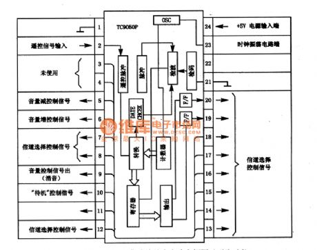
The TC915OP is one kind of remote control microprocessor which is designed to process the pulse from the remote control receiver, the pulse is decoded and transformed by the microprocessor to control each circuit, so this circuit is mainly used for a variety kinds of sound system.
1. TC915OP circuit block diagram and pin functions
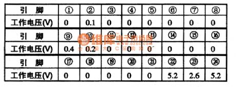
The TC915OP is composed of the remote control pulse discern circuit, check digit circuit, clock oscillation circuit, counter, register and output-drive circuit.etc. The circuit block diagram and pin functions is as shown in figure 1. The pin typical operating voltage is as shown in table 1.
Table 1. The pin typical operating voltage of TC9150P
Figure 1. TC915OP circuit block diagram and pin functions
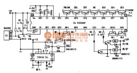
2. Typical application circuit of the TC915OP
The typical application circuit of the TC915OP is as shown. In circuit, IC1 can be used to receive the IR remote control signal, IC3 can be used to remote the volume. Remote control transmitter chip TC9153 can be assorted with the TC915OP.
Figure 2. Typical application circuit of the TC915OP
3. Theworking process of this circuit
4. Fault tips (View)
View full Circuit Diagram | Comments | Reading(3170)
555 darkroom timer circuit 1
Published:2011/4/26 3:23:00 Author:Ecco | Keyword: 555 , darkroom, timer
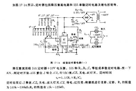
As shown in Figure 17-14, the timer includes buck rectifier circuit and 555 single stable control circuit and relay control. Buck rectifier provides +10 V voltage source for 555 timer. 555 and R1, R2, C1 form a single stable timing circuit, clicking the AN1, the timer starts, 555 sets, J pulls in, CZ2 is lit; CZ1 has no electricity, lights is off. Regular time td = 1.1 (R1 + R2) C1. After timing, J releases, CZ2 loses power, enlarger lamp gets power, the red lamp is lit, CZ1 gets electric, the red light will be like a paper developing and fixing. The resistance of R1 is 140K ~ 530kΩ; the resistance of R2 is 15k ~ 125kΩ.
(View)
View full Circuit Diagram | Comments | Reading(1790)
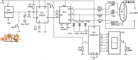
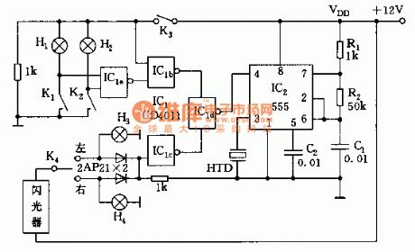
Bus stop indicator (CD4516、CD4514、555、KD9300) circuit
Published:2011/4/26 3:20:00 Author:TaoXi | Keyword: Bus stop, indicator

The bus stop indicator (CD4516、CD4514、555、KD9300) circuit is as shown. This circuit is composed of the 555 monostable delay circuit, counter IC2, decode monitor IC3 and the audio delay circuit.etc.
The monostable delay circuit is composed of the 555 and Rt, Ct, the delay time is td1=1.1RtCt. Counter IC2 can be preset the 4-bit reversible counter CD4516. IC3 is the 4-bit latch 4-16 line decoder. The audio circuit is composed of the music integrated circuit IC4 (KD9300) and the speaker.etc.
If you press the switch AN, IC1 outputs the delay pulse to counter IC2, IC2 pluses 1 (minuses 1) count, the output Q1~Q4 get into the IC3 to be decoded, then feedback to the IC3 by the IC5.
Each time the car go into a station, the driver press the AN to help the passengers to get off easily. (View)
View full Circuit Diagram | Comments | Reading(3059)
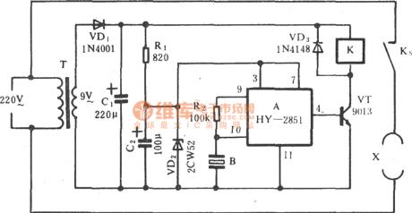
Electronic time relay circuit
Published:2011/4/26 7:05:00 Author:TaoXi | Keyword: Electronic, time relay

The electronic time relay circuit is as shown:
(View)
View full Circuit Diagram | Comments | Reading(532)
The TDA1521 subwoofer circuit and the speaker drawing circuit
Published:2011/4/26 7:11:00 Author:TaoXi | Keyword: subwoofer, speaker drawing

The TDA1521 subwoofer circuit and the speaker drawing circuit is as shown. (View)
View full Circuit Diagram | Comments | Reading(1933)
Figure of the remote control transmitter IC TC9148P
Published:2011/4/26 7:39:00 Author:TaoXi | Keyword: remote control, transmitter

The TC9148P is one kind of remote control remote control transmitter IC that can be used with the microprocessor TC915OP, and this device can be use in variety of sound systems.
1. Pin functions of TC9148P
The TC9148P manifold circuit is composed of the clock oscillator circuit, the key instruction decoding and encoding circuit, the light driver circuit, remote control transmitter drive circuit.etc. The pin functions and pin arrangement of the TC9148P is as shown in figure 1, the operating voltage is as shown in table 1.
Figure 1. The pin functions and pin arrangement of the TC9148P
Table 1. Theoperatingvoltage of TC9148P
2.TC9148P typical application circuit
The TC9148P manifold's typical application circuit is as shown in figure 2.
Figure 2. The TC9148P manifold's typical application circuit
3.Circuit process
VTQ701 and VTQ702 is the output drive circuit of infrared light-emitting diode; LD701, LD702 are the infrared light-emitting diodes; the power supply back circuit is composed of the C702, R701, C701: X701 is the remote control transmitter crystal clock oscillator, the clock oscillation circuit is composed of this oscillator, the C703, C704 and the circuit in pin-2 & pin-3 of TC9148P; VTQ703 is the LED driver output tube of VTQ703.
4.Fault tips (View)
View full Circuit Diagram | Comments | Reading(1294)
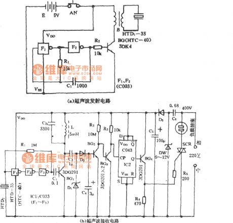
Sub-ultrasonic remote control switch circuit
Published:2011/4/26 7:41:00 Author:TaoXi | Keyword: Sub-ultrasonic, remote control switch

The sub-ultrasonic remote control switch circuit is as shown:
(View)
View full Circuit Diagram | Comments | Reading(495)
Multi-function digital radio circuit
Published:2011/4/26 8:06:00 Author:TaoXi | Keyword: Multi-function, digital radio

Circuit Principle
The AM-FM switch is one kind of FM AM conversion circuit that is composed of the Q2, Q3, R5-R8 and c7, power switch SW3 turns on, Q2 conducts and 03 cuts off, the A/F port outputs the high-level voltage, the voltage from R107 to the pin-15 of u1, so pin-15 of u1 has the high-level voltage and automatically switch to FM band.
The FM high frequency signal which is received by the rod antenna is also amplified by the c101 to the Q101, and then pass the bandpass filter (compose of c104, L101, c105, c106) to pin-12 of u1, and then the FM signal of pin-12 is amplified by the selected frequency amplifier and the frequency selection circuit (compose of PVC, C109, L103). The oscillator circuit is composed of PVC, c110, L104, the LO signal inputs from pin-7 and outputs from pin-14.
The audio signal of u1's pin-23 is coupled by the c123 and outputs from pin-24. w1 is the electronic volume control potentiometer, it controls the level of u1's pin-4 to control the volume. The output audio signal of u1's pin-23 send to the internal power amplifier of u1's pin-24, then the amplified audio signal from pin-27 drives the speaker or headphone. (View)
View full Circuit Diagram | Comments | Reading(2294)
Selected frequency acoustic remote control switch (74LS74) circuit
Published:2011/4/26 8:09:00 Author:TaoXi | Keyword: Selected frequency, acoustic remote control switch
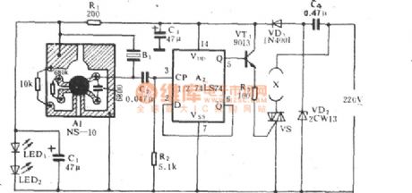
The Selected frequency acoustic remote control switch (74LS74) circuit is as shown:
(View)
View full Circuit Diagram | Comments | Reading(2198)
Fan ultrasonic remote control switch circuit
Published:2011/4/26 8:12:00 Author:TaoXi | Keyword: Fan, ultrasonic remote control switch
The Fan ultrasonic remote control switch circuit is as shown:
(View)
View full Circuit Diagram | Comments | Reading(964)
555 multi-purpose car alarm circuit
Published:2011/4/26 8:17:00 Author:TaoXi | Keyword: multi-purpose, car alarm circuit
As the figure shown, alarm circuit is composed of a 555 and a four 2-input NAND gate circuit. When the oil pressure is too low and the brake pressure is too low, this circuit will issue the warning sound; When the car is steering, this circuit will issue the intermittent sound to tell the driver turn off the turn-light. (View)
View full Circuit Diagram | Comments | Reading(1162)
Self-made PIC microcontroller programmer circuit
Published:2011/4/26 3:54:00 Author:Ecco | Keyword: Self-made , PIC , microcontroller , programmer
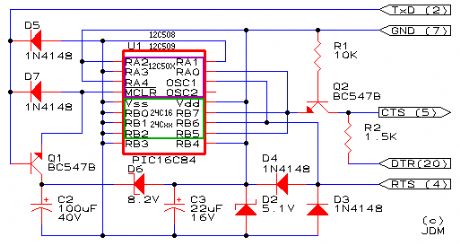
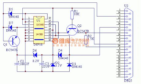
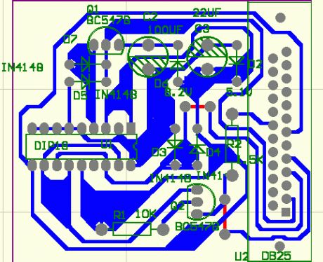
View full Circuit Diagram | Comments | Reading(3822)
Fan sub-ultrasonic remote control switch circuit (1)
Published:2011/4/26 8:44:00 Author:TaoXi | Keyword: Fan, sub-ultrasonic, remote control switch
The fan sub-ultrasonic remote control switch circuit is as shown:
(View)
View full Circuit Diagram | Comments | Reading(571)
crystal diode DDZX5V1BTS internal circuit diagram
Published:2011/4/26 10:28:00 Author:Nancy | Keyword: crystal diode
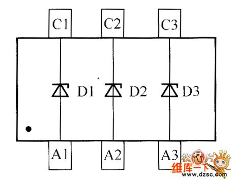
View full Circuit Diagram | Comments | Reading(496)
Inductive headset circuit
Published:2011/4/26 9:13:00 Author:TaoXi | Keyword: Inductive headset
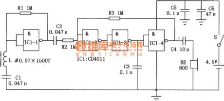
The inductive headset can be used in electronic teaching, home television and stereo audio signal wireless reception applications, this device eliminates the inconvenience of headphone cable, and avoid to interfere other people's rest and study. This circuit is composed of the four NAND gate integrated circuit CD4011 and some external components, the circuit is simple and has excellent sound quality, it is easy to make. (View)
View full Circuit Diagram | Comments | Reading(964)
TC4053 electronic switch control circuit
Published:2011/4/26 19:29:00 Author:TaoXi | Keyword: electronic switch, control circuit
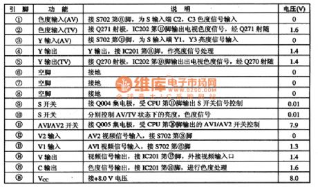
The TC4053 is one kind of electronic switch control IC that can be used in wide range of applications such as color TV, stereo, cordless phone, DVD player.
1.Features
The TC4053 has electronic switch circuit, the switch control circuit and other accessible circuit.
2.Pin functions and data
The TC4053 is in the 16-pin dual inline package and can be used in TCL2911KZ TV, the pin functions and data of the TC4053's TV/AV switch IC is as shown in table 1.
Table 1. The pin functions and data of the TC4053's TV/AV switch IC (View)
View full Circuit Diagram | Comments | Reading(1835)
Along trigger switch circuit composed of MIC5157
Published:2011/4/26 9:26:00 Author:TaoXi | Keyword: Along trigger switch
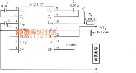
The along trigger switch circuit composed of MIC5157
(View)
View full Circuit Diagram | Comments | Reading(612)
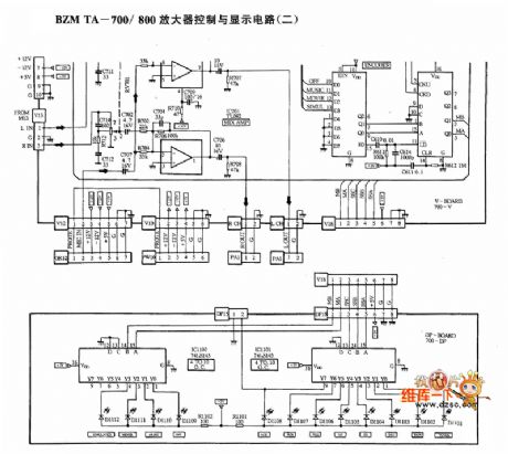
BZMTA-700/800 amplifier control and display circuit diagram
Published:2011/4/26 10:31:00 Author:Nancy | Keyword: amplifier, control and display
(View)
View full Circuit Diagram | Comments | Reading(530)
| Pages:2002/2234 At 2020012002200320042005200620072008200920102011201220132014201520162017201820192020Under 20 |
Circuit Categories
power supply circuit
Amplifier Circuit
Basic Circuit
LED and Light Circuit
Sensor Circuit
Signal Processing
Electrical Equipment Circuit
Control Circuit
Remote Control Circuit
A/D-D/A Converter Circuit
Audio Circuit
Measuring and Test Circuit
Communication Circuit
Computer-Related Circuit
555 Circuit
Automotive Circuit
Repairing Circuit