
Circuit Diagram
Index 2004
Motherboard maintenance drawing board - the trigger circuit
Published:2011/4/26 3:29:00 Author:Ecco | Keyword: Motherboard , maintenance, drawing board, trigger circuit

View full Circuit Diagram | Comments | Reading(1981)
Microcontroller test board circuit 1
Published:2011/4/26 3:41:00 Author:Ecco | Keyword: Microcontroller, test board
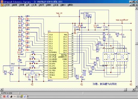
The drawing is a more general test board circuit and suitable for ordinary and stones, gold and many other parts of the Treasure experimental procedure. Anyway, it has strong compatibility, versatility and usability. It can be used in water light, digital control, keyboard control, voice music, oscillator, etc.
(View)
View full Circuit Diagram | Comments | Reading(1529)
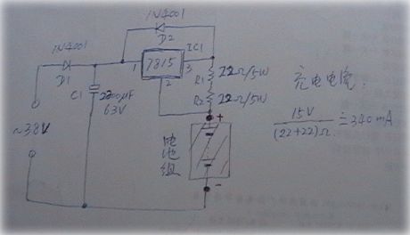
Simple constant current charger circuit
Published:2011/4/26 1:46:00 Author:May | Keyword: constant current charger
View full Circuit Diagram | Comments | Reading(575)
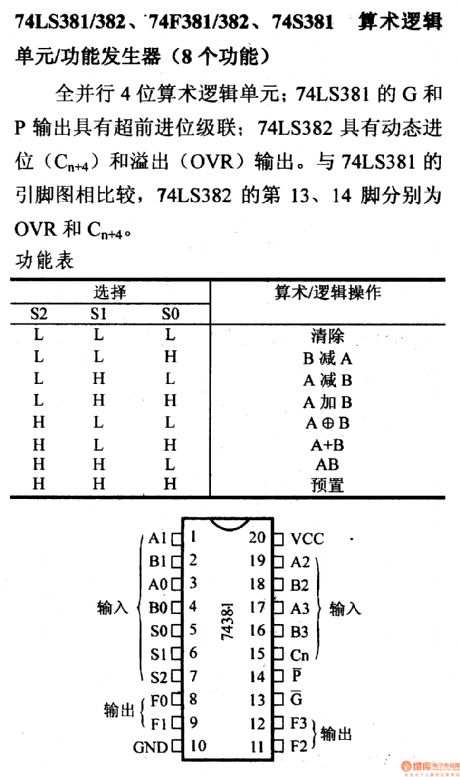
74 series digital circuit 74LS381/382 arithmetic logic unit/association energy generator (eight functions)
Published:2011/4/26 1:57:00 Author:May | Keyword: digital, arithmetic logic unit, association energy generator, eight functions
View full Circuit Diagram | Comments | Reading(1212)
TOYOTA COASTER coach pre-plug(super model) circuit wiring circuit diagram
Published:2011/4/26 3:36:00 Author:Nicole | Keyword: TOYOTA COASTER, coach, pre-plug
View full Circuit Diagram | Comments | Reading(1450)
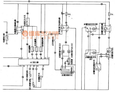
Shenyang JinBei SY6480 light car air conditioning amplifier,back evaporator,back warm braw circuit diagram
Published:2011/4/26 3:19:00 Author:Nicole | Keyword: Shenyang JinBei, light car, air conditioning amplifier, evaporator, warm braw
View full Circuit Diagram | Comments | Reading(1359)
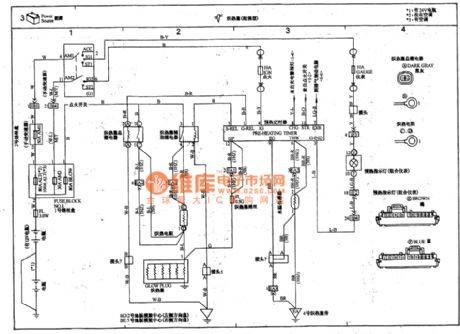
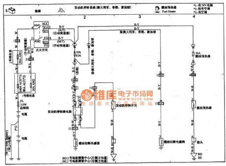
TOYOTA COASTER coach motor run-down system, fuel oil preheater circuit wiring circuit diagram
Published:2011/4/26 3:34:00 Author:Nicole | Keyword: TOYOTA COASTER, coach, motor run-down system, fuel oil preheater
View full Circuit Diagram | Comments | Reading(1109)
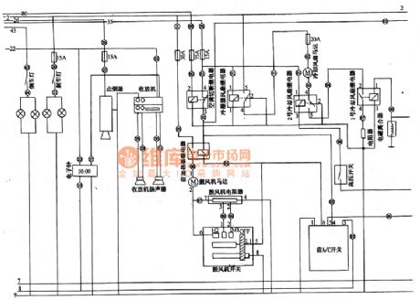
Shenyang JinBei SY6480 light car singal light,radio cassette player,warm braw, former air conditioner circuit diagram
Published:2011/4/26 3:22:00 Author:Nicole | Keyword: Shenyang JinBei, light car, singal light, radio cassette player, warm braw, former air conditioner
View full Circuit Diagram | Comments | Reading(772)
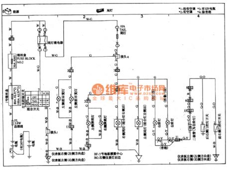
TOYOTA COASTER coach back lamp circuit wiring circuit diagram
Published:2011/4/26 3:24:00 Author:Nicole | Keyword: TOYOTA COASTER, coach, back lamp
View full Circuit Diagram | Comments | Reading(908)
TOYOTA COASTER coach headlight circuit wiring circuit diagram
Published:2011/4/26 3:27:00 Author:Nicole | Keyword: TOYOTA COASTER, coach, headlight
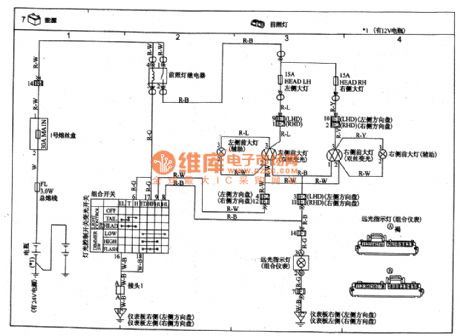
View full Circuit Diagram | Comments | Reading(4107)
TOYOTA COASTER coach exhaust brake circuit wiring circuit diagram
Published:2011/4/26 3:31:00 Author:Nicole | Keyword: TOYOTA COASTER, coach, exhaust brake
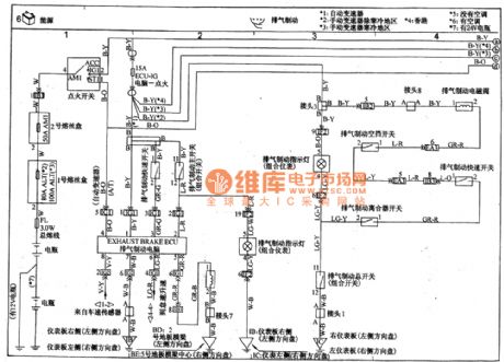
View full Circuit Diagram | Comments | Reading(7919)
TOYOTA COASTER coach exhaust brake(connection to previous page) circuit wiring circuit diagram
Published:2011/4/26 3:31:00 Author:Nicole | Keyword: TOYOTA COASTER, coach, exhaust brake
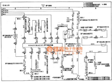
View full Circuit Diagram | Comments | Reading(3201)
Using KD-28 as siren generator circuit diagram
Published:2011/4/26 3:30:00 Author:Rebekka | Keyword: Siren generator
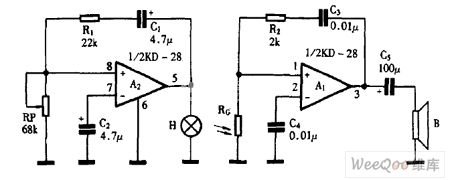
Using KD-28 as siren generator circuit diagram is shown as above. (View)
View full Circuit Diagram | Comments | Reading(490)
Using KD-28 as voice switching circuit diagram
Published:2011/4/26 3:30:00 Author:Rebekka | Keyword: voice switching
Using KD-28 as voice switching circuit diagram is shown as above. (View)
View full Circuit Diagram | Comments | Reading(785)
UM3758-108A/AM New single-chip encoding and decoding circuit diagram
Published:2011/4/24 4:50:00 Author:Rebekka | Keyword: single-chip , encoding and decoding
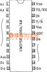
UM3758-108A/AM shape pin map
UM3758-108A/AM encoding and decoding integrated circuit has the function of encoding sending and decoding receiving. The device itself has 10-bit three-state address inputs and 8-bit latch functions with a variety of ways to achieve long-distance remote control. It has the unique dual-duplex transceiver remote control and body functions. At present, this device is widely used in automotive, defense of the motherland, safe, mobile phones and military communications and other aspects of remote control, alarm, and password control circuits.
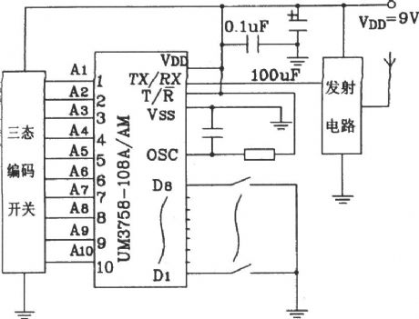
Electrical parameters UM3758-108A/AM electrical parameters are identical. The main electrical parameters are: Working voltage range 3 ~ 12V, typical application voltage of 6V or 9V; Receiving input high minimum 4V, low maximum value of 2V; Other input level VIH = (VDD-0.5V ) ~ VDD, VIL = 0.5V; Output level VoH = (VDD-0.5V) ~ VDD, VOL = 0 ~ 1V; Data output current is ± 10mA (level is VDD / 2 时); TX / Rx-ended output current up-40mA or +20 mA; Chip operating clock oscillation frequency fosc = 160kHz.
Remote code transmission circuit composed of UM3758-108A/AM
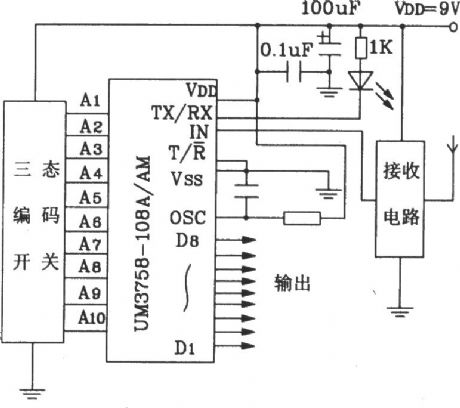
Remote decode transmission circuit composed of UM3758-108A/AM
(View)
View full Circuit Diagram | Comments | Reading(2072)
YN5049/5050 Infrared remote control receiver typical application circuit diagram
Published:2011/4/22 2:53:00 Author:Rebekka | Keyword: Infrared remote control, receiver typical application
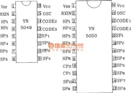
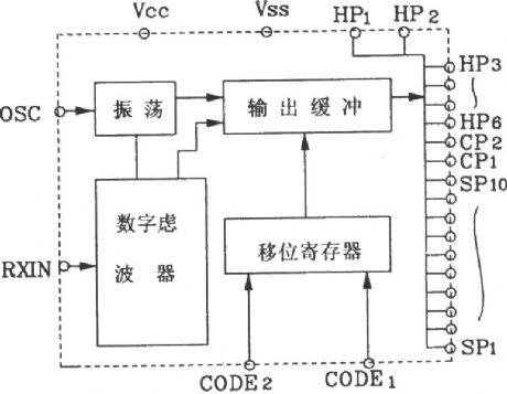
YN5049/5050 multiple infrared remote receiver is a dedicated remote control receiver IC that uses with YN5048 multiple infrared remote control transmitter fetters. They are mainly used in TV, stereo, VCR and other home appliances remote areas. There are similar models BL9150, TC9150.
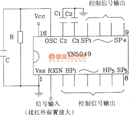
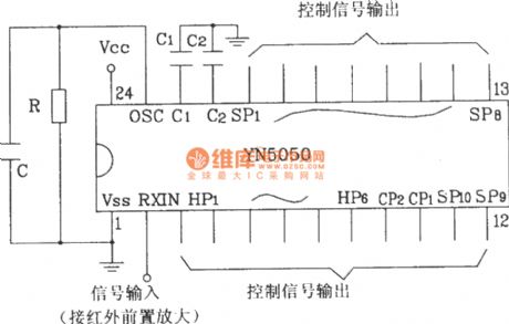
YN5049/5050 shape pin map.
YN5050 internal block diagram.
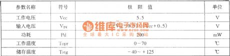
YN5049/5050 infrared remote control receiver limit operating parameters.
(1)
(2)
(1), (2) are infrared remote control receiver YN5049/5050 typical application circuit
(View)
View full Circuit Diagram | Comments | Reading(1706)
Ratio motor wireless remote control circuit diagram
Published:2011/4/20 4:19:00 Author:Rebekka | Keyword: Ratio motor wireless , remote control
Ratio motor wireless remote control transmitter circuit.
Ratio motor wireless remote control receiver circuit.
IC2 is the LM386. It is a good performance low-power audio amplifier integrated circuits. It is widely used.
(View)
View full Circuit Diagram | Comments | Reading(3047)
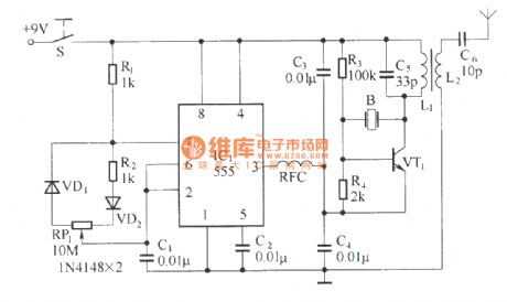
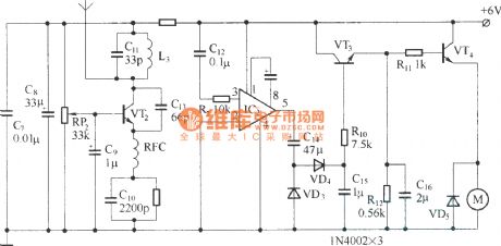
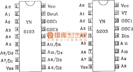
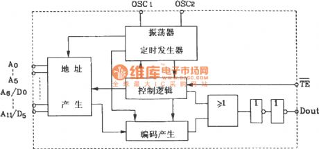
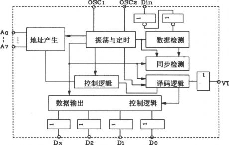
Composed of YN5103IR/YN5203 encoder decoder matching infrared remote control application circuit diagram
Published:2011/4/21 10:12:00 Author:Rebekka | Keyword: infrared remote control application , encoder decoder matching
The matching use of YN5103 and decoder YN5203 can be widely used in automotive, building door security systems, home appliances and other aspects of multi-channel remote control.
YN5103/5203 shape pin map.
YN5103 internal block diagram.
YN5203 internal block diagram.
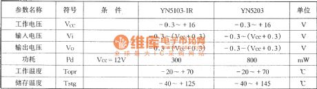
YN5103/YN5203 encoder / decoder, limits the working parameters:
General application YN5203 oscillation frequency of the decoder should be 2.5 to 8 times of YN5103-IR encoder oscillation frequency. Following table shows the three groups when paired with resistance.
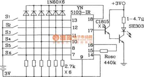
Infrared encoder composed of YN5103-IR.
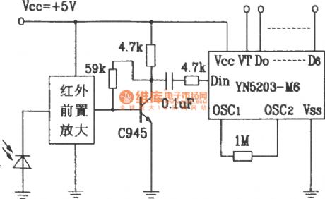
IR decoding circuit composed of YN5203-M6.
Oscillation resistor Rosc is YN5103: 440k, YN5203: 1M.
(View)
View full Circuit Diagram | Comments | Reading(1938)
Using LA4112 as regulated power supply circuit diagram
Published:2011/4/26 3:19:00 Author:Rebekka | Keyword: regulated power supply
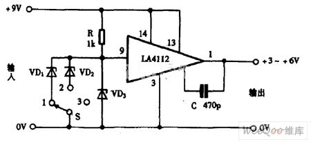
Using LA4112 as regulated power supply circuit diagram is shown as above. (View)
View full Circuit Diagram | Comments | Reading(1299)
Using LB1405 as pre-amplifier circuit diagram
Published:2011/4/26 3:17:00 Author:Rebekka | Keyword: pre-amplifier circuit
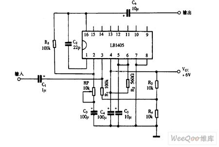
Using LB1405 as pre-amplifier circuit diagram is shown as above. (View)
View full Circuit Diagram | Comments | Reading(4877)
| Pages:2004/2234 At 2020012002200320042005200620072008200920102011201220132014201520162017201820192020Under 20 |
Circuit Categories
power supply circuit
Amplifier Circuit
Basic Circuit
LED and Light Circuit
Sensor Circuit
Signal Processing
Electrical Equipment Circuit
Control Circuit
Remote Control Circuit
A/D-D/A Converter Circuit
Audio Circuit
Measuring and Test Circuit
Communication Circuit
Computer-Related Circuit
555 Circuit
Automotive Circuit
Repairing Circuit