
Circuit Diagram
Index 2021
Separate-excited Crossed Oscillator Used in Quad Cycled Lights Controller Circuit
Published:2011/4/21 20:01:00 Author:Sue | Keyword: Separate-excited, Crossed, Oscillator, Quad Cycled Lights Controller
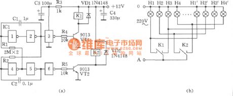
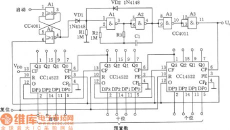
As seen in the figure is the separate-excited crossed oscillator used quad cycled colored lights controller circuit. In this circuit, the quad cycled colored lights can be controlled by only two single contact relays 4088. The operation principle is: The separated-excited crossed oscillatory circuit composed of IC1 6 NOT gate CD4069 and C1,C2,R1,R2 has a direct control over crystal triode VT1 and VT2. The driving relay K1 and K2 realise the crossed split-phase output, that is after K1 is connected, K2 will be connected, then K2 is cut off after K1 is cut off, and this process makes a circle. In this figure, (b) is the connection diagram of colored lights. (View)
View full Circuit Diagram | Comments | Reading(437)
Self-excited Multivibrator Circuit Composed of CC4093
Published:2011/4/21 21:01:00 Author:Sue | Keyword: Self-excited, Multivibrator
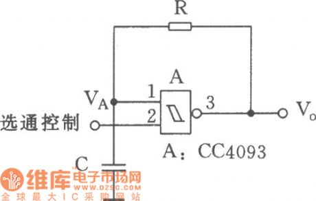
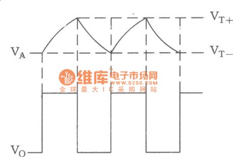
When the multivibrator is composed of Schmitt trigger, only a resistance and a capacitor need to be circumscribed. This circuit is designed for the low frequency oscillator with controllable oscillation and less demand on accuracy. As seen in the figure is the self-excited multivibrator composed of Schmitt trigger CC4093 with 4-2 imput. As to the waveform, see the figure below:
(View)
View full Circuit Diagram | Comments | Reading(593)
Circuit of Self-excited Multivibrator to Improve Waveform and Stability
Published:2011/4/20 21:49:00 Author:Sue | Keyword: Self-excited, Multivibrator, Waveform, Stability
View full Circuit Diagram | Comments | Reading(493)
Timer circuit with Miller integrator
Published:2011/4/24 21:30:00 Author:Nicole | Keyword: timer, Miller integrator
Miller integrator's negative feedback is connected from transistor collector to its base by capacitance. It adopts composite pipe to improve the current amplification.
After pressing key T, the capacitance is charged to power voltage. The time constant of this process is 33ms. Relay is no delay pull-in. When the key is cut off, Miller integrator starts to work. (View)
View full Circuit Diagram | Comments | Reading(728)
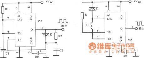
Circuit of Multivibrator Composed of Integrated Circuit 555
Published:2011/4/20 21:48:00 Author:Sue | Keyword: Multivibrator, Integrated, 555
View full Circuit Diagram | Comments | Reading(611)
PLL Pulse Generator(74HC4060、TC9122P) Circuit
Published:2011/4/21 19:56:00 Author:Sue | Keyword: PLL, Pulse, Generator, 74HC4060, TC9122P
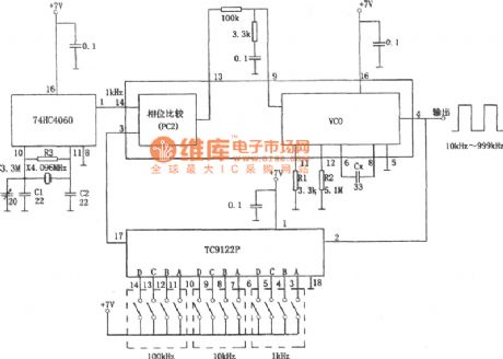
As shown in the figure is Phase-Locked Loop(PLL) pulse generating circuit. When PLL divides crystal oscillator, the 1kHz signal gained can be used as the step frequency,and there will be pulse waveforms of 10kHz 999kHz at the end of output. The 74HC4060 integrated block is an integrated chip with NOR gates and 1/2n dividing circuit inside. And the NOR gate and crystal oscillator with a frequency of 4.096MHz will constitute an oscillatory circuit, while dividing circuit gets the basic frequency signal of 1kHz by dividing it. TC9122P is a high-speed programmable counter whose dividing frequency is decided by code BCD. The program-based range of divding frequency ratio is 8-999,and this circuit works on the range of 10-999. Inside 74HC4060 there are 3 kinds of phase comparators, one of which,comarators PC2, controls the feedback by comparing the output frequency with the basic frequency. VC0's oscillator frequency is decided by Cx, R1 andR2. The minimum andmaximum frequencies are: fmin=1/R2(Cx+32pF) , fmax=1/R1(Cx+32pF) (View)
View full Circuit Diagram | Comments | Reading(5371)
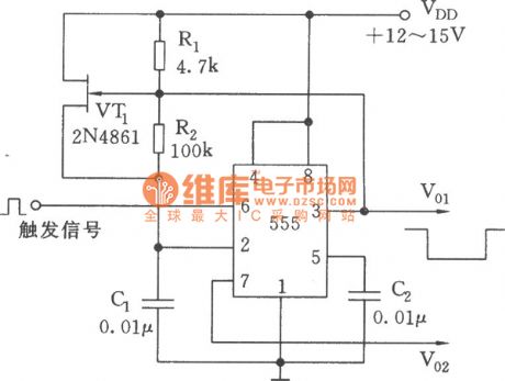
Negative Timing Pulse Generator(555) Circuit with Two-way Output
Published:2011/4/20 21:44:00 Author:Sue | Keyword: Negative, Timing, Pulse, Generator, Two-Way, 555
View full Circuit Diagram | Comments | Reading(1333)
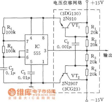
Zero Symmetric Bidirectional Pulse Wave Generator Circuit
Published:2011/4/20 21:42:00 Author:Sue | Keyword: Zero Symmetric, Bidirectional, Pulse Wave, Generator
View full Circuit Diagram | Comments | Reading(765)
Pulser Generator Circuit Composed of CC4516 with Controlled Pulsewidth
Published:2011/4/20 21:39:00 Author:Sue | Keyword: Pulse, Generator, Controlled Pulsewidth
View full Circuit Diagram | Comments | Reading(434)
Quantitative Pulse Generator Circuit
Published:2011/4/20 21:35:00 Author:Sue | Keyword: Quantitative, Pulse, Generator
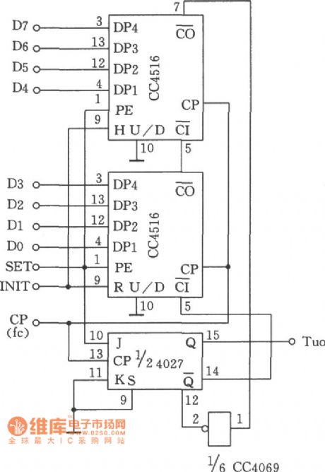
This circuit is mainly used to control the amount of rotation of step electric motors. The joint angle of a step electric motor is subject to the number of pulses input by the circular distributor. In this circuit, the quantitative pulses can be set to 999 at most in a random manner. (View)
View full Circuit Diagram | Comments | Reading(549)
1/86400Hz Pulse Generator Circuit
Published:2011/4/22 21:40:00 Author:Sue | Keyword: Pulse, Generator, 1/86400Hz
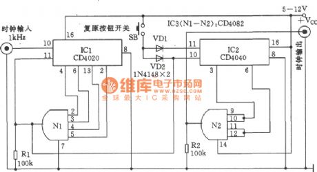
As illustrated, in the circuit it is able to input a clock pulse of 1Hz every 24 hours, which can be generated by digital clock. It can offer the a.m. or p.m. instructions for those without this function, or to be used to preset the date of digital calendars. Also it can serve as a reliable alarm trigger at a particular time. (View)
View full Circuit Diagram | Comments | Reading(790)
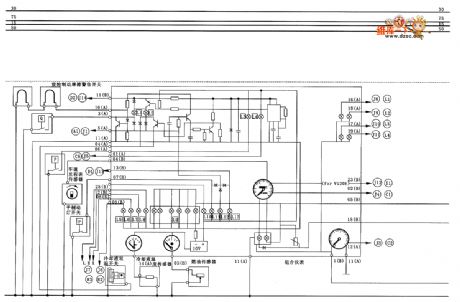
Zastava CA7200E3(L) type lighting and signalling system circuit diagram
Published:2011/4/24 21:23:00 Author:muriel | Keyword: Zastava, lighting and signalling system
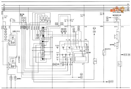
Zastava CA7200E3(L) type lighting and signalling system circuit diagram is as shown
(View)
View full Circuit Diagram | Comments | Reading(489)
Zastava CA7200E3(L) type instrument and signalling system circuit diagram
Published:2011/4/24 21:26:00 Author:muriel | Keyword: Zastava, instrument and signalling system
Zastava CA7200E3(L) type instrument and signalling system circuit diagram is as shown
(View)
View full Circuit Diagram | Comments | Reading(484)
Zastava CA7200E3(L) type radio cassette player and center gate lock system circuit diagram
Published:2011/4/24 21:22:00 Author:muriel | Keyword: Zastava , radio cassette player, center gate lock system
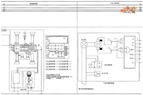
Zastava CA7200E3(L) type radio cassette player and center gate lock system circuit diagram is as shown
(View)
View full Circuit Diagram | Comments | Reading(677)
Zastava CA7200E3(L) type buzzer, indoor light and cigar lighter circuit diagram
Published:2011/4/24 21:20:00 Author:muriel | Keyword: Zastava , buzzer, indoor light, cigar lighter
Zastava CA7200E3(L) type buzzer, indoor light and cigar lighter circuit diagram is as shown
(View)
View full Circuit Diagram | Comments | Reading(589)
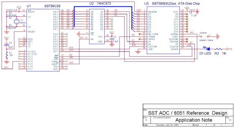
SST89C58 Electronic plate circuit and code
Published:2011/4/24 20:42:00 Author:Ecco | Keyword: Electronic plate , code
View full Circuit Diagram | Comments | Reading(678)
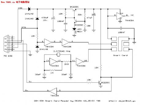
The DIY information of SIMMAX on GSM mobile phone
Published:2011/4/24 21:16:00 Author:Ecco | Keyword: DIY information , SIMMAX , GSM mobile phone
View full Circuit Diagram | Comments | Reading(1070)
DONGFENG CITROEN XSARA starter and generator(manual transmission) circuit diagram
Published:2011/4/24 21:07:00 Author:muriel | Keyword: DONGFENG CITROEN XSARA, starter, generator(manual transmission)
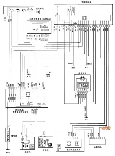
DONGFENG CITROEN XSARA starter and generator(manual transmission) circuit diagram is as shown
(View)
View full Circuit Diagram | Comments | Reading(3982)
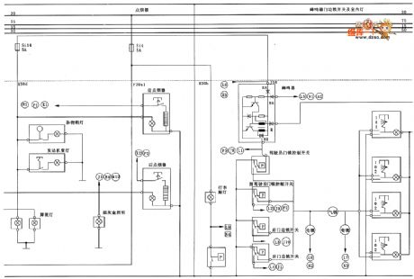
Zastava CA7200E3(L) type center gate lock system(one) circuit diagram
Published:2011/4/24 21:18:00 Author:muriel | Keyword: Zastava , center gate lock system
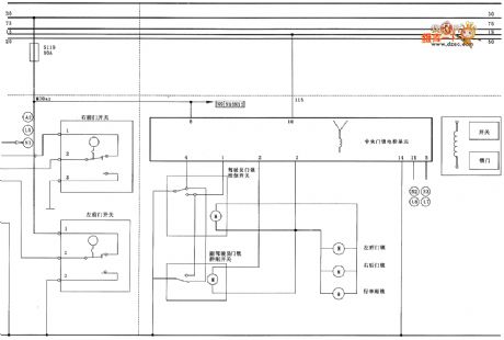
Zastava CA7200E3(L) type center gate lock system circuit diagram is as shown
(View)
View full Circuit Diagram | Comments | Reading(514)
Zastava CA7200E3(L) type engine fuel injection system (one) circuit diagram
Published:2011/4/24 21:11:00 Author:muriel | Keyword: Zastava, engine fuel injection system
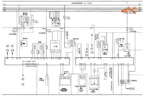
Zastava CA7200E3(L) type engine fuel injection system (one) circuit diagram is as shown
(View)
View full Circuit Diagram | Comments | Reading(600)
| Pages:2021/2234 At 2020212022202320242025202620272028202920302031203220332034203520362037203820392040Under 20 |
Circuit Categories
power supply circuit
Amplifier Circuit
Basic Circuit
LED and Light Circuit
Sensor Circuit
Signal Processing
Electrical Equipment Circuit
Control Circuit
Remote Control Circuit
A/D-D/A Converter Circuit
Audio Circuit
Measuring and Test Circuit
Communication Circuit
Computer-Related Circuit
555 Circuit
Automotive Circuit
Repairing Circuit