
Circuit Diagram
Index 2023
XSARA headlamp circuit diagram
Published:2011/4/24 20:39:00 Author:muriel | Keyword: XSARA, headlamp
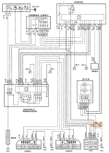
XSARA headlamp circuit diagram is as shown
(View)
View full Circuit Diagram | Comments | Reading(601)
GUANGZHOU Fit windshield wiper and scrubber circuit diagram
Published:2011/4/24 20:31:00 Author:muriel | Keyword: GUANGZHOU Fit , windshield wiper, scrubber

GUANGZHOU Fit windshield wiper and scrubber circuit diagram is as shown
(View)
View full Circuit Diagram | Comments | Reading(824)
GUANGZHOU HONDA Accord engine circuit diagram
Published:2011/4/24 20:24:00 Author:muriel | Keyword: GUANGZHOU HONDA Accord, engine
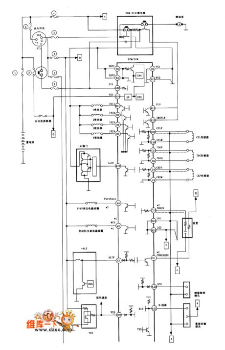
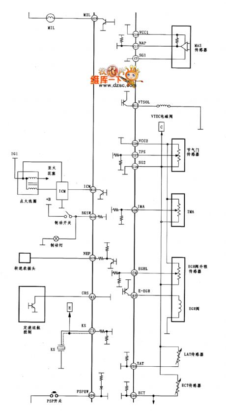
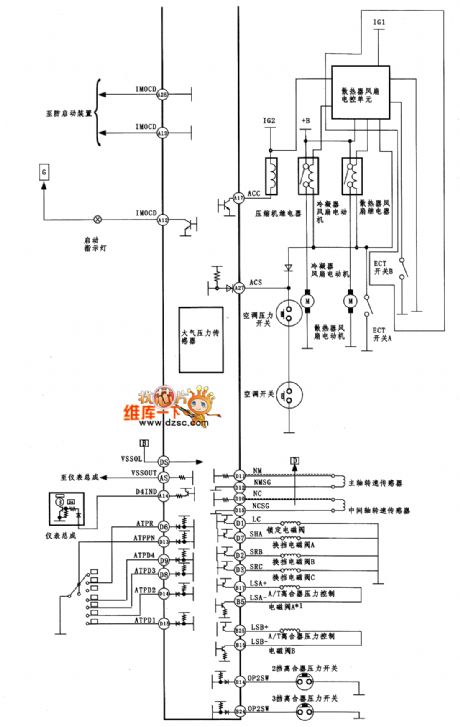
GUANGZHOU HONDA Accord engine circuit diagram is as shown
(View)
View full Circuit Diagram | Comments | Reading(598)
GUANGZHOU Fit motor-driven rearview mirror circuit diagram
Published:2011/4/24 20:33:00 Author:muriel | Keyword: GUANGZHOU Fit, motor-driven rearview mirror
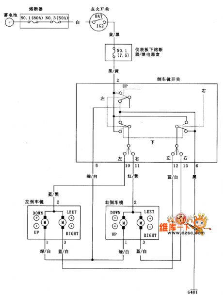
GUANGZHOU Fit motor-driven rearview mirror circuit diagram is as shown
(View)
View full Circuit Diagram | Comments | Reading(527)
Portable Loudspeaker Circuit
Published:2011/4/24 0:16:00 Author:TaoXi | Keyword: Portable, Loudspeaker
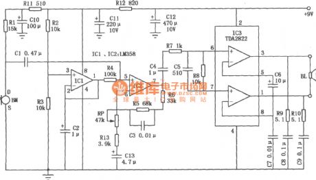
The Portable Loudspeaker Circuit is as shown. This device is composed of a dual op amp and a dual power amplifier IC, the amplifier class is BTL bridge circuit, in the same supply voltage condition, the output power is four times of circuit A. And this device is suitable for a wide supply voltage range (6V to 15V). (View)
View full Circuit Diagram | Comments | Reading(1009)
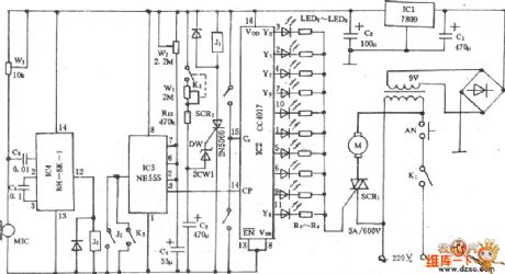
Audio Commentary Synchronous Controller Circuit
Published:2011/4/23 23:10:00 Author:TaoXi | Keyword: Audio Commentary, Synchronous Controller
The Audio Commentary Synchronous Controller Circuit is as shown:
(View)
View full Circuit Diagram | Comments | Reading(500)
Solid Recorder Circuit
Published:2011/4/24 0:34:00 Author:TaoXi | Keyword: Solid Recorder
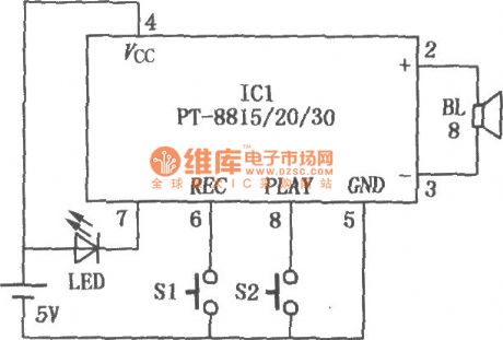
The Solid Recorder Circuit is as shown. ICl is the fool type IC of voice recording & broadcasting (PT-8815/20/30). When this device is working, we press the recording switch Sl to light the LED, this means the ICl is under the recording mode, so we can record to the speaker BL. After recording, we press the playback switch S2 to play the sound we just recorded. The circuit can be widely used in various of occasions that need voice prompt. (View)
View full Circuit Diagram | Comments | Reading(3304)
GUANGZHOU Fit motor-driven car window circuit diagram
Published:2011/4/24 20:34:00 Author:muriel | Keyword: GUANGZHOU Fit, motor-driven car window
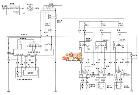
GUANGZHOU Fit motor-driven car window circuit diagram is as shown
(View)
View full Circuit Diagram | Comments | Reading(512)
XSARA loudspeaker circuit diagram
Published:2011/4/24 20:41:00 Author:muriel | Keyword: XSARA, loudspeaker
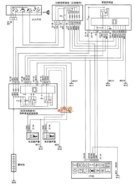
XSARA loudspeaker circuit diagram is as shown
(View)
View full Circuit Diagram | Comments | Reading(628)
GUANGZHOU Fit entrance light control system circuit diagram
Published:2011/4/24 20:36:00 Author:muriel | Keyword: GUANGZHOU Fit , entrance light control system
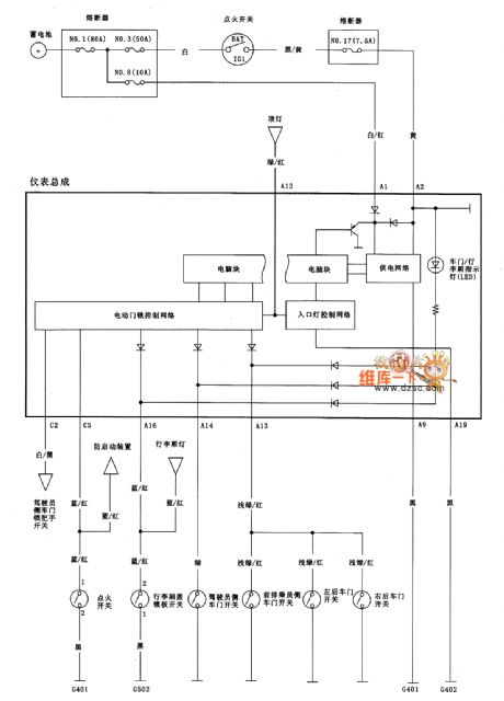
GUANGZHOU Fit entrance light control system circuit diagram is as shown
(View)
View full Circuit Diagram | Comments | Reading(595)
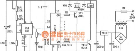
Variable-Tone Signal Generating Circuit
Published:2011/4/22 21:40:00 Author:Sue | Keyword: Variable-Tone, Signal, Generating
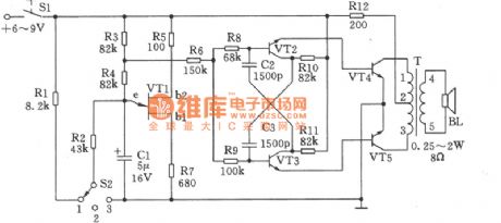
Variable-tone signal generating circuit can be used in making different types of alarms, and can also in toys which will bring about a lot of fun. As seen in the figure, this circuit comprises relaxation oscillatory composed of unijunction transistor VT1, multivibrator composed of VT2, VT3, and B-type push pull power amplifier composed of VT4, VT5. The selection of component is as follows.
VT1: Double-base diode BT33C, the direct current resistance RBB of which between b1 and b2 should be 3~10kΩ.
VT2,VT3: 9013,50≤β≤85.
VT4,VT5: 3DGl28,50≤β≤65.
(In order to guarantee the accuracy of frequency, the parameters of geminate transistors VT2 and VT3, VT4 and VT5 should be as consistent as possible.)
Power switch S1: KNX(1×1).
Selected switch S2: KZX-1-3W1D(band switch).
Audio transformer T: can-type ferrite MTT22, high-intensity enamelled wire L1-2ΦO.13mm, coiled by 380 turns; high-intensity enamelled wire L2-3ΦO.13mm, coiled by 380 turns; high-intensity enamelled wire L4-5Φ0.19mm, coiled by 46 turns.
Resistance R12: 1/2 WRJ-type
Other resistances: 1/8WRJ-type. (View)
View full Circuit Diagram | Comments | Reading(519)
Squirrel Cage Autotransformer Motor Starter Circuit
Published:2011/4/23 3:02:00 Author:Robert | Keyword: Squirrel Cage, Autotransformer, Motor Starter
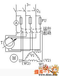
Squirrel Cage Autotransformer Motor Starter Circuit is shown above. (View)
View full Circuit Diagram | Comments | Reading(1449)
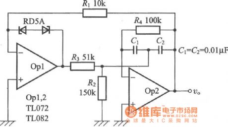
Wien Bridge Oscillator Circuit
Published:2011/4/22 20:33:00 Author:Sue | Keyword: Wien Bridge, Oscillator
View full Circuit Diagram | Comments | Reading(2968)
Squirrel Cage Motor Direct Starting Circuit
Published:2011/4/23 3:07:00 Author:Robert | Keyword: Squirrel Cage, Motor, Direct Starting
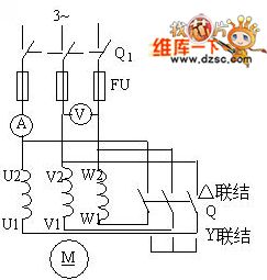
Squirrel Cage Motor Direct Starting Circuit is shown above. (View)
View full Circuit Diagram | Comments | Reading(852)
Terman Oscillator Circuit
Published:2011/4/22 20:42:00 Author:Sue | Keyword: Terman, Oscillator
In Wien Bridge Circuit, connect J-FET between resistance R3 and R4, then replace operational amplifier with transistor. Circuit made in this way is called Terman oscillator circuit. (View)
View full Circuit Diagram | Comments | Reading(576)
Electric Fan Multi-Function Sound Control Speed Governing Circuit
Published:2011/4/23 3:09:00 Author:Robert | Keyword: Electric Fan, Multi-Function, Sound Control, Speed Governing
Electric Fan Multi-Function Sound Control Speed Governing Circuit is shown below:
(View)
View full Circuit Diagram | Comments | Reading(619)
Eye Protechtion Circuit
Published:2011/4/23 3:11:00 Author:Robert | Keyword: Eye Protechtion
Eye Protechtion Circuit is shown below:
(View)
View full Circuit Diagram | Comments | Reading(635)
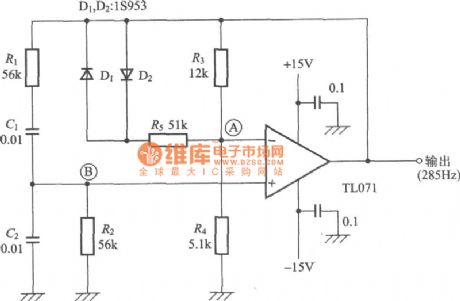
T-Type Bridge Oscillator Circuit
Published:2011/4/22 20:48:00 Author:Sue | Keyword: T-Type Bridge, Oscillator
View full Circuit Diagram | Comments | Reading(765)
Rocket Launcher Simulation Circuit
Published:2011/4/23 3:13:00 Author:Robert | Keyword: Rocket Launcher, Simulation
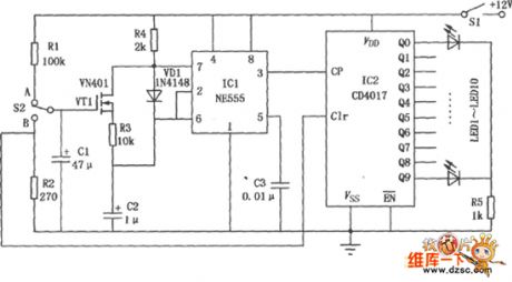
Rocket Launcher Simulation Circuit is shown as below:
(View)
View full Circuit Diagram | Comments | Reading(768)
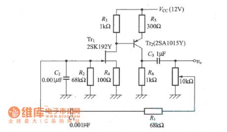
2.5kHz Wien Bridge Signal Generator Circuit
Published:2011/4/22 22:17:00 Author:Sue | Keyword: 2.5kHz, Wien Bridge, Signal, Generator
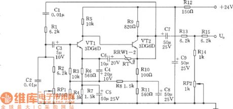
This signal generator is a kind of RC Wien Bridge oscillator Circuit. As seen in the figure, secondary direct-coupling amplifier is composed of triode VT1 and VT1. The input is in a form of bootstrap, making the input impedance much higher to reduce effects on phase-shifting circuit RC. As to the T-type attenuator connected to the output terminal, on one hand, it can meet the demands of output impedance, on the other hand it can reduce the effects that loads have on RC. In this case, the frequency stability of the oscillator depends on that of RC. Because of low-temperature coefficient of RC, the frequency of this oscillator is stable(25℃±15℃, change range ≤±5Hz). (View)
View full Circuit Diagram | Comments | Reading(688)
| Pages:2023/2234 At 2020212022202320242025202620272028202920302031203220332034203520362037203820392040Under 20 |
Circuit Categories
power supply circuit
Amplifier Circuit
Basic Circuit
LED and Light Circuit
Sensor Circuit
Signal Processing
Electrical Equipment Circuit
Control Circuit
Remote Control Circuit
A/D-D/A Converter Circuit
Audio Circuit
Measuring and Test Circuit
Communication Circuit
Computer-Related Circuit
555 Circuit
Automotive Circuit
Repairing Circuit