
Circuit Diagram
Index 2027
MAX712/MAX713 pin arrangement mode
Published:2011/4/22 4:46:00 Author:Nicole | Keyword: pin arrangement
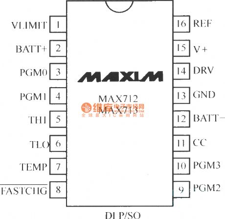
MAX712/MAX713 series are fast charging management chip produced by Maxim Company. MAX712/MAX713 chip is suitable for the charging of 1~16 bit Ni-MH battery or Ni-Cd battery. The pin arrangement diagram is shown as below:
(View)
View full Circuit Diagram | Comments | Reading(898)
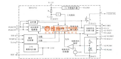
MAX712 internal structure block diagram
Published:2011/4/22 4:39:00 Author:Nicole | Keyword: internal structure
View full Circuit Diagram | Comments | Reading(790)
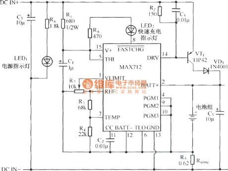
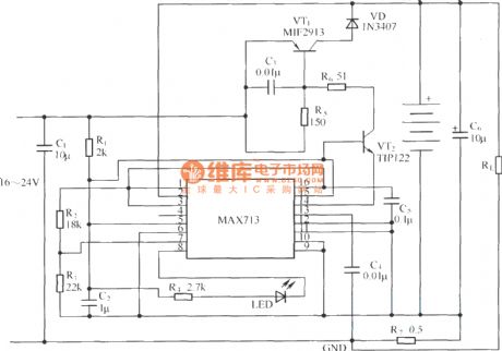
MAX712 application circuit(charging circuit)
Published:2011/4/22 4:38:00 Author:Nicole | Keyword: charging
View full Circuit Diagram | Comments | Reading(2089)
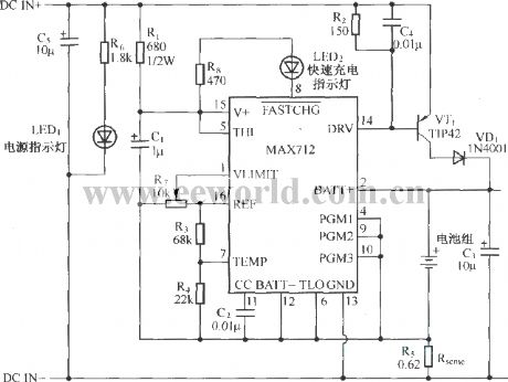
MAX712 application circuit charging circuit
Published:2011/4/22 4:37:00 Author:Nicole | Keyword: charging
View full Circuit Diagram | Comments | Reading(1594)
MAX713 application circuit under linear model
Published:2011/4/22 4:36:00 Author:Nicole | Keyword: linear model
View full Circuit Diagram | Comments | Reading(2562)
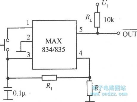
MAX834/835 typical application circuit
Published:2011/4/22 4:33:00 Author:Nicole | Keyword: typical application
View full Circuit Diagram | Comments | Reading(525)
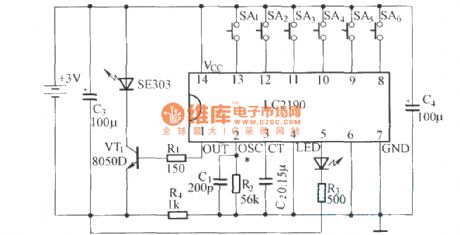
LC2190 principle and application circuit diagram
Published:2011/4/20 1:30:00 Author:Rebekka | Keyword: principle and application
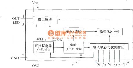
LC219 is a modified LC2190 circuit, the internal principle of the improved emission encoder circuit is shown as above.
Application circuit diagram is shown as above. (View)
View full Circuit Diagram | Comments | Reading(1194)
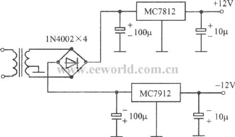
±12V regulated power supply composed of MC7812 positive pressure and MC7912MC(negative pressure)
Published:2011/4/22 4:16:00 Author:Nicole | Keyword: ±12V regulated power supply, positive pressure, negative pressure
View full Circuit Diagram | Comments | Reading(948)
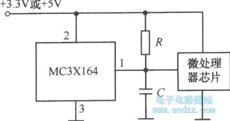
Reset circuit composed of MC3X164 series
Published:2011/4/22 4:18:00 Author:Nicole | Keyword: reset
View full Circuit Diagram | Comments | Reading(472)
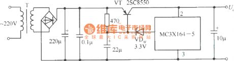
Overvoltage protection circuit composed of MC3X164 series
Published:2011/4/22 4:19:00 Author:Nicole | Keyword: Overvoltage protection
View full Circuit Diagram | Comments | Reading(498)
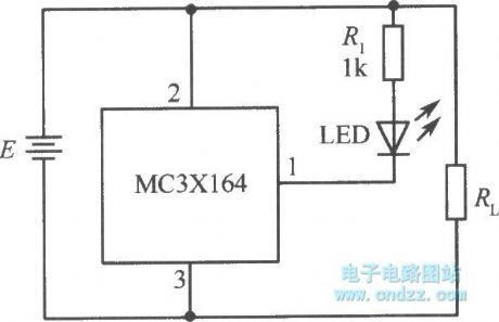
MC3X164 series typical application circuit
Published:2011/4/22 4:10:00 Author:Nicole | Keyword: typical application
View full Circuit Diagram | Comments | Reading(538)
Internal structure of UC3906
Published:2011/4/22 3:54:00 Author:Nicole | Keyword: internal structure
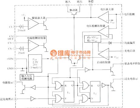
As VRLA battery charge special chip, UC3906 has 3 kinds of charging logic control and detection function to achieve the best charge of VRLA battery, it also has the functions of environmental temperature self-adapting, charge-discharge extent self-adapting, and current limiting, under-voltage protection. The adopted temperature compensation technology can make all kinds of charging transformational voltage change in relation to the VRLA battery voltage temperature coefficient, then the VRLA battery will reach the best charging state within a wide temperature range. The internal structure diagram is shown as below:
(View)
View full Circuit Diagram | Comments | Reading(1500)
TS28 circuit diagram
Published:2011/4/20 21:55:00 Author:Rebekka | Keyword: circuit diagram
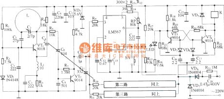
Remote working power outlet uses half-wave rectifier RC Buck. The receive part uses the regulator voltage tube regulator. Receiver circuit uses a simple super-regenerative circuit-type receiver circuit.
(View)
View full Circuit Diagram | Comments | Reading(585)
TC620 temperature sensing automatic heating temperature control circuit diagram
Published:2011/4/20 21:51:00 Author:Rebekka | Keyword: Temperature control , temperature sensing
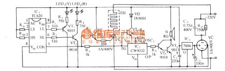
Circuit is shown as below. It includes TC620 temperature control circuit, the temperature indicating circuit, SCR control heating circuit, vocal music buck rectifier circuit and communication circuit. (View)
View full Circuit Diagram | Comments | Reading(818)
Infrared Ray Remote Control Fan Circuit
Published:2011/4/21 1:40:00 Author:Tina | Keyword: Infrared Ray, Remote Control, Fan Circuit
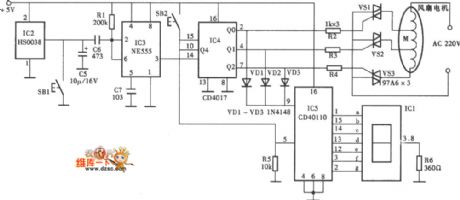
The Infrared Ray Remote Control Fan Circuit is as shown:
(View)
View full Circuit Diagram | Comments | Reading(2461)
KIA Electrical System Circuit
Published:2011/4/21 8:30:00 Author:Christina | Keyword: KIA, Electrical System
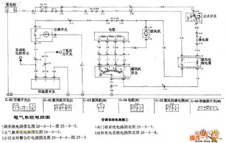
The KIA Electrical System Circuit is as shown. (View)
View full Circuit Diagram | Comments | Reading(675)
Overvoltage protection circuit with automatic reset
Published:2011/4/20 9:10:00 Author:Nicole | Keyword: overvoltage protection

The circuit mainly includes power supply, trigger start and control, to control load R1 turn on or off power supply through TRIAC ZN6346. Once the AC power voltage is too high, the ○A point's voltage on constant current component 1N5314 is rising, then the unidirectional SCR 2N5O6O turns on and transistor MPS6581 turns off, SCR 2N6239 turns off too, finally, main bi-directional SCR turns off, it can protect load from overvoltage damaging. (View)
View full Circuit Diagram | Comments | Reading(1208)
Polarity reversal boost power supply circuit diagram composed of LT1172
Published:2011/4/2 4:38:00 Author:Nicole | Keyword: boost power supply
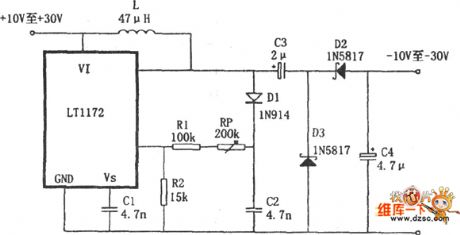
As shown, this is a polarity reversal boost power supply which is composed of boost switching regulator LT1172. The output voltage is -10 ~-30V, output current is 25mA, conversion efficiency is 80%. It uses the LT1172 to boost, and connect a charge pump which composed of C1, C2, D2, D3 on the output termination of LT1172, then to complete the output voltage polarity reversal.
(View)
View full Circuit Diagram | Comments | Reading(1865)
KIA Engine Circuit
Published:2011/4/21 9:15:00 Author:Christina | Keyword: KIA, Engine Circuit
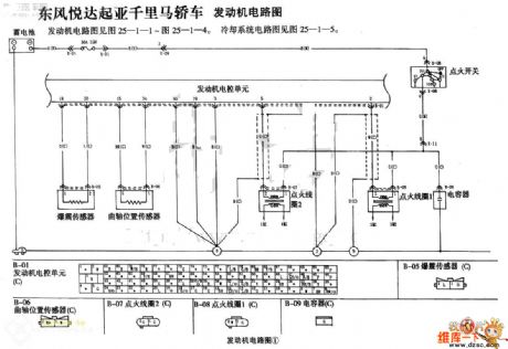
The KIA Engine Circuit is as shown. (View)
View full Circuit Diagram | Comments | Reading(670)
KIA Central Locking System Circuit
Published:2011/4/21 9:18:00 Author:Christina | Keyword: KIA, Central Locking System
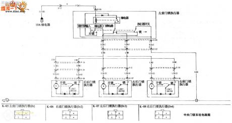
The KIA Central Locking System Circuit is as shown. (View)
View full Circuit Diagram | Comments | Reading(2589)
| Pages:2027/2234 At 2020212022202320242025202620272028202920302031203220332034203520362037203820392040Under 20 |
Circuit Categories
power supply circuit
Amplifier Circuit
Basic Circuit
LED and Light Circuit
Sensor Circuit
Signal Processing
Electrical Equipment Circuit
Control Circuit
Remote Control Circuit
A/D-D/A Converter Circuit
Audio Circuit
Measuring and Test Circuit
Communication Circuit
Computer-Related Circuit
555 Circuit
Automotive Circuit
Repairing Circuit