
Circuit Diagram
Index 2038
The interface circuit diagram between MT8880 and SCM
Published:2011/3/30 22:10:00 Author:Ecco | Keyword: interface circuit, SCM
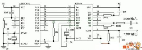
The interface circuit diagram between MT8880 and PLCis as below:
(View)
View full Circuit Diagram | Comments | Reading(2868)
The serial connecting circuit diagram between the RS232 and SCM
Published:2011/3/30 22:10:00 Author:Ecco | Keyword: serial connecting circuit
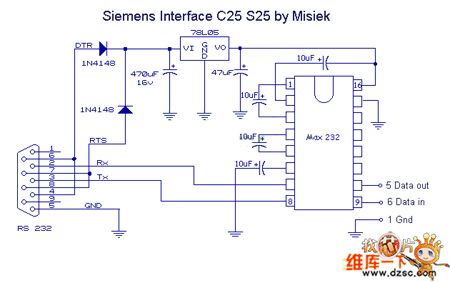
The serial connecting circuit diagram between the RS232 andSCM is as below:
(View)
View full Circuit Diagram | Comments | Reading(759)
The most simple and practical switching power supply circuit diagram
Published:2011/3/30 22:12:00 Author:Ecco | Keyword: most simple, most practical, switching
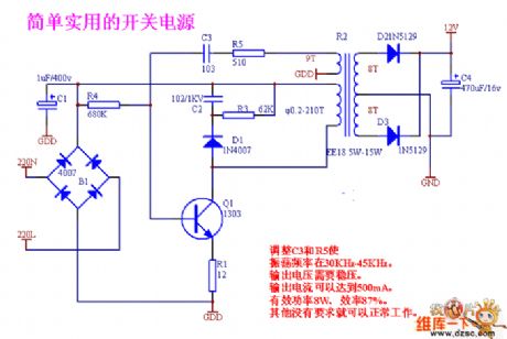
Simple switching supply circuit diagram with a triode:
(View)
View full Circuit Diagram | Comments | Reading(5902)
Simple hypnotic machine circuit diagram
Published:2011/3/30 22:29:00 Author:Ecco | Keyword: hypnotic machine
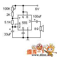
Time base circuit 555 constitutes a low frequncy oscillator, to output a short pulse to make the speaker delivery be similar to the sound of raindrop . The speaker adopts 2 inches, 8 ohms small scaled moving ring. The velocity of the raindrop voice can pass 100 K potential machine to regulate to a suitable extent. If raising one simple clock switch in power supply, then power supply can be cut off in time after the user enters dreamland.
(View)
View full Circuit Diagram | Comments | Reading(856)
High and stabilized voltage circuit diagram with photocoupler
Published:2011/3/30 22:48:00 Author:Ecco | Keyword: photocoupler, High voltage , stabilized voltage
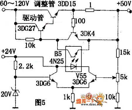
The circuitry is shown as chart. The drive tube need to adopt a transistor which can bear higher pressure(the drive tube is 3DG27). When output voltage enlarges, the bias of V55 raises, the forwarddirection current of the light-emitted diode in B5 will rise, and the voltage in the electrode of photosensitive tube minishes, the bias of regulator tube decreases while the internal resistance increses, then make the output voltage stable. (View)
View full Circuit Diagram | Comments | Reading(721)
Circuit of Multivibrator with D Trigger
Published:2011/4/20 21:52:00 Author:Sue | Keyword: Multivibrator, D Trigger

As seen in the figure, when RC component is connected to the Q output of D trigger, there is a mono-stable trigger. When RC is connected to the non-output of Q, there is an astable circuit, that is a multivibrator. (View)
View full Circuit Diagram | Comments | Reading(649)
Motor vehicle steering flasher 12
Published:2011/4/21 1:06:00 Author:Ecco | Keyword: Motor vehicle, steering flasher
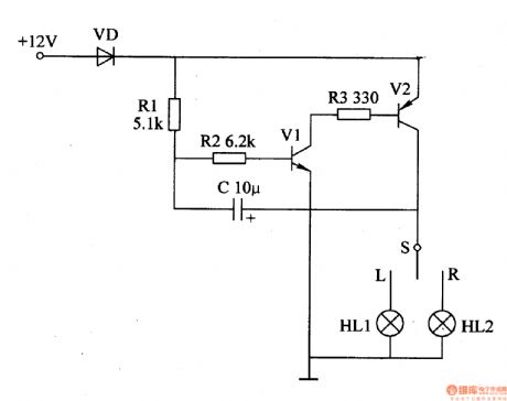
The motor vehicle steering flasher described in the example uses high-power transistors as electronic switches, the circuit is simple, easy to make.
The working principle
The motor vehicle steering flasher is composed of the flash circuit resistors R1-R3. Capacitor C, diode VD, transistors V1, V2, it is shown in Figure 7-21.
S is the vehicle turn signal switch; HLl and HL2 are the left turn signal and right turn signal respectively.
Before turning signal switch S (in the center), the oscillator circuit composed of vl, v2, and external RC components does not work. Placing S in the L or R position, the oscillation circuit works, V2 makes intermittent conduction with a certain frequency , Ll or HL2 is flashing.
Component selection
RI-R3 selects 1/4W carbon film resistor or metal film resistors.
C uses 25V electrolytic capacitors.
VD uses lN5402 silicon rectifier diode.
VI selects 3DGl2 or S8050 silicon NPN transistor; V2 uses 3AD30 germanium PNP transistors.
(View)
View full Circuit Diagram | Comments | Reading(2058)
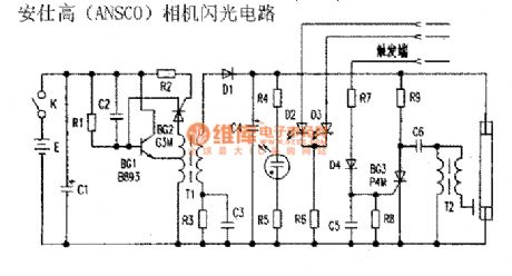
Ansco camera flash circuit
Published:2011/4/21 1:05:00 Author:Nicole | Keyword: Ansco, camera
View full Circuit Diagram | Comments | Reading(1373)
Circuit Of 555 Car Search Device
Published:2011/4/21 3:43:00 Author:TaoXi | Keyword: Car Search, Car Search Device, 555 Car Search Device
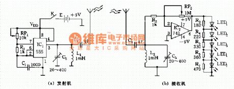
As shown, car search device composed of two parts, the transmitter and receiver. The transmitter is a medium wave frequency oscillaor with 555 as the core, the oscillator frequency should be selected lower than 535KHz, The value of frequency is decided by R1, RP1, C1 (F=1.44/(RP1+2R1)C1, L1, C2 form the output resonant circuit), then launch out by the antenna. Receiving circuit is composed of the input frequency selection network and the 741 op amplifier, magnification of the amplifier is decided by the ratio of RP2/R2. The LED1 ~ LED5 can be used to indicate the strength of the received signal, with the strengthening of the signal, LED will light one by one.
(View)
View full Circuit Diagram | Comments | Reading(1279)
Circuit Of LED Digital Voice Timekeeping Clock
Published:2011/4/21 3:42:00 Author:TaoXi | Keyword: LED, Digital Voice Timekeeping
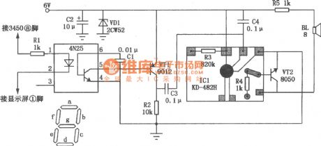
General dynamics LED digital clock does not have the timekeeping function, but we only need to add a simple circuit to make it achieve the function of whole point timekeeping. This circuit has the programmable mute function, it will not alarm from 23:00 to 5:00. So it will not affect our sweety dream. The circuit is as shown. The signal of whole point timekeeping comes from the 8-pin of LED digital clock IC 3450 or 8560, this pin is the output-b-segment of the common cathode display. When the number is 0 to 4, b-segment is high level 1 , only when the number is 5, the level is 0 . So that when the time advanced from 59 minutes to 00 minutes, the potential changes from 0 to 1. This signal is limited by the resistor Rl, the 4N25 optocoupler will isolate coupling, transistor VT1 enlarge the signal and at last speaker BL will issue the chime sound. (View)
View full Circuit Diagram | Comments | Reading(1749)
Schematic Of DF Data Transmission Module And Super-regenerative Receiver Module
Published:2011/4/20 21:59:00 Author:TaoXi | Keyword: DF Data Transmission Module, Super-regenerative Receiver Module
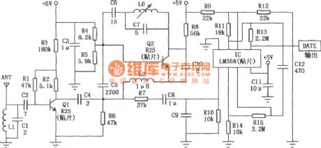
The operating frequency of the DF data transmission module is 315MHz, with the technology of surface acoustic wave resonator frequency stabilization, this module has great high frequency-stability. When the ambient temperature is between -25℃ to +85℃, the frequency drift is only 3×10⁻⁶ /℃, so this module is particularly suitable for multiple-transmit & single-receive wireless remote control and data transmission systems. Wireless data transmission technology is widely used in industrial data acquisition system, mini-wireless data terminal, vehicle monitoring, remote control, telemetry, access control systems, paging area, identification, RF contactless smart card, security, fire protection systems.
The equivalent circuit of the DF data transmission module:
DF receiver module circuit:
(View)
View full Circuit Diagram | Comments | Reading(5223)
Rising Edge Triggered High-current Switch Composed of MIC5156-××
Published:2011/4/20 21:58:00 Author:TaoXi | Keyword: Rising Edge, Triggered High-current Switch
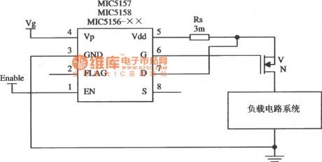
The Rising Edge Triggered High-current Switch Composed of MIC5156-×× (View)
View full Circuit Diagram | Comments | Reading(905)
3.3 V/lOA Output Linear Regulator Circuit Composed of MIC5157
Published:2011/4/21 2:31:00 Author:TaoXi | Keyword: 3.3V/lOA, Output Linear Regulator
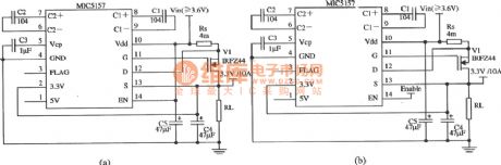
The 3.3 V/lOA Output Linear Regulator Circuit Composed of MIC5157
(View)
View full Circuit Diagram | Comments | Reading(897)
Circuit Of Electronic Megaphone
Published:2011/4/21 2:39:00 Author:TaoXi | Keyword: Electronic Megaphone
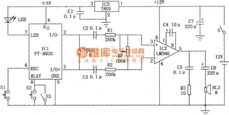
The circuit of electronic megaphone is as shown, it composed of three parts: voice recording, audio power amplifier and power supply. The ICl is the fool type of voice recording IC (PT-8815/20/30), it has the function of 30 seconds voice recording and 30 seconds playback; IC2 is the integrated power amplifier (LM386) and used to amplify the output voice signal of ICl, and IC2helps the speaker to get enough power to send out the voice; IC3 uses the 7805-type three-terminal integrated voltage stabilizer. (View)
View full Circuit Diagram | Comments | Reading(3326)
(CD4017、RCM1) Radio Control Light Switch Circuit
Published:2011/4/21 2:21:00 Author:TaoXi | Keyword: Radio Control, Light Switch
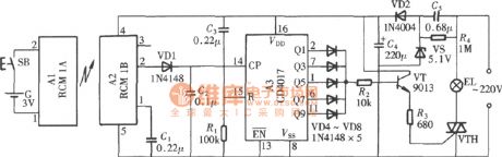
(CD4017、RCM1) Radio Control Light Switch Circuit
(View)
View full Circuit Diagram | Comments | Reading(1178)
The Circuit Of Dual Power Switch Of The CD4069
Published:2011/4/21 2:24:00 Author:TaoXi | Keyword: Dual Power Switch, Single-button Control
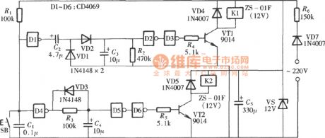
The Circuit of dual power switch that compose Of the CD4069
(View)
View full Circuit Diagram | Comments | Reading(919)
The Pin Functions and Data Circuit of the TDA9178
Published:2011/4/21 2:30:00 Author:TaoXi | Keyword: Pin Functions, Data Circuit
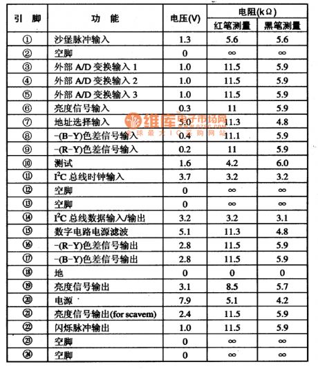
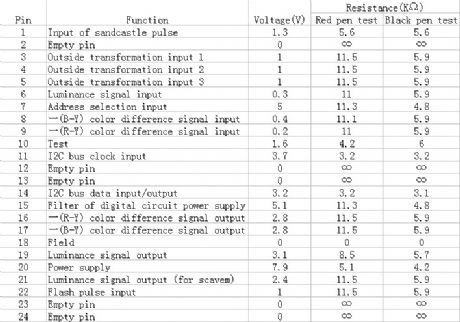
1. Pin functions and data: with the package of 24-pin dual in-line, the pin functions and data circuit of the TDA9178 is listed in the table 64.
Table 64 The pin functions and data circuit of the TDA9178
(View)
View full Circuit Diagram | Comments | Reading(592)
Ni-Cd storage battery with 6v12v/2A automatical charging equipment
Published:2011/4/21 1:20:00 Author:Nicole | Keyword: Ni-Cd storage battery, charging equipment
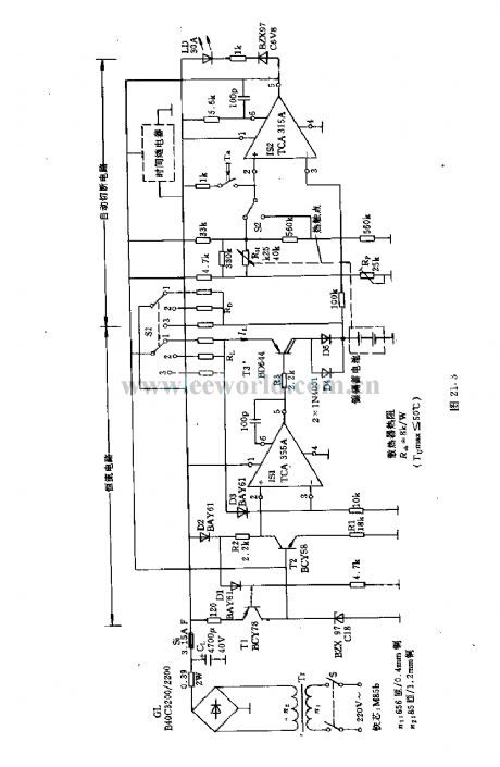
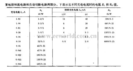
This automatical charging equipment can ensure the storage battery has a good process of charging, it also can prevent overload. It has three charging methods: standard charging, sustainable(microflow )charging and fast charging, they have differences in charging current and cuting the process of charging.
(View)
View full Circuit Diagram | Comments | Reading(692)
Calendar clock circuit
Published:2011/4/21 1:33:00 Author:Nicole | Keyword: calendar, clock

FCM CT7001 clock chip is produced by Fairchild, it can make 7 paragraphs LED of 6 bits display 12h or 24h, and it also has the functions of 28/30/31 calendar and alarm clock. ③, ⑤, ⑩, (12) of SN75491 driver chip are connected to (11) by a 150Ω resistance. Usually, RL is 2.7kΩ, it can limit the LED current below 5mA. (View)
View full Circuit Diagram | Comments | Reading(1392)
The Circuit Of MIC5158 High-speed Rising Redge Triggered Switch
Published:2011/4/20 21:56:00 Author:TaoXi | Keyword: High-speed, Rising Redge Triggered
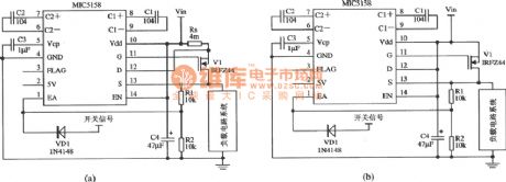
The Circuit Of MIC5158 High-speed Rising Redge Triggered Switch
(View)
View full Circuit Diagram | Comments | Reading(549)
| Pages:2038/2234 At 2020212022202320242025202620272028202920302031203220332034203520362037203820392040Under 20 |
Circuit Categories
power supply circuit
Amplifier Circuit
Basic Circuit
LED and Light Circuit
Sensor Circuit
Signal Processing
Electrical Equipment Circuit
Control Circuit
Remote Control Circuit
A/D-D/A Converter Circuit
Audio Circuit
Measuring and Test Circuit
Communication Circuit
Computer-Related Circuit
555 Circuit
Automotive Circuit
Repairing Circuit