
Circuit Diagram
Index 2030
Raindrops Sound Generator Circuit Composed of NE555
Published:2011/4/21 21:50:00 Author:Sue | Keyword: Raindrops Sound, Generator
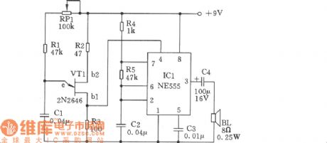
The circuit is very simple and can be made by ordinary components. It has two oscillators, one of which is variable low frequency oscillator with unijunction transistor VT1(2N2646). The transistor can achieve oscillation without resonance coils. (View)
View full Circuit Diagram | Comments | Reading(1409)
Simplified Wave Sound Generator Circuit
Published:2011/4/21 21:54:00 Author:Sue | Keyword: Simplified, Wave Sound, Generator
View full Circuit Diagram | Comments | Reading(612)
Sound Generator Circuit Composed of CH4040
Published:2011/4/21 22:39:00 Author:Sue | Keyword: Sound, Generator

View full Circuit Diagram | Comments | Reading(538)
Electric Shock Warning Device Circuit
Published:2011/4/21 7:53:00 Author:Christina | Keyword: Electric Shock, Warning Device
The Electric Shock Warning Device Circuit is as shown:
(View)
View full Circuit Diagram | Comments | Reading(1087)
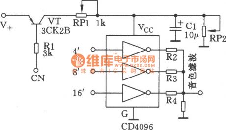
Multi-Functional Sound Generator Circuit Composed of NE555 and CC4051
Published:2011/4/21 22:53:00 Author:Sue | Keyword: Multi-Functional, Sound, Generator
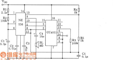
This circuit is used as sound generator in timer alarms and electronic toys. Its features are as follows. The adaptive supply voltage range is large, that is to say it can work under voltage ranging from 4V to 18V. And the tones and tempos will not change with supply voltage, which can be used to indicate all kinds of states. (View)
View full Circuit Diagram | Comments | Reading(653)
Envelope Generator Circuit of Digital Electronic Organ
Published:2011/4/21 23:04:00 Author:Sue | Keyword: Envelope, Generator, Digital, Electronic Organ
View full Circuit Diagram | Comments | Reading(918)
Improved TOP222P switching power supply module
Published:2011/4/21 5:51:00 Author:May | Keyword: Improved, switching, power supply module
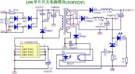
The AC input voltage of small switching power supply module using TOP222P chip is 100~245V. And it is two ways DC output. The largest DC output is 10v800mA(15v800mA)、5v800mA, the total output is less than 15W, power supply efficiency is 6%~85%. (Note 1: the output 5V group of this power module has the function of voltage regulation, another group output voltage can set like: it is 15V when connected with + , it is 10V when connected with 0 ).voltage accuracy: 4%;votlage adjustment rate: 0.7%;5V load adjustment rate: 1%;10V load adjustment rate: 8%;or 15V load adjustment rate: 10%;The size of small power supply module: length is 46mm, width is 28mm, height is 20mm.parts lists of small power supply module name quantityTOP222P chip 1EE19 transformer 1UF4007diode 1PC817 opto-coupler 13.3UH bead 23.6 voltage regulator diode 1471 voltage dependent resistor 110UF/400V electrolysis 1102/1KV ceramic chip 1470UF/25V electrolysis 1470UF/25V electrolysis 147UF/25V electrolysis 1100UF/25V electrolysis 1UF4004 diode 2IN4148 diode 1(can replace by UF4004 diode)1N4007diode 433/1W resistor 156K/0.25W resistor 110/0.25W resistor 1100/0.25W resistor 11K/0.25W resistor 13mmLED 1circuit wafer 1 (View)
View full Circuit Diagram | Comments | Reading(4118)
Multivibrator Circuit Composed of 555 with Adjustable Duty Cycle
Published:2011/4/21 23:11:00 Author:Sue | Keyword: Multivibrator, Adjustable, Duty Cycle
View full Circuit Diagram | Comments | Reading(578)
Wien Bridge and Its Oscillation Circuit
Published:2011/4/21 23:17:00 Author:Sue | Keyword: Wien Bridge, Oscillation
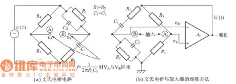
(a) Wien Bridge Circuit
(b) Method of connecting Wien Bridge with amplifier. (View)
View full Circuit Diagram | Comments | Reading(540)
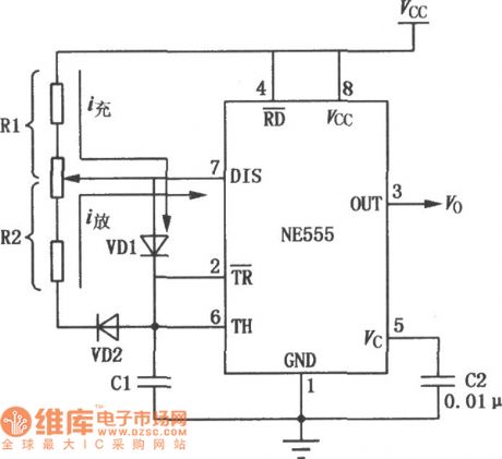
Pulse Battery Charger Circuit
Published:2011/4/21 7:02:00 Author:Christina | Keyword: Pulse, Battery Charger
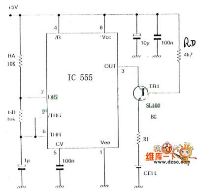
The Pulse Battery Charger Circuit is as shown:
(View)
View full Circuit Diagram | Comments | Reading(2471)
Remote Control Switch Circuit
Published:2011/4/21 7:00:00 Author:Christina | Keyword: Remote Control, Switch Circuit
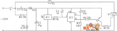
The Remote Control Switch Circuit is as shown:
(View)
View full Circuit Diagram | Comments | Reading(1015)
Circuit Of Infrared Ray Remote Control To Discolor
Published:2011/4/21 6:27:00 Author:Christina | Keyword: Infrared Ray, Remote Control
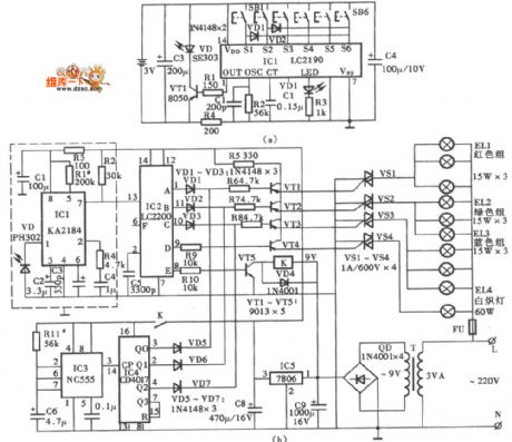
The Circuit Of Infrared Ray Remote Control To Discolor is as shown:
(View)
View full Circuit Diagram | Comments | Reading(847)
SCR Dimmer Circuit Of The 120V Incandescent Lamp
Published:2011/4/21 6:18:00 Author:Christina | Keyword: SCR Dimmer, 120V Incandescent Lamp
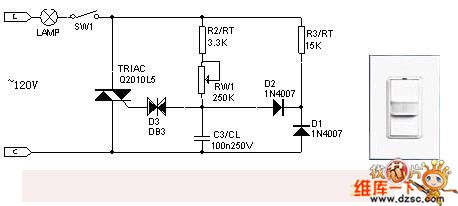
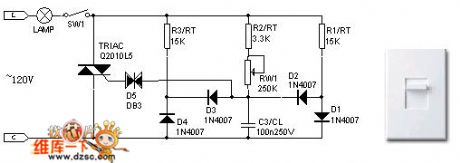
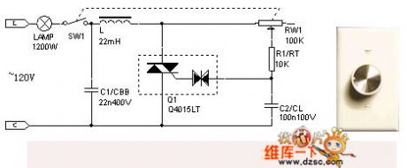
Typical 120v SCR Dimmer
Another Kind Of 120v SCR Dimmer
120v SCR Dimmer With The Composite Device (View)
View full Circuit Diagram | Comments | Reading(3984)
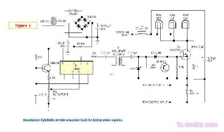
Common power supply load circuit with bulb
Published:2011/4/22 2:29:00 Author:Nicole | Keyword: power supply load, bulb
View full Circuit Diagram | Comments | Reading(700)
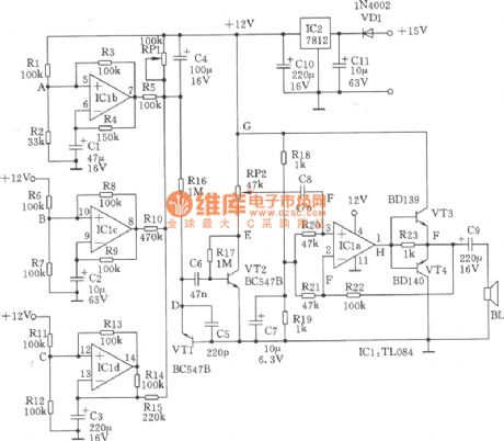
Storehouse humidity detection and automatic ventilating air exhausting device circuit(MS01-A)
Published:2011/4/20 20:54:00 Author:Nicole | Keyword: storehouse, humidity detection, automatic ventilating, air exhausting device

The circuit is as shown, it is composed of precise time base oscillator, D trigger, temperature detection circuit, comparison circuit, relay control ventilating circuit, language admonishment circuit and AC depressurization rectifier circuit. BC adopts the crystal in silica watch, its natural frequency is 32768Hz; K1 adopts JZC-22F; C6, C7 adopt CD11-16V electrolytic capacitor; R10 adopts RJ-2W-820kΩ, RP1 adopts WH5 synthetic film potentiometer, the other resistances all adopt RT-1/8W carbon-film potentiometer; C8 uses CBB-400V-0.75μF; VC uses 1A/400V full bridge rectifier module or four 1N4004 to build a bridge rectifier; B uses 0.25W(8Ω) electricity-powered loudspeaker. (View)
View full Circuit Diagram | Comments | Reading(932)
+5V 4W switching power supply circuit composed of single chip TOP210
Published:2011/4/21 2:21:00 Author:May | Keyword: +5V 4W, switching power supply
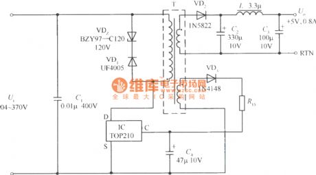
+5V 4W switching power supply circuit composed of single chip TOP210 is shown in the diagram. DC input voltage Ui is got after 85~265V AC rectifying and filtering. The voltage adjustment rate of this switching power supply is Sv=±1.5% (input DC voltage is 104~370V), load adjustment rate Si=±5% (load current changes from 10% to 100%), output ripples voltage is ±25mV. When the lead wire of Ui and TOP210 is shorter, it also can save IC. Clamping protection circuit consists of VDz and VD1. After the secondary voltage rectifying and filtering by VD2, C2, L and C3, it can get +5V, 0.8A output. Feed back winding first rectifying by VD3, than it is smoothed filtering by R and C4 and offer control end current to TOP210.
(View)
View full Circuit Diagram | Comments | Reading(3118)
Timing flashing circuit using FET drive
Published:2011/4/20 21:46:00 Author:Nicole | Keyword: Timing flashing, FET drive

The circuit is as shown, it can form a timing control circuit of cycle light which only needs a few components. This circuit is composed of MOS time base circuit 7555, CMOS decimal counter (pulse distributor) 4017 and last stage VMOS power transistor. The power transistor can control the bulb with 2A maximum current. Resistance Rv between bulb and power supply +UB is used to limit connection current.
The frequency of time base circuit is adjusted by potentiometer RP(it is about 0.5~10Hz). Nine-stage circulation register passes clock input terminal then controlled by square wave output singal, to change each output terminal into high level. Because pin 11 is connected to reduction input terminal pin 15, so the coming tenth pulse will control the first light to turn on. (View)
View full Circuit Diagram | Comments | Reading(710)
Four-syllable circuit
Published:2011/4/21 22:09:00 Author:Nicole | Keyword: four-syllable
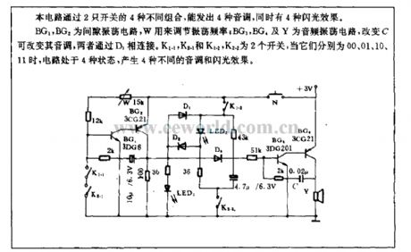
With four different groups of 2 switches, this circuit can send out 4 tones, and 4 flashing effects.
BG1, BG2 are gap oscillation circuit, W is used to adjust oscillation frequency; BG3, BG4 and Y are audio oscillation circuit, if C changes, the tone can be changed, they are connected by D3. K1-1, K2-1 and K1-2, K2-2 are two switches, when they are 00, 01, 10, 11, the circuit is in four states, and it will produce 4 kinds of tone and flashing effects. (View)
View full Circuit Diagram | Comments | Reading(788)
Common inverter principle diagram on the market(12VDC to 220VAC 150W)
Published:2011/4/22 1:55:00 Author:Nicole | Keyword: inverter
View full Circuit Diagram | Comments | Reading(2522)
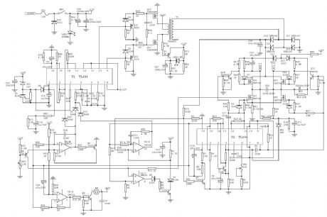
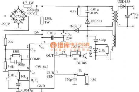
Single end fly back converter circuit external connected ambipolar power tube by CWI842
Published:2011/4/20 22:29:00 Author:May | Keyword: Single end, fly back, converter, ambipolar power tube
View full Circuit Diagram | Comments | Reading(570)
| Pages:2030/2234 At 2020212022202320242025202620272028202920302031203220332034203520362037203820392040Under 20 |
Circuit Categories
power supply circuit
Amplifier Circuit
Basic Circuit
LED and Light Circuit
Sensor Circuit
Signal Processing
Electrical Equipment Circuit
Control Circuit
Remote Control Circuit
A/D-D/A Converter Circuit
Audio Circuit
Measuring and Test Circuit
Communication Circuit
Computer-Related Circuit
555 Circuit
Automotive Circuit
Repairing Circuit