
Circuit Diagram
Index 2031
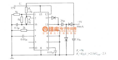
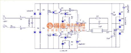
Buck chopped wave switching regulated power supply circuit composed of CW1524
Published:2011/4/20 22:26:00 Author:May | Keyword: Buck, chopped wave switching, regulated power supply
View full Circuit Diagram | Comments | Reading(521)
Like polarity drive circuit
Published:2011/4/21 22:49:00 Author:Nicole | Keyword: like polarity
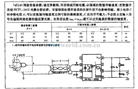
Using shield wire, twisted pair or coaxial cable, the 74S140 like polarity driver transports the data to HCPL-2602 optical coupling receiver with high data transmission speed. The reflex action produced by active terminal receiver has no influence on the performance. To connect capacitance C and in series with resistance R, it can make the data transmission speed reach the possible maximum speed. C should as large as possible, it is no need to prevent the regulator tube of receiver from turning off during the input singal negative bias. If tPHL=tPLH, then it will obtain the maximum data transmission speed. (View)
View full Circuit Diagram | Comments | Reading(579)
On/off control circuit
Published:2011/4/22 1:15:00 Author:Nicole | Keyword: On/off control

CA3062 combined photodetector and power amplifier can produce on/off output by optical signal. The output transistor of IC should be saturated or closed, prevent the temperature from rising. When the light of IR LED falls on the optical input terminal of IC, complementary output can select the load which is normal open or normal off. After blocking the light path, it will produceopposite load situation. (View)
View full Circuit Diagram | Comments | Reading(577)
Digital control constant current source
Published:2011/4/22 0:22:00 Author:Nicole | Keyword: Digital control, constant current source
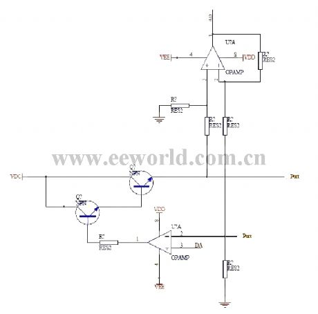
This digital control constant current source is designed for charging to storage battery. D/A converter outputs a voltage value to the in-phase terminal of below operational amplifier, the current I=Uad/ sampling resistance, two PORT is used to connect the +, - polar of storage battery. The above operational amplifier is connected into a amplifier circuit with 1/4 amplification. It is used to test the storage battery voltage. In figure, the two regulator are 3dd13 and 3dd15. (View)
View full Circuit Diagram | Comments | Reading(1833)
Input state indication circuit
Published:2011/4/22 1:30:00 Author:Nicole | Keyword: Input state indication
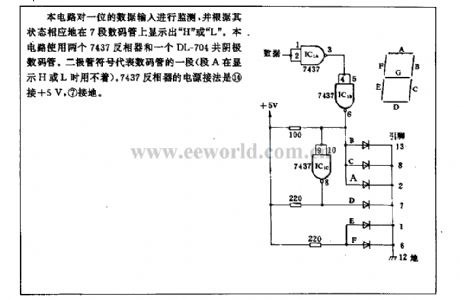
This circuit keeps an eye on a bit data input, and it will display H or L on the 7-phase LED according to its state. The circuit uses two 7437 inverters and a DL-704 common catthode LED. The diode symbol represents a phase LED(A phase is not needed when it display H or L). The power supply connection way of 7437 inverter: (14) connects to +5V, ⑦ connects to ground. (View)
View full Circuit Diagram | Comments | Reading(565)
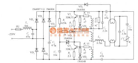
40W fluorescent light electron ballast electrical schematic diagram
Published:2011/4/21 4:07:00 Author:May | Keyword: 40W, fluorescent light, electron ballast
View full Circuit Diagram | Comments | Reading(2683)
EW-8W electron ballast
Published:2011/4/21 4:04:00 Author:May | Keyword: electron ballast

View full Circuit Diagram | Comments | Reading(621)
IR21571 straight tube type integrated circuit electron ballast
Published:2011/4/21 3:52:00 Author:May | Keyword: straight tube type, integrated circuit, electron ballast

IR21571 is designed for straight tube type ballast in specialty. It sums up various kinds functions of IR2156 and add new protection function of miss match and under voltage. (View)
View full Circuit Diagram | Comments | Reading(725)
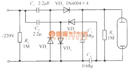
Voltage multiplying rectifier electron ballast circuit
Published:2011/4/21 3:46:00 Author:May | Keyword: Voltage multiplying rectifier, electron ballast
View full Circuit Diagram | Comments | Reading(1033)
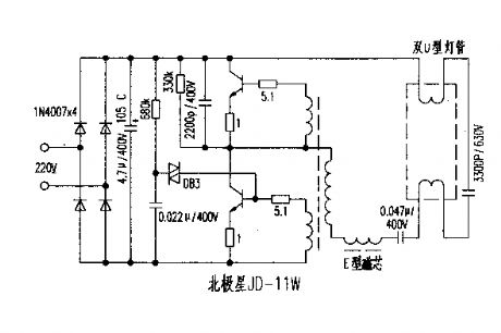
North Star JD-11W electron ballast circuit
Published:2011/4/21 3:43:00 Author:May | Keyword: North Star, electron ballast
View full Circuit Diagram | Comments | Reading(745)
Low cost high power factor electron ballast circuit
Published:2011/4/21 3:42:00 Author:May | Keyword: Low cost, high power factor, electron ballast
View full Circuit Diagram | Comments | Reading(700)
74 series digital circuit 74165 74LS165 and other eight bits shift register (serial-in complementation parallel-out)
Published:2011/4/21 6:04:00 Author:May | Keyword: digital, eight bits, shift register, serial-in complementation parallel-out

View full Circuit Diagram | Comments | Reading(3697)
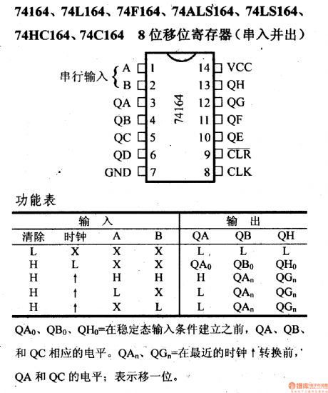
74 series digital circuit 74164 74L164 and other eight bits shift register (serial-in-parallel-out)
Published:2011/4/21 6:02:00 Author:May | Keyword: digital, eight bits, shift register, serial-in-parallel-out
View full Circuit Diagram | Comments | Reading(4572)
Precise Bridge Isolation Amplifier Circuit
Published:2011/4/22 0:23:00 Author:Joyce | Keyword: Precise, Bridge, Isolation Amplifier
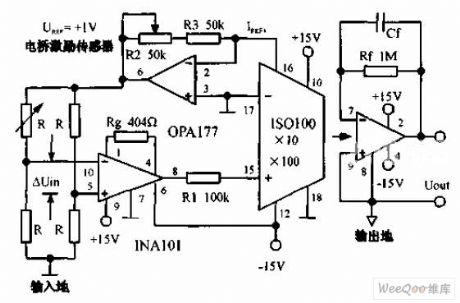
Precise bridge isolation amplifier circuit is shown in the chart below.0 ~10mV unipolarity signal outputed by bridge would be enlarged by 100 times by high precision instrument amplifier INA101 ,and then be enlargend in a unipolarity isolated way by optical coupling linear isolation amplifier ISO100 . Output of INA101 must be less than the negative value of minus 2mV. The gain of isolation amplifier is 10 ,and the total gain is 1000. Both sides of the amplifier are supplied with two groups of (plus or minus) 15V power. (View)
View full Circuit Diagram | Comments | Reading(1044)
SGMW Chevrolet(Spark)saloon car automatic transmission circuit diagram
Published:2011/4/21 21:41:00 Author:muriel | Keyword: SGMW Chevrolet(Spark), saloon car, automatic transmission
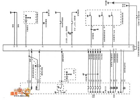
SGMW Chevrolet(Spark)saloon car automatic transmission circuit diagram
(View)
View full Circuit Diagram | Comments | Reading(1822)
SHANGHAI GM Chevrolet(Epica)saloon car data transmission bus circuit diagram
Published:2011/4/21 21:37:00 Author:muriel | Keyword: SHANGHAI GM Chevrolet(Epica), saloon car , data transmission bus
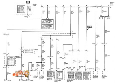
SHANGHAI GM Chevrolet(Epica)saloon car data transmission bus circuit diagram
(View)
View full Circuit Diagram | Comments | Reading(612)
SHANGHAI GM BUICK(Royaum) saloon car vehicle control module circuit diagram(eight)
Published:2011/4/21 21:24:00 Author:muriel | Keyword: SHANGHAI GM BUICK(Royaum) , saloon car, vehicle control module
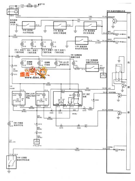
Figure SHANGHAI GM BUICK(Royaum) saloon car vehicle control module circuit diagram(eight)--dome light gate control switch-2 level and 3 level (View)
View full Circuit Diagram | Comments | Reading(466)
SHANGHAI GM BUICK(Royaum) saloon car vehicle control module circuit diagram(seven)
Published:2011/4/21 21:23:00 Author:muriel | Keyword: SHANGHAI GM BUICK(Royaum), saloon car , vehicle control module
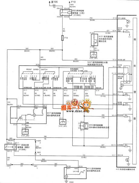
Figure SHANGHAI GM BUICK(Royaum) saloon car vehicle control module circuit diagram(seven)--dome light gate control switch-1 level (View)
View full Circuit Diagram | Comments | Reading(501)
SHANGHAI GM BUICK(Royaum) saloon car vehicle control module circuit diagram(five)
Published:2011/4/21 21:25:00 Author:muriel | Keyword: SHANGHAI GM BUICK(Royaum), saloon car, vehicle control module
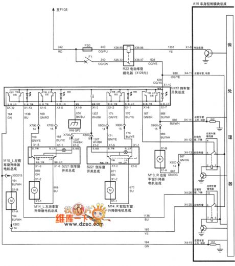
Figure SHANGHAI GM BUICK(Royaum) saloon car vehicle control module circuit diagram(five)--power sunroof (View)
View full Circuit Diagram | Comments | Reading(523)
SHANGHAI GM BUICK(Royaum) saloon car vehicle control module circuit diagram(four)
Published:2011/4/21 21:29:00 Author:muriel | Keyword: SHANGHAI GM BUICK(Royaum), saloon car , vehicle control module
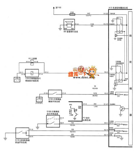
Figure SHANGHAI GM BUICK(Royaum) saloon car vehicle control module circuit diagram(four)--Invasion warning system andtrunk lid solenoid valve (View)
View full Circuit Diagram | Comments | Reading(508)
| Pages:2031/2234 At 2020212022202320242025202620272028202920302031203220332034203520362037203820392040Under 20 |
Circuit Categories
power supply circuit
Amplifier Circuit
Basic Circuit
LED and Light Circuit
Sensor Circuit
Signal Processing
Electrical Equipment Circuit
Control Circuit
Remote Control Circuit
A/D-D/A Converter Circuit
Audio Circuit
Measuring and Test Circuit
Communication Circuit
Computer-Related Circuit
555 Circuit
Automotive Circuit
Repairing Circuit