
Circuit Diagram
Index 2040
E-AV Conversion Switch Circuit
Published:2011/4/20 22:33:00 Author:TaoXi | Keyword: E-AV, Conversion Switch
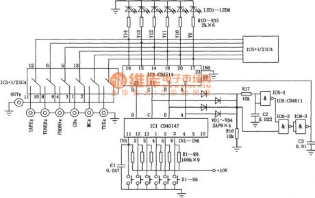
E-AV Conversion Switch Circuit
(View)
View full Circuit Diagram | Comments | Reading(921)
Circuit Diagram of TX05D Infrared Remote Control Light
Published:2011/4/21 1:21:00 Author:Tina | Keyword: Infrared, Remote Control
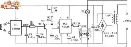
The Circuit Diagram of TX05D Infrared Remote Control Light is as shown.
(View)
View full Circuit Diagram | Comments | Reading(1557)
Circuit Of Symmetry Amplifier
Published:2011/4/20 18:52:00 Author: | Keyword: Symmetry
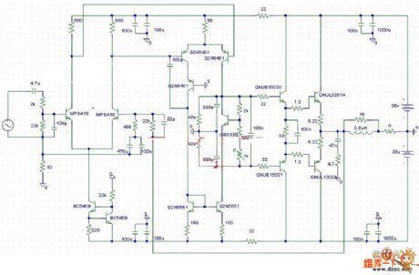
The Circuit Of Symmetry Amplifier is as shown.
Welcome to reprint, the information is from the Weiku Electronic Market Network (www.dzsc.com). (View)
View full Circuit Diagram | Comments | Reading(903)
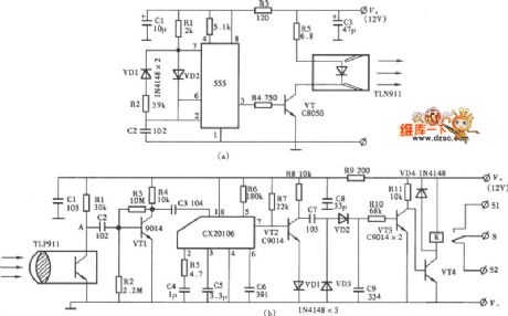
Circuit Diagram of KA2184 Infrared Ray Remote Control Light
Published:2011/4/21 1:23:00 Author:Tina | Keyword: Infrared Ray, Remote Control

The Circuit Diagram of KA2184 Infrared Ray Remote Control Light. (a) Circuit Diagram; (b) installation diagram is as shown:
(View)
View full Circuit Diagram | Comments | Reading(1385)
Long-range Infrared Ray Remote Circuit
Published:2011/4/21 1:00:00 Author:Tina | Keyword: Long-range, Infrared Ray, Remote Circuit
The Long-range Infrared Ray Remote Circuit is as shown:
(View)
View full Circuit Diagram | Comments | Reading(1433)
Relay circuit with delay pull-in and delay release
Published:2011/4/19 6:19:00 Author:Nicole | Keyword: relay, delay pull-in, delay release
The circuit adopts single transistor circuit can achieve independent adjust delay pull-in and delay turn-off time, the circuit consists of a relay A with auxiliary contact a. After pressing switch S, capacitance C charges firstly, using potentiometer R2 can adjust pull-in time. After relay pull-in, auxiliary contact a connects resistance R5 and potentiometer R3 to transistor base, after switch S off, the ralay release time is determined by R3. (View)
View full Circuit Diagram | Comments | Reading(566)
LG8150 touch stepping dimming light circuit
Published:2011/4/19 6:49:00 Author:Nicole | Keyword: dimming light
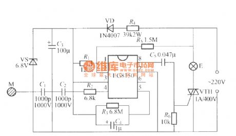
The figure is as shown, it adopts touch stepping dimming light of LG8150 integrated circuit, the finger touches M at a time, the brightness of bulb E is low brightness, middle brightness, most brightness, turn-off, low brightness... cyclic change, this circuit is suit for producing dimming table lamp. (View)
View full Circuit Diagram | Comments | Reading(864)
Typical application circuit of audio synchronous color lamp control integrated circuit 5G052
Published:2011/4/18 10:06:00 Author:Nicole | Keyword: audio, color lamp
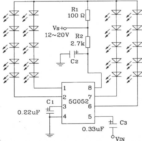
The sequence of 5G052 four-way output is A, B, C, D, the lowest work voltage VDD is 5V, but when the VDD declines, LED fluorescence change rate will rise, compared to power supply, the oscillation frequency fosc is unstable. In figure, the range of oscillation frequency is decided by C1, that is the variation range of fluorescence rate. If C1 increases, the parallel connecting resistance on C1 will improve the rate. C2 is power decoupling capacitor. R1 is LED current resistance. R2 is power supply current limiting. (View)
View full Circuit Diagram | Comments | Reading(522)
White backlight application plan circuit of a telephone PDA
Published:2011/4/20 9:13:00 Author:Nicole | Keyword: White backlight, telephone
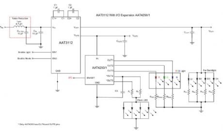
AAT3112 contains drive white backlight, flashing light and RGB tri-color light. In this application, using VOUT1 output of AAT3112 as backlight output, VOUT2 connects to the I/O expansion chip AAT4290/1 of AnalogicTechTM, it is used as RGB light control and flashing light control. Using AnalogicTechTM’s S2Cwire control technique to control the voltage output of OUT1~OUT5. OUT1~OUT5 output can control the R、G、B lights, the OUT4 and OUT5 of AAT4290 is used to control the flashing light and flashlight mode output. (View)
View full Circuit Diagram | Comments | Reading(610)
Lossless LED drive circuit with 24V power supply
Published:2011/4/19 6:44:00 Author:Nicole | Keyword: LED drive, 24V power supply
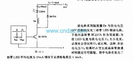
This circuit adopts LED drive circuit,its choke Dr is matched with 24V power voltage. Using under transistor BC237A as constant current source, in order to let LED current has no relationship with power voltage Us, so the duty tatio should be proportionate to Us. Thus, when the power voltage Us is higher, the duty ratio or the turn on time of transistor will short. In this circuit, in the condition of LED average current is 20mA, the total consumption current is only 3.4mA. (View)
View full Circuit Diagram | Comments | Reading(1207)
25Ω loundspeaker overload protection circuit
Published:2011/4/20 22:35:00 Author:Nicole | Keyword: 25Ω loundspeaker, overload protection
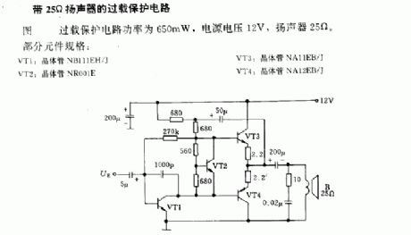
In figure, the overload protection circuit power is 650mW, the power voltage is 12V, the loundspeaker is 25Ω.
Some components' standard: VT1: transistor NB111EH/J; VT2: transistor NR001E; VT3: transistor NA11EB/J; VT4: transistor NA12EB/J. (View)
View full Circuit Diagram | Comments | Reading(552)
Light switch circuit with luminous indication
Published:2011/4/19 6:42:00 Author:Nicole | Keyword: Light switch, luminous indication
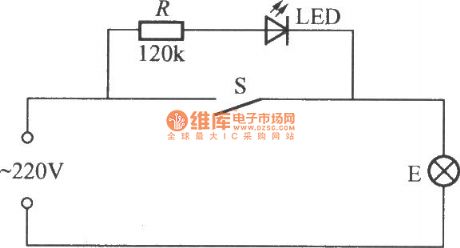
The light switch circuit with luminous indication is as shown, when the switch S is turned on , 220V AC power supply is pressure released and current limited by resistance R, then it is added to the two sides of LED with bulb E, making LED conduction and lighting, it is convenient to find the switch at night. The current flows E is tiny, it is only about 2mA, this can be considered there is no power consumption, the light is off too. To close S, bulb E can work normally, but LED turns off. To open S, LED does not light, if the filament of bulb E is not burned out, then it must be power failure. (View)
View full Circuit Diagram | Comments | Reading(1698)
Intermittent timer circuit composed of two RS6445C long time timing integrated circuit
Published:2011/4/19 4:44:00 Author:Nicole | Keyword: timer, long time timing
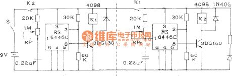
This circuit can control equipments intermittent work. In figure, 4, 5 feet are grouding, the preset level are all low level L, potentiometer RP1 and RP2 is used to adjust the working time and stopping time, both can continuous adjust in 0.5~24 hours. If it is needed to decrease the timing time, you can increase the potentiometer resistance. If it is divided into two according to the dashed line in figure, then it will to be two separate timers. (View)
View full Circuit Diagram | Comments | Reading(845)
Delay light circuit with time base circuit
Published:2011/4/20 23:01:00 Author:Nicole | Keyword: Delay light, time base
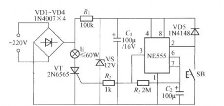
The figure is as shown, it is a delay light circuit with time base circuit, the delay time is decided by the charging time parameters of R3、C2, the data is about 4min. (View)
View full Circuit Diagram | Comments | Reading(543)
Delay light circuit with time base circuit(3)
Published:2011/4/20 23:51:00 Author:Nicole | Keyword: Delay light, time base
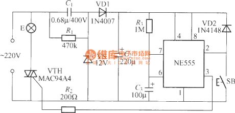
The figure is as shown, the delay time is decided by the values of R3、C3, the data is as shown, the lighting time is about 150s. (View)
View full Circuit Diagram | Comments | Reading(723)
Clock singal circuit composed of TTL circuit
Published:2011/4/20 22:48:00 Author:Nicole | Keyword: Clock singal, TTL
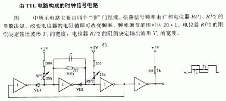
The circuit is as shown, it is composed of four negation gates. The oscillation singal frequency is decided by the parameters of C, potentiometer RP1, RP2. To change the resistance of potentiometer can change the frequency. The adjustable frequency range can reach 20:1. The width of output waves T1 depends on the resistance of potentiometer RP2, and it is the same to output waves T2. (View)
View full Circuit Diagram | Comments | Reading(521)
Timing trigger SCP circuit composed of SGZ35 time control integrated circuit
Published:2011/4/19 4:42:00 Author:Nicole | Keyword: Timing trigger, SCP, time control
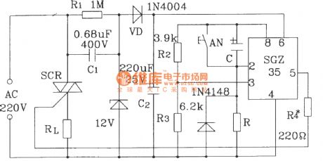
In figure, there are two kinds of timing, delay control circiuts. Setting the value of R, C to make the timing or delay time change between few microseconds and few hours. (View)
View full Circuit Diagram | Comments | Reading(726)
SR63 multi-function festival color lamp with firecrackers sound contorl circuit
Published:2011/4/18 10:07:00 Author:Nicole | Keyword: festival color lamp, firecrackers sound
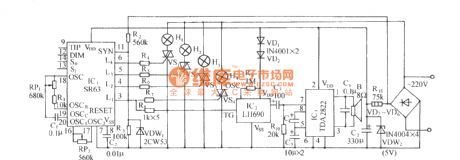
SR63 is a large scale CMOS festival color lamp control special integrated circuit, it has four ways output drive singal, it has eight kinds light changing modes, three of them are chase modes, three of them are dimming modes, one is automatic mixed mode and the other is function lock mode. The color lamp control circuit with the core of SR63 device is as shown. The circuit consists of SR63 color lamp drive circuit, firecrackers sound contorl, audio frequency power amplifier circuit and AC depressurization rectifier circuit. (View)
View full Circuit Diagram | Comments | Reading(525)
M668 touch stepping dimming light circuit
Published:2011/4/19 6:54:00 Author:Nicole | Keyword: stepping dimming light
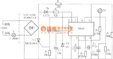
The figure is as shown, it is a touch stepping dimming light with M668 IC, the feature of it is its dimmer uses two-wire system connection, there are only two outgoing lines outward, so it canreplace the ordinary light switch, changing the ordinary light into touch four grades dimming light. (View)
View full Circuit Diagram | Comments | Reading(1042)
Delay light circuit with power switch integrated circuit
Published:2011/4/18 10:09:00 Author:Nicole | Keyword: Delay light, power switch
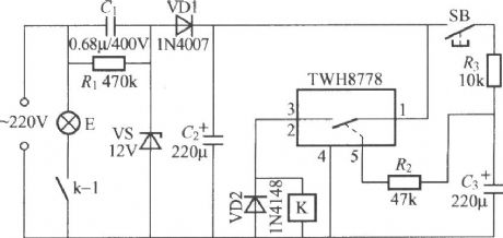
The circuit delay time is decided by the discharge time constant of R2, C3. Increasing or decreasing the capacity of C3 can adjust the delay time. When adopting the polt data, press SB once, the light E will lighting about 15s. (View)
View full Circuit Diagram | Comments | Reading(735)
| Pages:2040/2234 At 2020212022202320242025202620272028202920302031203220332034203520362037203820392040Under 20 |
Circuit Categories
power supply circuit
Amplifier Circuit
Basic Circuit
LED and Light Circuit
Sensor Circuit
Signal Processing
Electrical Equipment Circuit
Control Circuit
Remote Control Circuit
A/D-D/A Converter Circuit
Audio Circuit
Measuring and Test Circuit
Communication Circuit
Computer-Related Circuit
555 Circuit
Automotive Circuit
Repairing Circuit