
Circuit Diagram
Index 2039
Three level circuit topology
Published:2011/4/21 2:16:00 Author:Nicole | Keyword: topology, three level
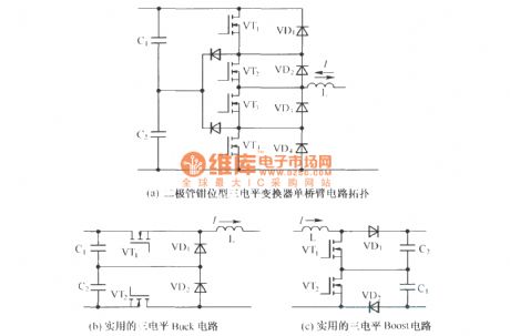
Traditional two level inverting bridge can be divided into Buck and Boost circuit easily, adopting a similar way, we can divede the diode-clamped three-level inverter as shown in figure (a) into three level Buck and Boost circuit with valuable, after necessary improvement. They are as shown in figure (b) and figure (c).
(View)
View full Circuit Diagram | Comments | Reading(756)
IF amplifier circuit diagram
Published:2011/3/30 22:11:00 Author:Ecco | Keyword: IF anplifier

IF amplifier circuit diagram of FM made by TA7302 is as below: (View)
View full Circuit Diagram | Comments | Reading(1746)
SCM controlling fryer circuit diagram
Published:2011/3/30 22:09:00 Author:Ecco | Keyword: SCM controlling fryer
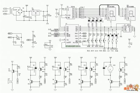
Second order resonance circuit diagram is as below:
(View)
View full Circuit Diagram | Comments | Reading(1197)
Nissan T30 air conditioning system circuit diagram--diesel engine circuit diagram
Published:2011/3/30 22:05:00 Author:Ecco | Keyword: air conditioning system , diesel engine

Nissan T30 air conditioning system circuit diagram--diesel engine circuit diagram is as below:
(View)
View full Circuit Diagram | Comments | Reading(1545)
The configuration and pin circuit diagram of LM378
Published:2011/3/30 21:59:00 Author:Ecco | Keyword: configuration circuit, pin circuit
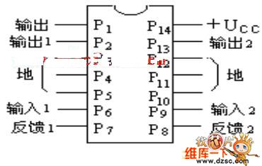
The configuration and pin circuit diagram of LM378 is as 7.46 shown. The main characteriatics: the supply is 10~35V, the output power is 4w, the input resistanceis 3kΩ, the gaining of voltage is 34dB, the bandwidth is 50KHz.
(View)
View full Circuit Diagram | Comments | Reading(647)
Dongfeng EQ1092F truck electronic control harness and principle circuit diagram
Published:2011/3/30 23:08:00 Author:Ecco | Keyword: truck, electronic control harness, principle
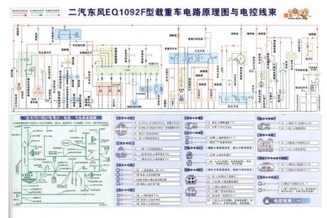
Dongfeng EQ1092F truck electronic control harness and principle circuit diagram is as below:
(View)
View full Circuit Diagram | Comments | Reading(1192)
Negative capacity multiplier circuit diagram
Published:2011/3/30 23:07:00 Author:Ecco | Keyword: Negative capacity, multiplier
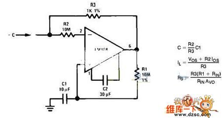
Negative capacity multiplier circuit diagram is as below:
(View)
View full Circuit Diagram | Comments | Reading(1140)
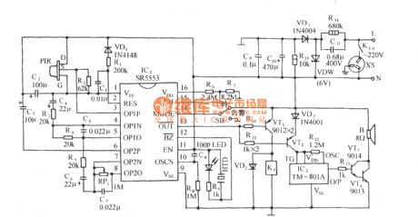
Infrared sensor music socket circuit diagram with SR5553
Published:2011/4/2 2:51:00 Author:Ecco | Keyword: Infrared sensor, music socket
View full Circuit Diagram | Comments | Reading(758)
TOSHIBA AG series rear-projection TV supply circuit diagram
Published:2011/3/30 23:22:00 Author:Ecco | Keyword: rear-projection TV
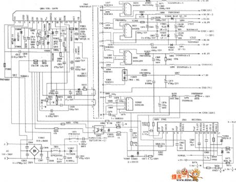
TOSHIBA AG series rear-projection TV supply circuit diagram is as below:
(View)
View full Circuit Diagram | Comments | Reading(3939)
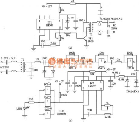
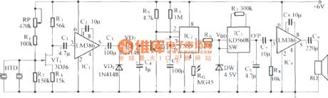
Schematic of The Infrared Rays Wireless Headphone
Published:2011/4/20 4:06:00 Author:TaoXi | Keyword: Infrared Rays, Wireless Headphone
Because of the transmitter circuit of the inductive headphone must installed on the room wall or on the ceiling, so the inductive headphone can not be used outdoor, this is the main weak point of the inductive headphone. But the infrared rays wireless headphone is not in this case, for the flexible infrared rays transmitter circuit, it can be used in electronic teaching, home television and stereo equipment, audio wireless receiver, portable tape recorder, CD, VCD and MP3, makes the dream of wireless Walkman comes ture.
Figure (a) shows the transmitter circuit of the infrared rays wireless headphones. To use it, you need to put the plug XP into TV's or tape recorders's headphones socket. The audio signal coupled by the capacitive Cl, enlarged by the transistor VTl, and transmited the audio wave infrared rays by the infrared emitting diodes VDl and VD2. After installation, you need to adjust the bias resistor R2 to make the quiescent current is l0mA.
Figure (b) shows the receive circuit of the infrared rays wireless headphones. Infrared receiver VD3 ~ VD5 receive the infrared rays signal, converted it into audio signal, and enlarged by the transistor VT2 to bring in the integrated operational amplifier as power amplifier ICl, finally, the output signal exported by the headphone BE. To be able to receive signals all-round, there are three infrared rays receivers in the circuit. When testing, touch the positive electrode of the infrared rays receiver first, then adjust the resistor R4, R5 to make the Hum exported by the BE output largest, and then connect the transmitter circuit, adjusting the volume level of TV or radio cassette player, until the headset's outgoing volume become loud and clear.
(View)
View full Circuit Diagram | Comments | Reading(2948)
The circuit diagram of key to Cadillac car
Published:2011/3/30 23:21:00 Author:Ecco | Keyword: key to Cadillac car
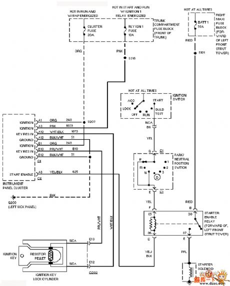
The circuit diagram of key to Cadillac car is as below:
(View)
View full Circuit Diagram | Comments | Reading(557)
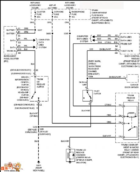
The trunk opening circuit diagram of Cadillac
Published:2011/3/30 23:25:00 Author:Ecco | Keyword: trunk opening
View full Circuit Diagram | Comments | Reading(608)
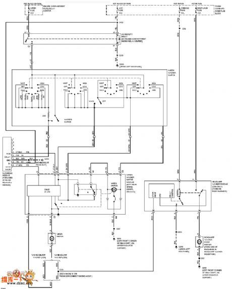
Cadillac wiper washer circuit diagram with rain sense function
Published:2011/3/30 23:24:00 Author:Ecco | Keyword: wiper washer, rain sense function
View full Circuit Diagram | Comments | Reading(569)
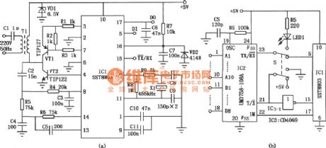
Power Line Communication Transceiver Circuit
Published:2011/4/20 6:25:00 Author:TaoXi | Keyword: Power Line Communication, Transceiver Circuit, LM567
This electric circuit is the single-line power communication transceiver application circuit. It sends the analog and digital signals by 220V or 380V low-voltage power lines to complete wired communications. Figure (a) is the single-line power carrier transmission circuit, the core component IC1 is the audio PLL IC (LM567); Figure (b) is the single-line power carrier receiver circuit. (View)
View full Circuit Diagram | Comments | Reading(12086)
Schematic Of AN7105 Single Cassette Stereo Player
Published:2011/4/20 8:09:00 Author:TaoXi | Keyword: Single Cassette, Stereo Player, AN7105
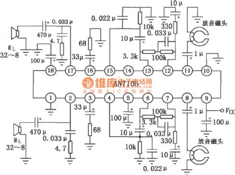
The schematic of AN7105 Single Cassette Stereo Player is shown in the figure. (View)
View full Circuit Diagram | Comments | Reading(2184)
Circuit Of SN75064~SN75067 Semi-finals Current Darlington Switches
Published:2011/4/20 9:08:00 Author:TaoXi | Keyword: Semi-finals, Current Darlington Switches
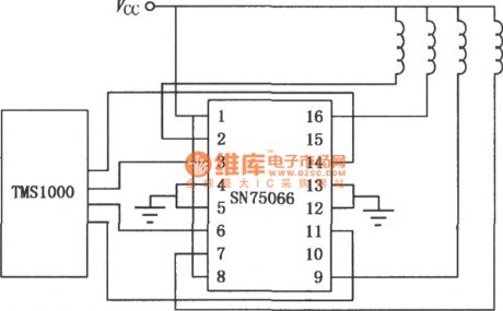
Circuit Of SN75064~SN75067 Semi-finals Current Darlington Switches
(View)
View full Circuit Diagram | Comments | Reading(635)
Circuit Of Intercom Speaker
Published:2011/4/20 21:54:00 Author:TaoXi | Keyword: Intercom Speaker
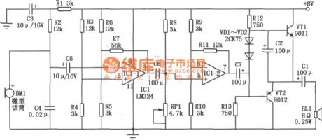
The circuit of intercom speaker in one direction is as shown (the other direction circuit is the same). The core component of the intercom speaker is the LM324 (ICl quad op amp integrated circuit), each amplifier in both directions uses two of four operational amplifiers. The microphone BM1 is one kind of high sensitivity miniature electret speaker devices, the model is 84G9, you should notice the polarity when welding. Two-stage op-amp ICl-1, ICl-2 and the external components make up the negative-feedback amplifier. R7, R11 are the negative-feedback resistor which is used to improve the stability of the circuit. Potentiometer RPl is used to fine-tuning the operating point, make the waveform symmetry, also reduce the non-linear distortion. Resistor Rl, capacitor C3 form the decoupling filter circuit to reduce the power supply hum. (View)
View full Circuit Diagram | Comments | Reading(2250)
Electronic dog triggered by footstep
Published:2011/4/1 1:45:00 Author:Ecco | Keyword: Electronic dog
View full Circuit Diagram | Comments | Reading(555)
Circuit Of BA1404/1404F FM Stereo Transmitter
Published:2011/4/20 22:05:00 Author:TaoXi | Keyword: FM Stereo, FM Stereo Transmitter
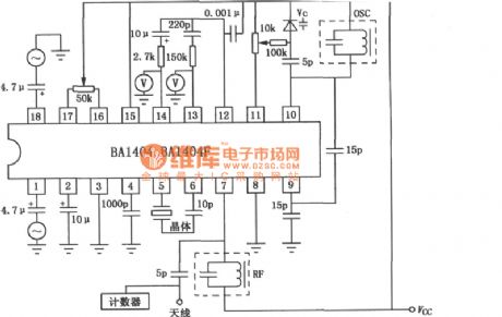
The Circuit Of BA1404/1404F FM Stereo Transmitter is as shown. (View)
View full Circuit Diagram | Comments | Reading(2213)
Coded transmitting circuit diagram composed of TC9148
Published:2011/4/1 4:04:00 Author:Ecco | Keyword: Coded transmitting

Coded transmitting circuit diagram composed of TC9148 is as below:
TC91 series infrared remote controlling coded integrated circuit is a massive integrated circuit which adopts CMOS technology. And TC9148 is a coded transmitting circuit. TC9149 and TC9150 are topical empty receiving circuits. > (View)
View full Circuit Diagram | Comments | Reading(2140)
| Pages:2039/2234 At 2020212022202320242025202620272028202920302031203220332034203520362037203820392040Under 20 |
Circuit Categories
power supply circuit
Amplifier Circuit
Basic Circuit
LED and Light Circuit
Sensor Circuit
Signal Processing
Electrical Equipment Circuit
Control Circuit
Remote Control Circuit
A/D-D/A Converter Circuit
Audio Circuit
Measuring and Test Circuit
Communication Circuit
Computer-Related Circuit
555 Circuit
Automotive Circuit
Repairing Circuit