
Circuit Diagram
Index 2036
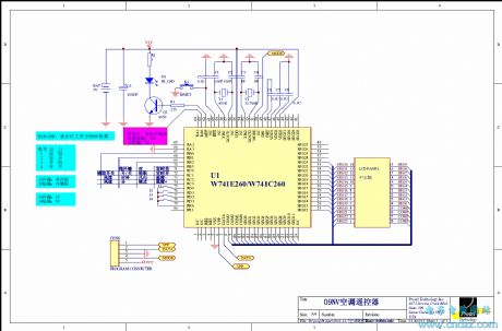
TCL Air conditioning remote control circuit
Published:2011/4/20 3:47:00 Author:Rebekka | Keyword: Air conditioning , remote control circuit
View full Circuit Diagram | Comments | Reading(2627)
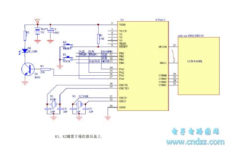
100 in 1 Multi-function air-conditioning remote control circuit
Published:2011/4/20 5:01:00 Author:Rebekka | Keyword: Multi-function remote control , air-conditioning
View full Circuit Diagram | Comments | Reading(873)
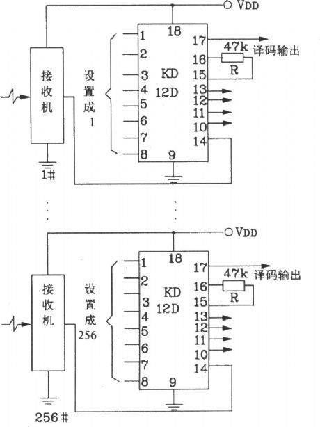
Composed of KD-12F 256 road-type function remote control receiver and the receiver application circuit
Published:2011/4/20 4:35:00 Author:Rebekka | Keyword: remote control receiver , receiver application circuit
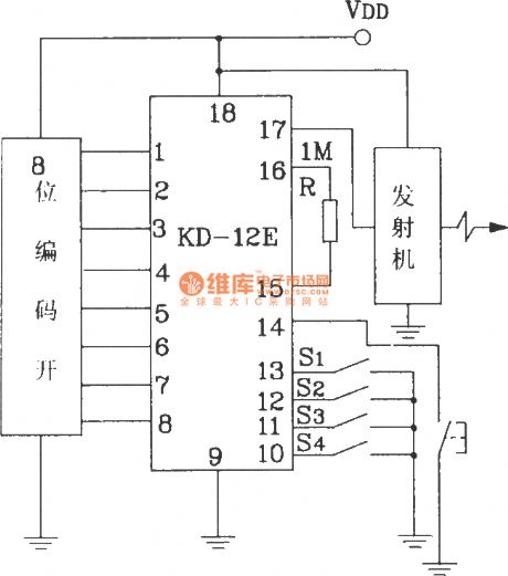
Composed of KD-12E 256 multi-function remote control transmitter application circuit.
Composed of KD-12E 256 multi-function remote control receiver application circuit.
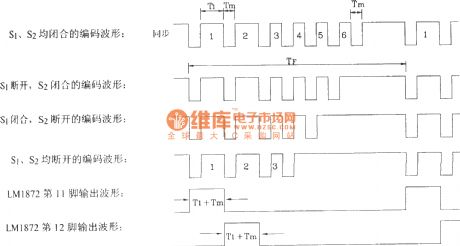
Each way of 256 multi-function remote control transmitter / receiver circuit can achieve 16 different control functions by setting S1 ~ S4 encoded switches.
(View)
View full Circuit Diagram | Comments | Reading(646)
Composed of FDD400/JDD400 multiple alarm system circuit diagram
Published:2011/4/21 2:11:00 Author:Rebekka | Keyword: multiple alarm system

The multiple wireless alarm system is composed of FDD400/JDD400 and integrated digital decoding circuit VD5026/VD5027 (View)
View full Circuit Diagram | Comments | Reading(1070)
Composed of LM1871 and 1872 typical remote control transmitter and receiver circuit diagram
Published:2011/4/21 2:00:00 Author:Rebekka | Keyword: remote control , transmitter and receiver

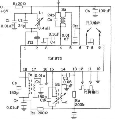
LM1871/1872 a large-scale electric guitar without remote control transmitter / receiver ASIC.
LM1871/1872 shape pin function diagram.
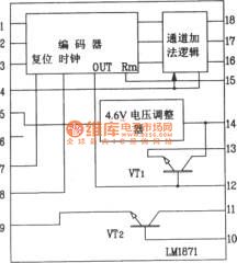
LM1871 internal schematic.
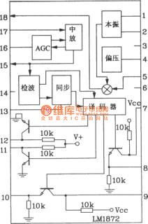
LM1872 internal block diagram.
LMl871/1872 radio-controlled special chip operating voltage range is 3 ~ 9V; Transmitter chip LMl871 frequency up to 80MHz, frequencies up to 80MHz. It is optional; It contains the oscillator, the transmitter and encoder; Channels are programmable, and the RF output power is adjustable. General remote control distance up to tens of meters. If increase the supply voltage appropriately, and add one or two high-amp circuit, the remote control distance can be increased to l~2km.
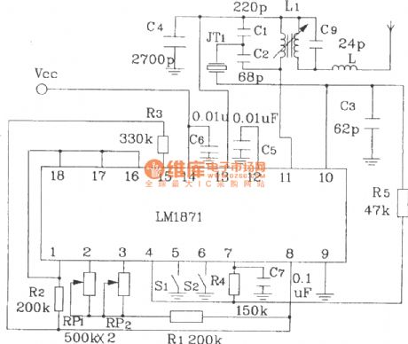
Here is a typical remote control transmitter / receiver circuit composed of LM1871/1872:
(View)
View full Circuit Diagram | Comments | Reading(2973)
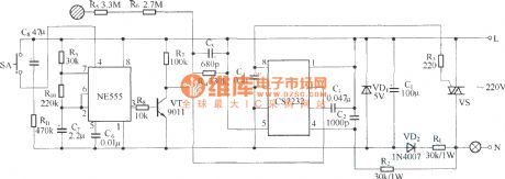
Composed of CS7237 self-extinguishing touch dimmer circuit circuit diagram
Published:2011/4/21 2:02:00 Author:Rebekka | Keyword: touch dimmer self-extinguishing
View full Circuit Diagram | Comments | Reading(898)
Composed of TX-2 and RX-2 four-channel wireless remote control toy car circuit diagram
Published:2011/4/21 3:46:00 Author:Rebekka | Keyword: four-channel , wireless remote control, toy car
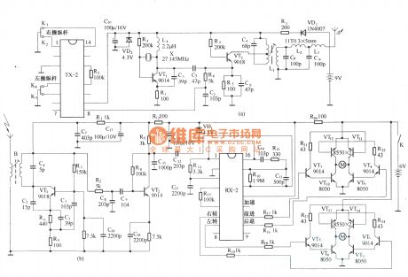
HS101/HS201 are a pair of tiny radio transceiver components. The working frequency is 280MHz. It is suitable for digital signal transmission. The control distance is 30 ~ 100m. All the components including the antenna are packaged in one. It is easy to use. The four-channel remote control switch circuit composed of HS101/HS201 is shown as below. (View)
View full Circuit Diagram | Comments | Reading(3976)
Composed of TM701 and TM702 RF remote control transmitter and receiver circuit diagram
Published:2011/4/21 4:14:00 Author:Rebekka | Keyword: RF remote control, transmitter and receiver

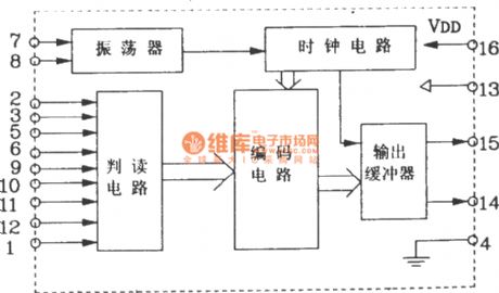
TM701/702 dedicated remote control transmitter / receiver integrated circuits and TM703/702 infrared remote control transmitter / receiver integrated circuits are dedicated remote control devices of the same class.
TM701 shape pin map.
TM701 internal block diagram.
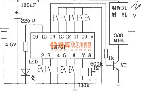
RF remote control transmitter circuit composed of TM701.
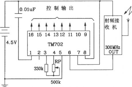
Radio remote control receiver circuit composed of TM702.
(View)
View full Circuit Diagram | Comments | Reading(3634)
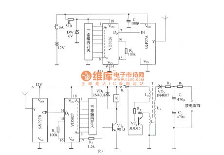
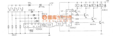
Composed of S&P27A/S&P278 long-distance remote control switch circuit diagram
Published:2011/4/21 1:11:00 Author:Rebekka | Keyword: remote control switch
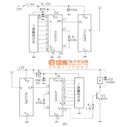
(a) shows the remote control transmitter circuit. The circuit uses the digital coding circuit VD5026 as address encoder. It uses encoding a three-state. It can be composed of multiple extensions (based on the need to launch an extension or as a receiver as the extension). (b) shows the receiver circuit, which consists of components and decoding circuit to receive and relay K VD5027 composition.
(View)
View full Circuit Diagram | Comments | Reading(2756)
Composed of S&P27A/S&P27B radio-controlled explosive device circuit diagram
Published:2011/4/21 1:06:00 Author:Rebekka | Keyword: Radio-controlled explosive device
In the exploitation of mines and blasting of rock material. It is more flexible to use radio remote control detonation than wire control. And it is more reliable and economy. The figure shows the radio remote control of components of S & P27 radio-controlled detonator to detonate detonation device.
(A) is a radio remote control transmitter circuit; (b) is a radio receiver and demodulation circuit. (View)
View full Circuit Diagram | Comments | Reading(2135)
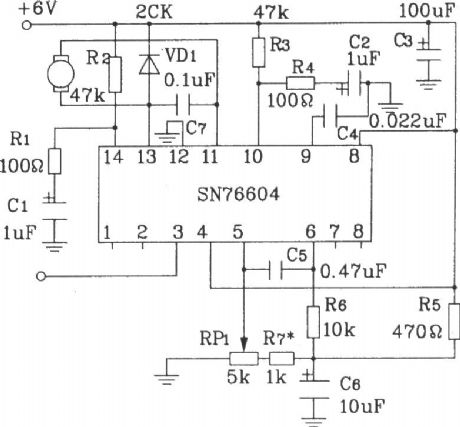
Composed of MC3372 and MC341196D 45MHz band radio receiver circuit diagram
Published:2011/4/21 4:20:00 Author:Rebekka | Keyword: band radio receiver

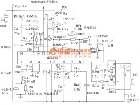
MC3373-specific integrated circuit radio receiver is low-power narrowband FM receiving device of Motorola. It operates up to 100MHz.
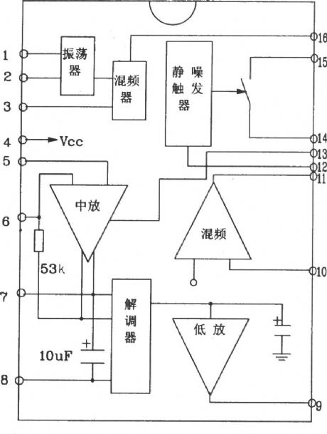
MC3372 pin function diagram form.
MC3372 internal block diagram.
45MHz band radio receiver circuit composed of MC3372 and MC341196D.
(View)
View full Circuit Diagram | Comments | Reading(3039)
Composed of T630 and T631 wireless mini remote control circuit diagram
Published:2011/4/21 1:24:00 Author:Rebekka | Keyword: wireless mini remote control
View full Circuit Diagram | Comments | Reading(1363)
Composed of T630/T631 long-wave wireless remote control circuit diagram
Published:2011/4/21 1:22:00 Author:Rebekka | Keyword: long-wave wireless remote control
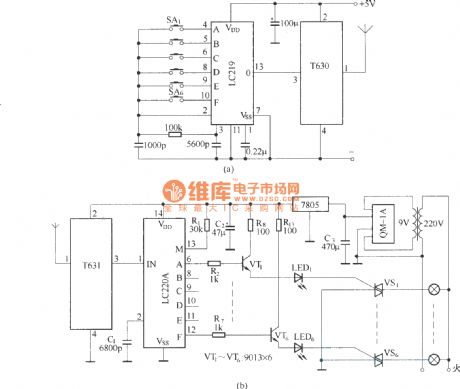
The circuit uses the long-wave wireless transceiver T630/T631, controlled 6-channel load. The features are low-power, high anti-interference ability and simple structure etc. (View)
View full Circuit Diagram | Comments | Reading(2345)
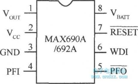
Microcomputer system power supply monitoring integrated chip MAX690A/692A
Published:2011/4/21 4:34:00 Author:Nicole | Keyword: Microcomputer system, integrated chip, power supply monitoring
View full Circuit Diagram | Comments | Reading(804)
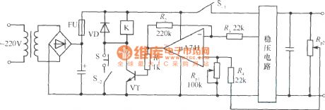
Circuit example of regulated power supply adding overvoltage protection
Published:2011/4/21 4:04:00 Author:Nicole | Keyword: regulated power supply, overvoltage protection
View full Circuit Diagram | Comments | Reading(570)
Regulated power supply circuit without transformer
Published:2011/4/21 4:27:00 Author:Nicole | Keyword: regulated power supply, transformer
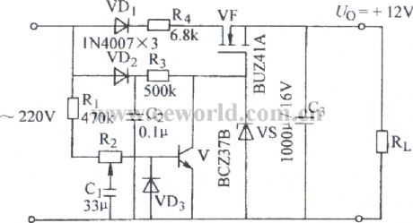
View full Circuit Diagram | Comments | Reading(2301)
Walkman external power circuit without AC noise
Published:2011/4/21 4:28:00 Author:Nicole | Keyword: Walkman, external power, AC noise
View full Circuit Diagram | Comments | Reading(600)
Pocket switch power supply charger circuit
Published:2011/4/21 3:56:00 Author:Nicole | Keyword: switch power supply, charger
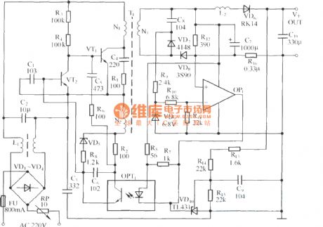
View full Circuit Diagram | Comments | Reading(708)
Voltage type drive circuit
Published:2011/4/21 3:51:00 Author:Nicole | Keyword: Voltage type drive

The drive circuit is as shown in figure (a), it is suitable for low frequency and low power drive, when the control singal Ui is high level, VT1 turns on, the switch tube(IGBT) controlled by output voltage Uo turns on too; when the control singal Ui is low level, VT2 turns on, the switch tube(IGBT) controlled by output voltage Uo turns off. The drive circuit is as shown in figure (b), it adopts push pull circuit composed of FET, the working principle is the same as figure (a). The high frequency peak value drive current of this circuit can reach more than 10A, it is suitable for high power IGBT devices. (View)
View full Circuit Diagram | Comments | Reading(506)
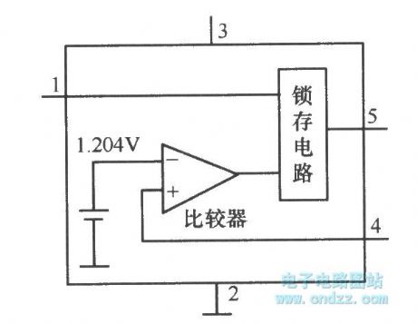
Micro-power voltage detection integrated chip MAX834/835 with latched output
Published:2011/4/21 4:31:00 Author:Nicole | Keyword: voltage detection, integrated chip, latched output
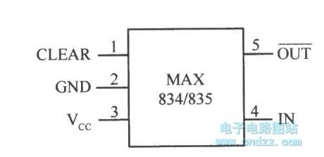
View full Circuit Diagram | Comments | Reading(670)
| Pages:2036/2234 At 2020212022202320242025202620272028202920302031203220332034203520362037203820392040Under 20 |
Circuit Categories
power supply circuit
Amplifier Circuit
Basic Circuit
LED and Light Circuit
Sensor Circuit
Signal Processing
Electrical Equipment Circuit
Control Circuit
Remote Control Circuit
A/D-D/A Converter Circuit
Audio Circuit
Measuring and Test Circuit
Communication Circuit
Computer-Related Circuit
555 Circuit
Automotive Circuit
Repairing Circuit