
Circuit Diagram
Index 2011
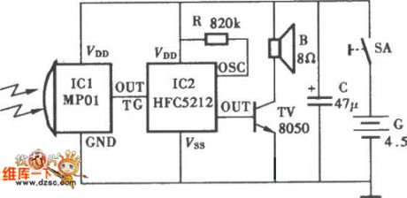
Remote Control Electric Equipment Circuit
Published:2011/4/22 4:22:00 Author:Christina | Keyword: Remote Control, Electric Equipment

The Remote Control Electric Equipment Circuit is as shown:
(View)
View full Circuit Diagram | Comments | Reading(1162)
Infrared Ray Probe Alarm Circuit
Published:2011/4/22 3:22:00 Author:Christina | Keyword: Infrared Ray, Probe, Alarm
The Infrared Ray Probe Alarm Circuit is as shown:
(View)
View full Circuit Diagram | Comments | Reading(578)
Remote Control Helicopter Transmission Circuit
Published:2011/4/24 21:11:00 Author:Christina | Keyword: Remote Control Helicopter, Transmission
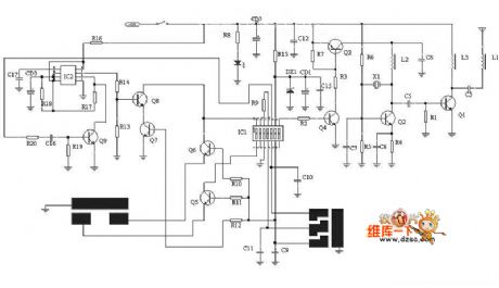
The Remote Control Helicopter Transmission Circuit is as shown:
(View)
View full Circuit Diagram | Comments | Reading(6584)
Infrared mouse circuit diagram
Published:2011/4/24 8:13:00 Author:Rebekka | Keyword: Infrared mouse
View full Circuit Diagram | Comments | Reading(3303)
Small Irradiation Measure Circuit
Published:2011/4/24 9:08:00 Author:Christina
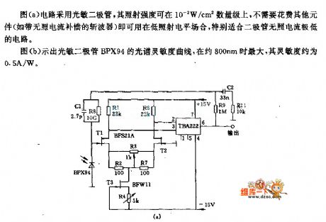
The circuit of figure (a) uses the photodiode, the irradiation intensity is about 0.01W/c㎡, there is no need to use the other devices such as the chopper without current compensation, so this circuit can be used in the low-level radiation conditions, particularly suitable for the low-level radiation diode circuit.
Figure (b) is the spectral sensitivity curve of photodiode BPX94, when the wavelength is about 800nm, the maximum sensitivity is about 0.5A/W.
(View)
View full Circuit Diagram | Comments | Reading(641)
Composed of KD704 and KD705 RF remote control transmitter and receiver circuit diagram
Published:2011/4/21 3:54:00 Author:Rebekka | Keyword: remote control , transmitter and receiver
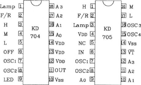
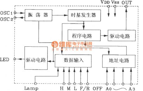
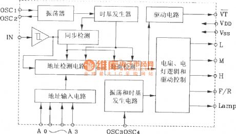
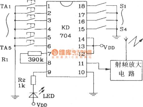
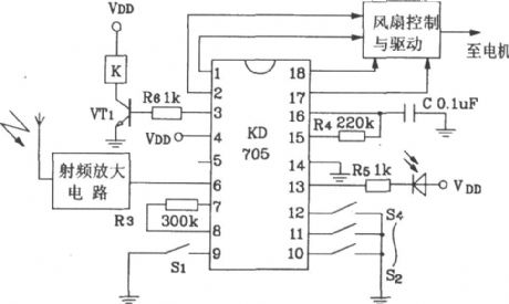
KD704/KD705 is a pair of RF remote control transmitter / receiver CMOS LSI specifically designed for electric fans and lights.
KD704/705 shape pin map.
KD704 internal block diagram.
KD705 internal block diagram.
RF remote control receiver circuit composed of KD705.
(View)
View full Circuit Diagram | Comments | Reading(2985)
Composed of HS101/HS201 4 channels remote control switch circuit diagram
Published:2011/4/21 3:47:00 Author:Rebekka | Keyword: 4 channels remote control switch
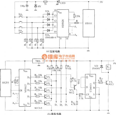
(a) is transmission circuit;(b) is receiving circuit.
HS101/HS201 are a pair of tiny radio transceiver components. The working frequency is 280MHz. It is suitable for digital signal transmission. The control distance is 30 ~ 100m. All the components including the antenna are packaged in one. It is easy to use. The four-channel remote control switch circuit composed of HS101/HS201 is shown as above. (View)
View full Circuit Diagram | Comments | Reading(4029)
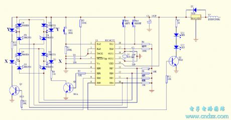
Remote Control Helicopter Receiver Circuit
Published:2011/4/24 9:41:00 Author:Christina | Keyword: Remote Control, Helicopter, Receiver
The Remote Control Helicopter Receiver Circuit is as shown:
(View)
View full Circuit Diagram | Comments | Reading(9642)
Light intensity control switch circuit
Published:2011/4/24 10:06:00 Author:Christina | Keyword: Light intensity, control switch
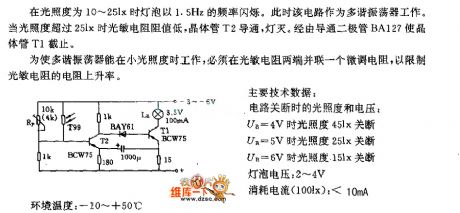
When the light intensity is 10-25lx, The bulb's frequency of flashing is 1.5Hz. At this point this circuit works as the multivibrator. When the light intensity is over 25lx, resistance of the photosensitive resistor become lower, transistor T2 turns on, the light turns off. The circuit close the transistor T1 by diode BA127.
To let the multivibrator work under small illumination, we must parallel a fine-tuning resistance at both ends of the photoresistor to limit the resistance increase rate.
Main technical data:
The light intensity and voltage when the circuit shut down:
when UB=4V, light intensity is 45lx
when UB=5V, light intensity is 25lx
when UB=6V, light intensity is 15lx
Lamp voltage: 2V to 4V
Current consumption (100lx): <10mA
(View)
View full Circuit Diagram | Comments | Reading(810)
Composed of TDC1808/TDC1809 digital coding control circuit diagram
Published:2011/4/20 22:51:00 Author:Rebekka | Keyword: digital coding control
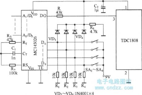
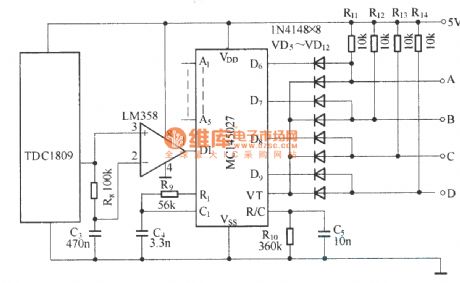
TDC1808/TDC1809 is a pair of wireless remote control transmitter and receiver component. They use an internal antenna, transmitting digital signals or analog signals. It is suitable for a variety of wireless remote control device. The features are small volume, long remote distance, high anti-interference ability etc. Digital coding control circuit is composed by TDC1808/TDC1809. The circuit is shown as above.
(View)
View full Circuit Diagram | Comments | Reading(2412)
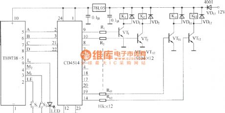
12 way wireless remote control circuit diagram(TH9738)
Published:2011/4/20 22:52:00 Author:Rebekka | Keyword: remote control circuit
View full Circuit Diagram | Comments | Reading(1812)
Photoresistor Light Control Switch Circuit
Published:2011/4/24 19:23:00 Author:Christina | Keyword: Photoresistor, Light Control Switch
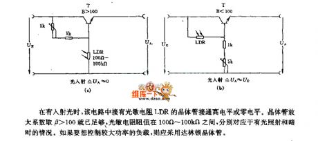
When there is incident light,the transistor of LDR photoresistor connected to the high or zero level. Amplification factor of transistor is β>100, resistance of the photoresistor is between 100 ohms to 100 kilohms, correspond to the bright light and dark conditions. If you want to control the high power load, the darlington transistor should be used. (View)
View full Circuit Diagram | Comments | Reading(2783)
Composed of BIC1222 DC converter circuit diagram
Published:2011/4/25 5:01:00 Author:Rebekka | Keyword: DC converter
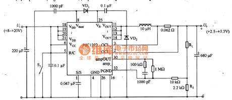
Figure 22 is a DC converter circuit constituted by the BIC1222. BIC1222 has two synchronous rectifier power MOSFET, the control circuit, over-current protection circuit and thermal protection circuit module. It has on and off function. The circuit's input voltage is +8 ~ +20 V, output voltage is + 2.5 ~ +5.3 V, output current is 5A. The output voltage is setted by external resistors R1 and R2 in the range of +2.5 ~ +12 V. Output voltage U. = [2.45V (R1 +2 R)] / R2. In the circuit, R2 = 2.2KΩ, U. = 2.5V, R1 = 47Ω; U. 3.3V, R1 = 770Ω; U. 5.0V, R1 = 2.3KΩ. (View)
View full Circuit Diagram | Comments | Reading(856)
Flashing circuit with astable trigger
Published:2011/4/25 0:43:00 Author:Nicole | Keyword: flashing, astable trigger
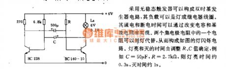
Double time base generator circuit can be composed of astable trigger, the load can be light or relay coil. The on/off time depend on the capacitance and base resistance. One of two collector resistances can be replaced by light, then to form the light flashing circuit. The time of light on/ off is decided by R, C, such as C=50μF, R=2.7KΩ, then the light time is about 0.3s, the off time is about 1s. (View)
View full Circuit Diagram | Comments | Reading(594)
Touch Delay Switch Circuit Composed of NAND Gate
Published:2011/4/25 2:43:00 Author:TaoXi | Keyword: NAND Gate, Touch Delay Switch
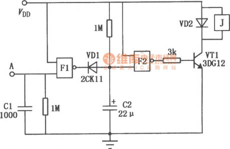
The Touch Delay Switch Circuit Composed of NAND Gate is as shown:
(View)
View full Circuit Diagram | Comments | Reading(723)
Light Delay Switch Circuit Composed Of Inverter
Published:2011/4/25 2:45:00 Author:TaoXi | Keyword: Inverter, Light Delay Switch
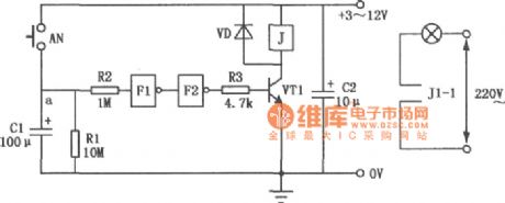
The Light Delay Switch Circuit Composed Of Inverter is as shown:
(View)
View full Circuit Diagram | Comments | Reading(557)
Circuit of Electronic Selector Switch Composed of CD4017 and CD4066
Published:2011/4/25 2:46:00 Author:TaoXi | Keyword: Electronic, Selector Switch
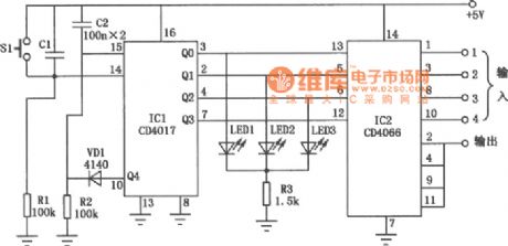
The Circuit of Electronic Selector Switch Composed of CD4017 and CD4066 is as shown:
(View)
View full Circuit Diagram | Comments | Reading(7017)
The Battery Charging Application Circuit composed of Wll7/W217/W317
Published:2011/4/22 1:51:00 Author:Crystal Liu | Keyword: battery application, circuit
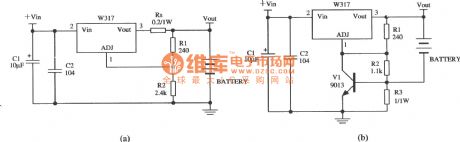
Thefigure shows a battery application circuit consists of three terminal control integrated circuit.Figure (a) shows a circuit of charger with constant pressure and Current limiting,among them the Rs is used to limit current,Lower initial charge rate;Figure(b) shows a charger circuit of limiting current,among them ,the resistance R3 and thetransistorare used to limit maximum charge current.
(View)
View full Circuit Diagram | Comments | Reading(1833)
TC9465F Karaoke Single-chip LSI Circuit
Published:2011/4/25 2:49:00 Author:TaoXi | Keyword: Karaoke, Single-chip, LSI
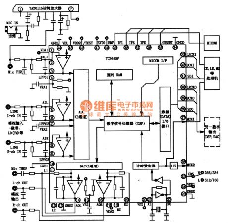
The TC9465F is one kind of Karaoke Single-chip LSIwhich is produced by the Toshiba company, and this device is designed for the LD/CD sing stereo equipment and VTR.
1.TC9465F's block diagram and pin function
The TC9465F Manifold-circuit has three analog channels and a digital stereo input port and two simulation and output ports; the DAC using the Σ-△ modulation and oversampling mode; the built-channel ADC is the pre-filter amplifier with the 64Kbit delay RAM and the digital signal processor (DSP).etc.
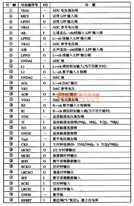
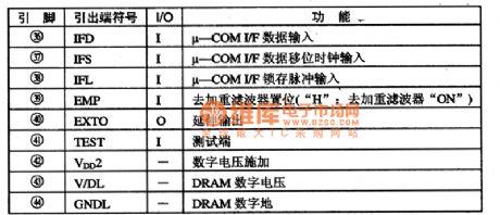
The TC9465F's inside block diagram and typical application circuit is shown as figure 1. This IC is in the 44-pin QFP package, the integrated circuit's pin functions and data are listed in Table 1.
Table 1. The Pin Functions Of The TC9465F IC
Figure 1. The TC9465F's inside block diagram and typical application circuit
2. The main electrical parameters of TC9465F
The TC9465F IC built-in ADC's total harmonic distortion is THD=-65dB, the SNR is S/N = 78dB (typical); the TC9465F's 2-channel digital to analog converter (DAC) has the third analog filter with THD=-85dB, S/N=93dB(typical).
The TC9465FR's input voltage (V(IN)) range is from -0.3V to (V(DD)+0.3) V, and the maximum power (Po) is 5mW. The operating voltage is 5±0.5V, the supply current is 48mA (typical value).
3.TC9465F typical application circuit
The TC9465 manifold's typical application circuit is shown in Figure 1. (View)
View full Circuit Diagram | Comments | Reading(2467)
TCM5089 microcomputer dial integrated circuit
Published:2011/4/24 22:51:00 Author:TaoXi | Keyword: microcomputer, dial integrated
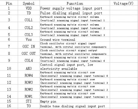
The TCM5089 microcomputer dial integrated circuit can be used in communication equipment as the pulse / tone signal generator.
1.Features
The TCM5089 IC has the pulse / tone dial compatible circuit, key switch signal encode and decode circuit.
2.Pin functions and data
The pin functions and data of the TCM5089 IC is as shown in table 1.
Table 1. The pin functions and data of the TCM5089 IC (View)
View full Circuit Diagram | Comments | Reading(771)
| Pages:2011/2234 At 2020012002200320042005200620072008200920102011201220132014201520162017201820192020Under 20 |
Circuit Categories
power supply circuit
Amplifier Circuit
Basic Circuit
LED and Light Circuit
Sensor Circuit
Signal Processing
Electrical Equipment Circuit
Control Circuit
Remote Control Circuit
A/D-D/A Converter Circuit
Audio Circuit
Measuring and Test Circuit
Communication Circuit
Computer-Related Circuit
555 Circuit
Automotive Circuit
Repairing Circuit