
Circuit Diagram
Index 2009
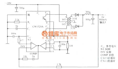
4V DC convertor connected by CWI524A
Published:2011/4/22 6:51:00 Author:May | Keyword: 4V, DC, convertor
View full Circuit Diagram | Comments | Reading(462)
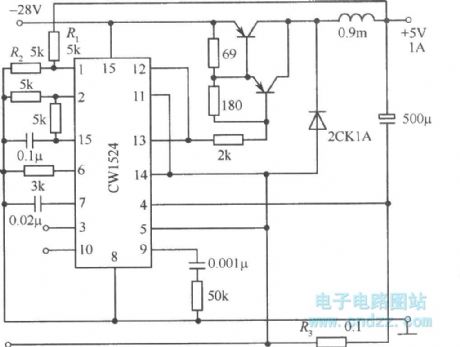
Step-down chopper type switching power supply circuit composed of CWl524A
Published:2011/4/22 4:15:00 Author:May | Keyword: Step-down chopper type, switching power supply
View full Circuit Diagram | Comments | Reading(1568)
Half bridge type switching regulated power supply circuit composed of CWl524
Published:2011/4/22 4:19:00 Author:May | Keyword: Half bridge type, switching regulated power supply

View full Circuit Diagram | Comments | Reading(665)
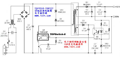
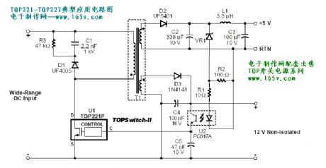
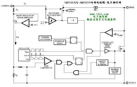
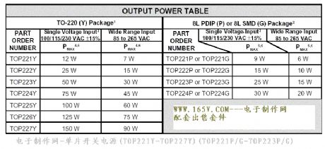
Application circuit of single chip switching power supply TOP221-TOP227
Published:2011/4/21 1:05:00 Author:May | Keyword: single chip, switching power supply
View full Circuit Diagram | Comments | Reading(8365)
Single end fly back type power converter circuit with energy returning winding diode clampling circuit
Published:2011/4/21 1:22:00 Author:May | Keyword: Single end, fly back, power converter, energy returning winding, diode clampling
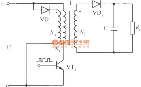
The following diagram is single end fly back type power converter circuit with energy returning winding diode clamping circuit. The turn number of N3 winding is equal to N1's, and the polarity of them is opposite. When VT1 is cutting off and the potential of collector increasing two times of input voltage, diode VD2 is breaking over, VT1's collector potential is clamped, leakage inductance stored energy is retuning to network.
In order to get relatively good effects, N2 and N1 must close coupling, and clamping diode VD2 can break over fast.
(View)
View full Circuit Diagram | Comments | Reading(594)
The inside circuit diagram of TIP131 and TIP132 crystal triode
Published:2011/3/24 3:34:00 Author:Ecco | Keyword: crystal triode
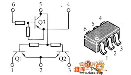
The inside circuit diagram of TIP131 and TIP132 crystal triode is as below:
(View)
View full Circuit Diagram | Comments | Reading(670)
The circuit diagram of frequency modulation receive in 50 KHz
Published:2011/3/24 3:28:00 Author:Ecco | Keyword: frequency modulation receive in 50 KHz
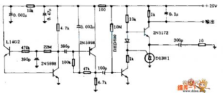
This circuitry is applied in pulse speed control system. In this system, the rate of pulse speed of modulating beam of light in the fiberis changed by the transimitter, and the rate of pulse speed is changed up and down in the center of 50KHZ frequency. The L14 G2 optics transistor changes the modulating light as semaphore of radio frequency for demodulation, and it can restore originally semaphore of radio frequency. (View)
View full Circuit Diagram | Comments | Reading(677)
300kHz Signal generator
Published:2011/4/21 5:32:00 Author:Ecco | Keyword: 300kHz , Signal generator
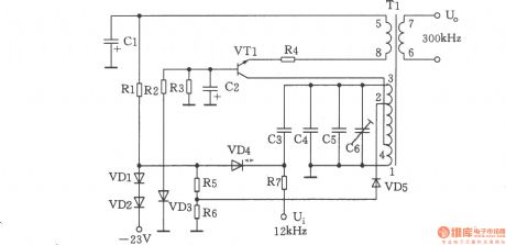
The chart shows the 300kHz signal generator. It is a voltage-controlled oscillator which is composed of VT1, T1, VD4 and related components. VCO use LC tuned collector, VTl is the oscillating tube, the 1 to 3 inductor winding of varactor diode VD4, and the capacitors C3 ~ C6 and transformer T1 form a tuning loop, the back biased work of varactor diode VD4 can control voltage which is applied to the negative side, and it can change its electrical capacity. The oscillating signal is from the output windings 6 to 7 of Tl. And C6 is the frequency tuning capacitor. VD3 stablizes oscillation voltage level, stable voltage is 6.8V ± 0.2V. Selection of components: transistor VT1: 3DG6C, β = 65 ~ 85. Diode VD1, VD2: 2CPl4, VD5: 2CK18. Zener diode VD3: 2CWl4. Varactor diode VD4: 2CC5. Resistor R1: 3.6k, R2: 3.3k, R3: 5.1k, R4: 510Ω, R5: 3.9k, R6: 3k, R7: 100k, the models are RTX-0.125W. Capacitors Cl, C2: 5μF30V, C3: 51pFl00V, C4: 820pFl00V, C5: (matching when measuring), C6: 20pF. Variable device T1: model L22, A = 100. L1-4: Φ0.29mm, around 27 turns, L2-3: Φ0.29mm, turn around l8, L4-2: Φ0.29ram with 9 turns, L5-8: Φ0.29mm with 7 turns, L6- 7: ΦO. 29mm with 6 turns. L1-3 = 292μH, allowable error range: 0 ~ 10μH. (View)
View full Circuit Diagram | Comments | Reading(1100)
70MHz parallel crystal oscillator
Published:2011/4/20 22:47:00 Author:Ecco | Keyword: 70MHz, parallel, crystal oscillator
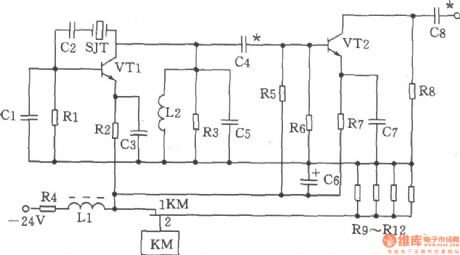
The chart shows 70MHz parallel crystal oscillator circuit. The oscillator is mainlycomposed ofthe transistor VTl, crystal SJT and capacitor Cl, C5 and other components. Selection ofcomponents: capacitors Cl, 20p, C2 to 100p, C3, C7 to 820p, C4 to 56p, C5, C8 to 47p, C6 to 47μF/50V. Inductor Ll is 22μH (color code inductance), L2 is 0.3μH. Resistor Rl is 1.6kΩ, R2 is 1kΩ, R3 is 750Ω, R4 is 180Ω, 1W, R5 is 1.3kΩ, R6 is 3kΩ, R7 is 360Ω, R8 is 470Ω, R9 ~ R12 is 300Ω, 2W. Transistor VTl, VT2choose 3DG828, 65 ≤ β ≤ 115. Crystal SJTchooses JA98-70MHz. Relay KM is JUC-1M.
(View)
View full Circuit Diagram | Comments | Reading(832)
4kHz harmonic generator
Published:2011/4/21 5:06:00 Author:Ecco | Keyword: 4kHz , harmonic , generator
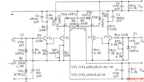
Harmonic generator is the differential type, which consists of a symmetrical differential amplifier circuit to impulse the difference in half-cycle rectangularly, and it is coupled push-pull by output transformer, the harmonic circuit is simple, convenience for measurement, low-cost, and it retains its symmetric pulse characteristics, its performance is similar with magnetic saturation type. The chart shows 4kHz harmonic generator circuit. Its frequency is controlled by the master oscillator, odd and even harmonics can be used as carrier and pilot of presetting, accessing, group roads modulation and demodulation for communication machine.
(View)
View full Circuit Diagram | Comments | Reading(1012)
555 ambulance audio circuit
Published:2011/4/25 1:41:00 Author:May | Keyword: 555, ambulance audio
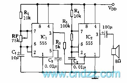
As shown in diagram 21-1, this circuit consists of two ambipolar 555, and it all works at multivbrator state. It is not hard to equate frequency of two oscillators by parameter in the diagram.
f1=1/T=1.44/[(R2+Rp)C1]
When resistance of potentiometer RP changes in the range of 0~75kΩ, corresponding frequency is 14.4Hz~0.9Hz.
f2=1.44/[(R2+2R5)C2]≈700Hz
IC2 is controlled by low frequency square wave of IC1. When output square wave of IC1 is low level, oscillating frequency of IC2 is low; and when output of IC1 is high level, oscillating frequency of IC2 is high ,so the loudspeaker can send out rhythm sound of di-da, di-da . Output sound frequency can change by changing the time constant of R4, R5 and C2. (View)
View full Circuit Diagram | Comments | Reading(1053)
Ultrasonic remote control light switch circuit
Published:2011/4/24 22:21:00 Author:Nicole | Keyword: ultrasonic, remote control light, switch
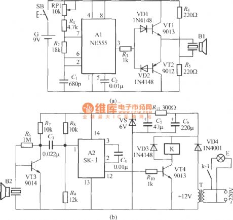
Ultrasonic is invisible, it will not interfere the household appliances, so it is popular among some occasions. The figure is as shown, it is a practical ultrasonic remote control light switch, it consists of ultrasonic remote control transmitter and receiver. The ultrasonic remote control transmitter circuit is shown as figure (a), the 40kHz free running multivibrator is composed of NE555 time base circuit A1, outputed from ③ foot, the electrical signal radiates ultrasound remote control command by VT1, VT2 amplifying and driving ultrasonic transducer B1. RP1 is trimmer resistor, it can adjust oscillation frequency to ensure it work with 40kHz. The ultrasonic remote control receiver circuit is shown as figure (b). It is composed of ultrasonic reception transducer B2, preamplifier VT3, sound control special IC A2, electronic switch and power supply. (View)
View full Circuit Diagram | Comments | Reading(2977)
Pulse amplifier circuit
Published:2011/4/25 20:32:00 Author:Nicole | Keyword: Pulse amplifier
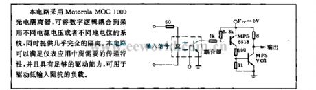
This circuit adopts Motorola MOC1000 photoelectric isolator, it can couple digital logic to the adopted different power supply or level system, they provide almost complete isolation. The circuit can satisfy the need of transfer characteristicin the instrument application, it has enough drive capability, it can be used to drive the low input resistance load. (View)
View full Circuit Diagram | Comments | Reading(969)
Wien Bridge Sine Wave Oscillator Circuit
Published:2011/4/24 20:49:00 Author:Sue | Keyword: Wien Bridge, Sine Wave, Oscillator
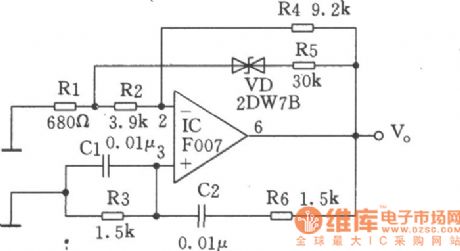
As seen in the figure, the oscillator frequency is around 1kHz, and the circuit uses stabilivolt 2DW78 to stablise the voltage. If we replace the coaxial potentiometer with 1.5kΩ resistance, and connect different resistances with multiband switch,then the output signal frequency can be adjusted continuously. And the maximum oscillator frequncy is decided by frequency characteristics of operational amplifier F007.In low frequency part there should be large resistance and capacitor, but large capacitor can result in unstability or leakage of electricity, so the input impedance of operational amplifier should be as large as possible. (View)
View full Circuit Diagram | Comments | Reading(684)
TC9307AF-008 digital-tuning microprocessor integrated circuit
Published:2011/4/25 20:23:00 Author:TaoXi | Keyword: digital-tuning, microprocessor
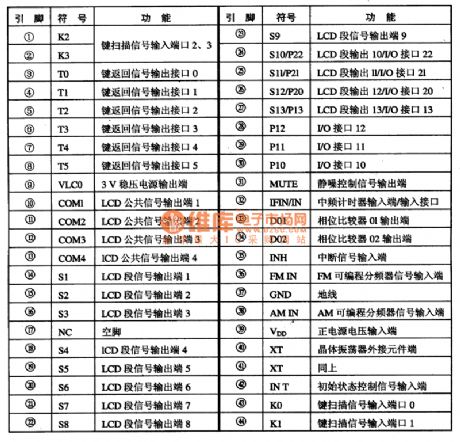
The microprocessor TC9307AF-008 has all functions of the DTS, this means the TC9307AF-008 has the 130MHz prescaler, PLL frequency synthesizer and the LCD driver. If TC9307AF-008 combined with the TD6135AP prescaler, they can receive TV's (VHF, UHF) all channel programs. The digital tuning system which is formed by this IC has the following main functions:
(1)Manual up/down tuning, auto scan tuning, fast tuning and automatic storage tuning.
(2)Can preset 20 radio frequencies and the last radio frequency you have heard.
(3)Clock display with I2h/24h and TIMER function, sleep function.
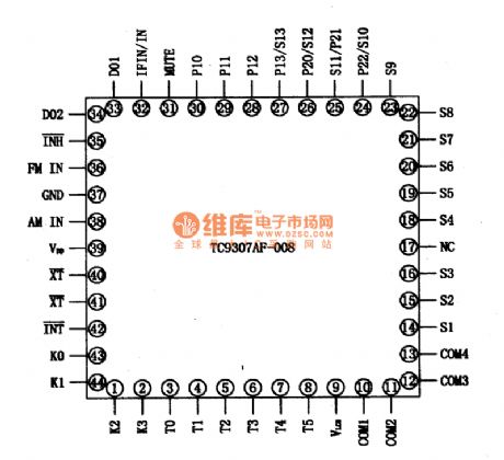
1.Circuit block diagram and pin functions of the TC9307AF-008:
Figure1. Circuit block diagram and pin functions of the TC9307AF-008.
Figure 2. Manifold's pin arrangement of the TC9307AF-008
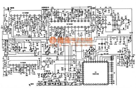
2. Typical application circuit of the TC9307AF-008
Figure 3. Typical application circuit of the TC9307AF-008.
3. Signal process
4. Tips of breakdown (View)
View full Circuit Diagram | Comments | Reading(3054)
BA5104/BA8207K multi-function infrared remote control electric fan with the sound of crickets circuit diagram
Published:2011/4/24 10:26:00 Author:Rebekka | Keyword: electric fans , infrared remote control
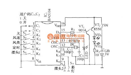
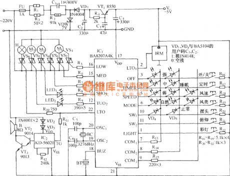
BA5104 coded remote control transmitter circuit:
BA8207K multifunctional infrared remote controlfan with the sound of cricketscircuit:
(View)
View full Circuit Diagram | Comments | Reading(2690)
RF Modulator Circuit Composed of TA7673
Published:2011/4/23 22:46:00 Author:TaoXi | Keyword: RF Modulator
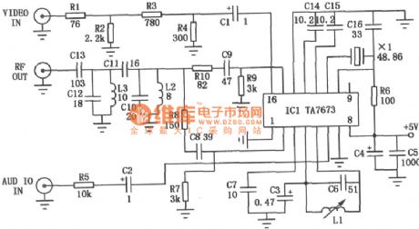
The RF modulator is the very important component in TV, VCR, satellite receiver, format converter, home computer and game machine. This circuit is simple, stable and easy to make, it can be easily connected with a lot kinds of circuit boards. The figure is the circuit of RF modulator, ICl is the modulator ASIC (TA7673), the 10-pin and 11-pin generate the image-carrier-frequency signal by external crystal oscillator, 4-pin and 5-pin generate the 6.5MHz second sound signal by external LC oscillation circuit. The ICl 6-pin bring in audio signal, and the ICl 16-pin bring in video signal, when the crystals with different operating frequency access to the IC1 (between 10-pin and 11-pin), this circuit will send out 1 to 5 channel's image-carrier-frequency signal between 2-pin and 15-pin. There is no need to debug the circuit, but the entire circuit should be shielded by a small metal box.
(View)
View full Circuit Diagram | Comments | Reading(7835)
Fridge close door reminding circuit
Published:2011/4/25 20:25:00 Author:TaoXi | Keyword: Refrigerator, close door reminding circuit

This circuit can send out the warning voice of close the door please if you open the fridge door for several seconds to remind the owner close the door in time. The circuit is as shown. The left of dotted line is fridge lighting control circuit, S1 is the fridge light door-control switch; right of dotted line is fridge's close-door warning circuit. When the fridge door opens, Sl automatically closes and the light H turns on. The DC power supplier charges the C3 by R3. Because the voltage across the capacitor can not change suddenly, so the positive electrode of C3 is still low-level current, VD6, VTl and VT2 cut-off. Value of R5, C5 determines the level of voice tones, in the figure there will be a girl's voice close the door please . If the value of C5 increased to 560pF, there will be a boy's voice close the door please . (View)
View full Circuit Diagram | Comments | Reading(841)
Rat Exterminator E-cat Circuit
Published:2011/4/25 20:28:00 Author:TaoXi | Keyword: E-cat, Rat Exterminator
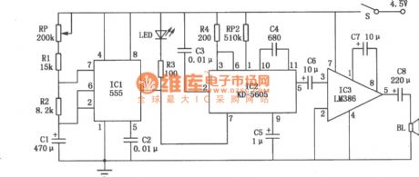
The Rat Exterminator E-cat Circuit is as shown. ICl is the time base IC NE555, the time control circuit is composed of the NE555, potentiometer RP, resistors Rl, R2 and capacitor Cl, this potentiometer controls the interval of the meows. IC2 is the mew IC KD-5605, this device save the mew. Close the switch S, power supplier charges Cl by the RP, Rl, R2, when the two ends voltage is 2/3 of the power supplier, pin-3 of ICl outputs the low-level current, LED light, at the same time IC2 works and output the meow signal, this signal is amplified by the IC3 to promote the loud speaker BL to send out the realistic meow. At the same time, discharge tube of the ICl connected to discharge power to the pin-7 of IC1. When two ends voltage of Cl drops to l/3 of power supplier, pin-3 of ICl output high-level current, LED turns off, IC2 stop working, mew stop too. The power supplier charges Cl by the RP, Rl, R2. (View)
View full Circuit Diagram | Comments | Reading(1142)
Electronic Video Switcher Circuit
Published:2011/4/24 22:21:00 Author:TaoXi | Keyword: Electronic Video, Switcher
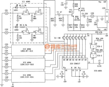
The Electronic Video Switcher Circuit is as shown:
(View)
View full Circuit Diagram | Comments | Reading(2835)
| Pages:2009/2234 At 2020012002200320042005200620072008200920102011201220132014201520162017201820192020Under 20 |
Circuit Categories
power supply circuit
Amplifier Circuit
Basic Circuit
LED and Light Circuit
Sensor Circuit
Signal Processing
Electrical Equipment Circuit
Control Circuit
Remote Control Circuit
A/D-D/A Converter Circuit
Audio Circuit
Measuring and Test Circuit
Communication Circuit
Computer-Related Circuit
555 Circuit
Automotive Circuit
Repairing Circuit