
Circuit Diagram
Index 1962
LED zero-beat indicating circuit
Published:2011/4/13 4:08:00 Author:Nicole | Keyword: LED, zero-beat indicating
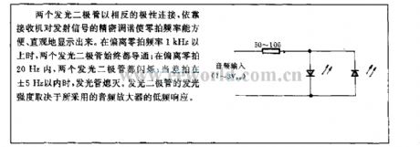
Two LEDs are connected with opposite polarity, it depends on the receiver accurate tune to the emission signal to display the zero-beat frequency conveniently and intuitively. When deviate beyond zero-beat frequency1kHz, two LEDs are conduction all the time; when deviate in zero-beat frequency 20Hz, two LEDs are flashing; when beat is in ±5Hz, LEDs are extinction. The luminous intensity of LED is determined by low-frequency response of the adopted audio amplifier. (View)
View full Circuit Diagram | Comments | Reading(528)
SC612 infrared ray remote control emission circuit
Published:2011/5/3 2:36:00 Author:May | Keyword: infrared ray, remote control emission
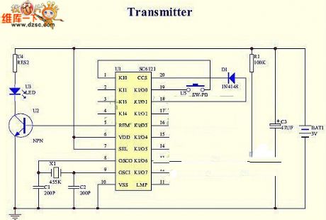
SC612 infrared ray remote control emission circuit is shown in the following picture:
(View)
View full Circuit Diagram | Comments | Reading(955)
The simplest voice FET amplifier board circuit
Published:2011/5/3 6:30:00 Author:Christina | Keyword: simplest voice, FET, amplifier board
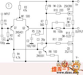
The Hitachi MOS FET amplification has the sound Of nature, and it is used by many of the top machine. The writer use the Hitachi 2SK399, 2SJ113 high-power tube (cheap and easy to purchase, common) to weld a minimalist amplifier, the circuit is simple that has only 23 components. This circuit has the good price and it is worth to recommend.
In the figure, Q1~Q3 use the 2N5401, 2N5551 (TV video amplifier tubes) as the differential and the main voltage amplification, because it has good frequency characteristics, good linearity and good effect. These amplification tubes can also choose the special fever tube, the sound quality can be further improved.Production requirements: the difference tube and the power tube should be matched to improve the open loop linear and improve the quality. HFEs' difference of Q1 and Q2 is ≤5% when the current is 0-5mA, higher HFE is better. The resistor uses the metal film resistor. In figure 1, you adjust the W1 to make the output mid-point be zero. This circuit can increase the output power by adding the output tube or increase the supply voltage. When it is ±36V, 8Ω, the output power is 50W. (View)
View full Circuit Diagram | Comments | Reading(2887)
Single power supply change into dual power supply circuit
Published:2011/5/3 6:19:00 Author:Christina | Keyword: Single power supply, dual power supply
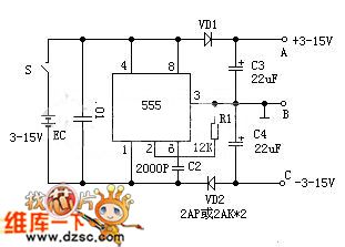
In the circuit, time base circuit 555 connected as an astable circuit (pin-3's output frequency is 20 KHz, duty cycle is 1:1). When the pin-3 is high level voltage, C4 is charged by the electric current; when the pin-3 is low level voltage, C3 is charged by the electric current. Because of the presence of VD1, VD2, the C3, C4 can be charged by the current, but can not be discharged, the maximum charge value is EC, if you connect the B to ground, you will get the +/-EC dual power at both ends of A, C. This circuit's output current is more than 50 mA.
(View)
View full Circuit Diagram | Comments | Reading(2683)
The Constant Temperature Attemperation Circuit of Film Flushing Liquor
Published:2011/5/3 6:23:00 Author:Christina | Keyword: Constant Temperature, Attemperation, Film Flushing Liquor
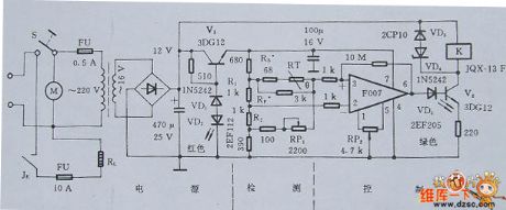
TheThe Constant Temperature Attemperation Circuit of Film Flushing Liquor is as shown in figure 1, this circuit contains three parts: detecting, controlling, and the power supply.
Figure 1. The Constant Temperature Attemperation Circuit of Film Flushing Liquor
Selection of the main components
To ensure the temperature adjustment accuracy, resistors R1 and R2 need to use the manganese bronze precision wirewound resistor with 0.05% accuracy; in addition, to ensure the uniformity of lotion's temperature, you need to install the promise speed mixer. The RL heating power is less than 2KW. (View)
View full Circuit Diagram | Comments | Reading(740)
Differential exposure meter circuit
Published:2011/5/3 6:18:00 Author:Christina | Keyword: Differential, exposure meter
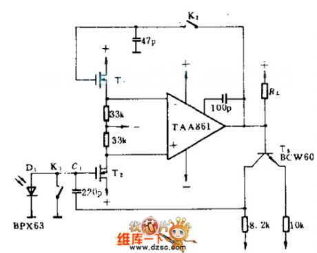
The BPX63 photodiode's sensitivityis 10mA/IX. This circuit ensures that the figure Location only affected by the useful light but not affected by the noise signal. When the circuit is under the low light condition, this circuit can collects a series of short pulse light rapidly. When the camera shutter is not open, K1, K2 closed, so the output of the operational amplifier tied back to its input port. At the beginning of the exposure, K1 and K2 open, the circuit produces more than 3000 times magnification. So the integration capacitor C1 charged by the photocurrent to make the output voltage changed by the time. When the output voltage is 1V, T3's base-emitter starts to conduct. When the C1 feeds back through T3, the RL stops, so the exposure stops, power supply is +/-3V.
(View)
View full Circuit Diagram | Comments | Reading(733)
555 Simple Linear Sawtooth Wave Generator Circuit
Published:2011/5/3 6:04:00 Author:Robert | Keyword: Linear Sawtooth Wave, Generator
As shown, after 555 triggering andfliping,the capacitor C generates the sawtooth waveby charging,and this wavecan be the scanningvoltage of the oscilloscope, but its linearity is not very well, so this circuit uses the constant current source instead of the timing resistor during themonostable and transient time, this can get the linear sawtooth wave. The linear ramp-up time is shown below.
(View)
View full Circuit Diagram | Comments | Reading(2119)
XTR106 Thermocouple Measuring Loop Circuit
Published:2011/5/3 6:48:00 Author:Robert | Keyword: Thermocouple, Measuring Loop
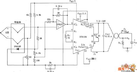
The circuit shown below is athermocouple measuring loop circuit which hasdiode cold-junction compensation with features of low offset, low drift. The noninverting amplifier is constituted by the OPA277, and use the noninverting amplifier's high input impedance to reduce thermocouple offset and loop drift. The 50Ω potentiometer is used for calibration, and the user can use itto adjust the noninverting input offset of the amplifier to change the K type thermocouple's output currentin the range of4mA to 20mAinits corresponding working temperature range.
(View)
View full Circuit Diagram | Comments | Reading(1396)
555 Square Wave And Sawtooth Wave Generator Circuit
Published:2011/5/3 7:15:00 Author:Robert | Keyword: Square Wave, Sawtooth Wave, Generator

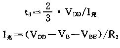
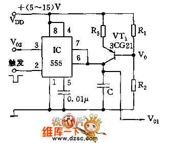
As shown, 555 and R2, C1, VT1 etc. make up a monostable trigger circuit, the difference from the general trigger is thatVT1,R1,R2,R3 make up a constant current source, to charge to C1 with constant current, whichmakes C1's charging voltage linearity good and has precise delay. The delay time td≈1.1R2C1. It is required the trigger pulse cycle time T>td. The output wave is shown as picture below. (a) is circuit. (b) is wave.
(View)
View full Circuit Diagram | Comments | Reading(1710)
Wien Bridge Sine-Wave Generator Circuit Composed of F007
Published:2011/5/3 20:24:00 Author:Sue | Keyword: Wien Bridge Sine-Wave Generator Circuit Composed of F007
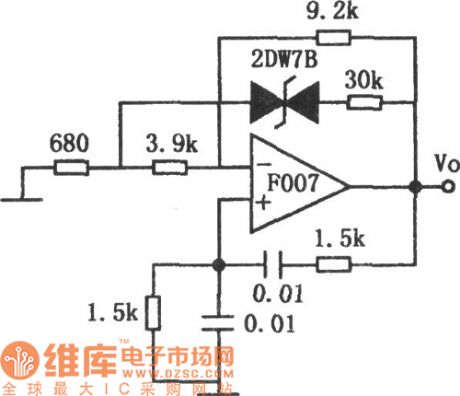
As seen in the figure is wien bridge sine-wave generating circuit. This circuit uses voltage stabilizing diode to stablize amplitude, and the oscillate frequency is 1kHz. If we replace the 1.5kΩ resistance with a coaxial duplex potentiometer, or change the capacitor value with a wave band switch, we can adjust the output frequency. The highest frequency of a circuit is decided by operational amplifier's frequency characteristic, while the low frequency terminal requires a larger resistance value, so the operational amplifier's input impedance should be as high as possible. In the voltage stabilizing diode branch, which is between the 680Ω and 3.9Ω resistance, there is a 30kΩ resistance to prevent the gain change from varying too quickly. If voltage stabilizing diode with soft breakdown characteristic is used, there will be less distortion, and the distortion rate can reach 0.5%. (View)
View full Circuit Diagram | Comments | Reading(938)
Low-Cost Wien Oscillator Circuit Composed of F007
Published:2011/5/3 20:24:00 Author:Sue | Keyword: Low-Cost, Wien, Oscillator
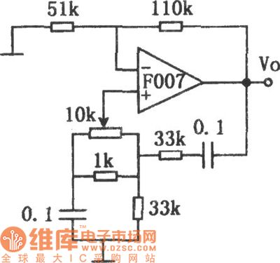
As seen in the figure is the low-cost wien oscillator circuit. On one hand, it can solve the problem of using expensive inductance coil in ordinary oscillatory circuit, on the other hand it can avoid the problem of using duplex potentiometer to adjust frequency in ordinary wien bridge oscillator. Ituses onlyone potentiometer to adjust fequency, so the cost is low. Despite of the narrow range of adjusting frequency,it is still useful when the frequency range is not large, and this circuit has a good stability. (View)
View full Circuit Diagram | Comments | Reading(515)
Battery Driving Temperature Sensor Circuit
Published:2011/5/3 5:02:00 Author:Felicity | Keyword: Battery Driving Temperature Sensor Circuit,
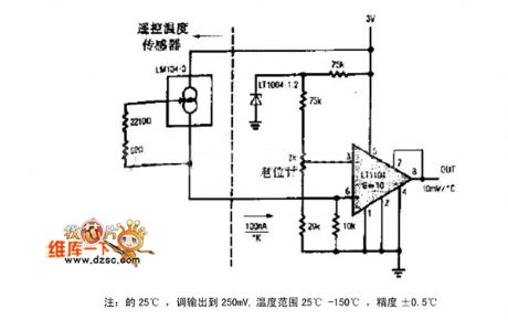
The picture above shows the battery temperature sensor circuit. (View)
View full Circuit Diagram | Comments | Reading(885)
NTJD4001N、NTJD4401N Internal Circuit
Published:2011/5/3 3:00:00 Author:Felicity | Keyword: Internal Circuit,
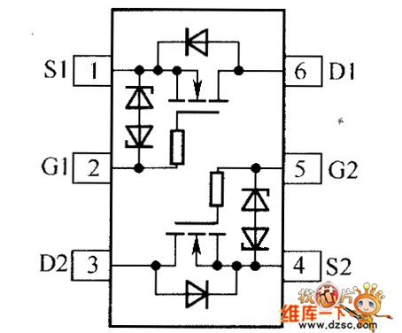
The picture above shows NTJD4401N、NTJD4401N Internal Circuit . (View)
View full Circuit Diagram | Comments | Reading(777)
H7N0310LM Internal Circuit
Published:2011/5/3 9:31:00 Author:Felicity | Keyword: Internal Circuit
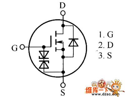
The picture above shows the H7N0310LM Internal Circuit. (View)
View full Circuit Diagram | Comments | Reading(411)
TDA8190 Power Amplifier Circuit
Published:2011/5/3 9:31:00 Author:Felicity | Keyword: Power Amplifier Circuit
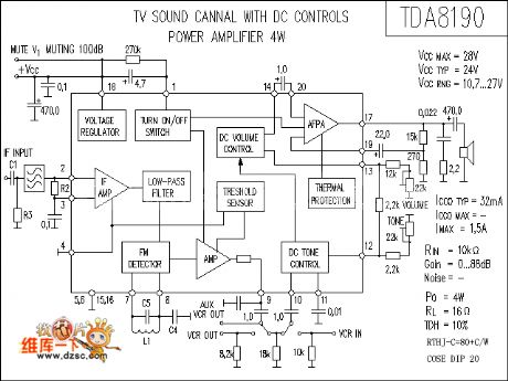
The picture above shows the TDA8190 Power Amplifier Circuit. (View)
View full Circuit Diagram | Comments | Reading(1504)
HAT1054R Internal Ciecuit
Published:2011/5/3 9:31:00 Author:Felicity | Keyword: Power Amplifier Circuit,

The picture above shows the HAT1054R Internal Circuit. (View)
View full Circuit Diagram | Comments | Reading(428)
Secure electronic firecracker circuit
Published:2011/5/3 8:25:00 Author:Christina | Keyword: Secure, electronic firecracker

The Secure electronic firecracker circuit is as shown in the figure. ICl is the KD-5601 integrated circuit which can issues the sound of firecracker. When you using the match to fire the electronic firecracker, the match's light acts on the photoresistor RG to let the resistance decreases rapidly, the transistor VTl gets into the conduction state, ICl starts to work because the positive pulse. The output signal of ICl is magnified by the composite pipe which is composed of the transistor VT2, VT3, and it promotes the loud speaker BL to send out the sound of firecracker. At the same time, three different colors of light-emitting diode LEDl ~ LED3 turn on too, and the light spreads to the top of the glass tube by the optical fiber. After a few seconds, the circuit automatically stops working. When you are debugging and change the resistance of the potentiometer RP to make the photoresistor RG has no light, the ICl stops working, IC1 works if there is light irradiation. You can adjust the resistor R4 to make the LED flashes with the sound of firecracker. Also if you adjust R5~R7, you can change the brightness of LEDl1~LED3.
(View)
View full Circuit Diagram | Comments | Reading(2484)
Electric water heater thermostat control circuit
Published:2011/5/3 9:16:00 Author:Christina | Keyword: Electric water heater, thermostat control
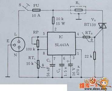
The electric water heaters always use the phase angle control method to control the temperature, that means the electric water heaters use the two-way SCR to control the heating element power's conduction angle of each half cycle. Greater the conduction angle is, longer the conduction time of each half cycle is, so the electric heating elements has the greater average power; otherwise the average power is smaller. This mode makes the load current's conduction and blocking more frequent to produce a large number of harmonics, these harmonics have great disturbance to other home appliances. Here I introduce the full cycle control method's water heater thermostat with automatic control circuit.
1 principle circuit
Figure 1 is the electric water heater thermostat control circuit. Because the RL's conduction and blocking happen in the moment of the voltage is over-zero, and the number of conduction and blocking per second is less than the phase angle control method, so even in the use of high-power electric equipments, there will not have a great interference.
Figure 1 Electric water heater thermostat self-control circuit
2 Selection of the main components
In order to facilitate the adjustment, the electric water heater thermostat self-control circuit uses the potentiometer which has linear resistance characteristics. RT1 uses the PTC thermistor after the line treatment, RT2 uses the 60℃ step-type PTC thermistor. VS is determined by the RL's power, and this circuit's RL is 2KW, the SCR should be equipped with heat sink. (View)
View full Circuit Diagram | Comments | Reading(4591)
voice control duplex wireless interphone circuit
Published:2011/5/3 9:55:00 Author:Christina | Keyword: voice control, duplex, wireless interphone
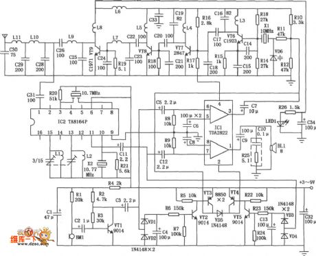
The wireless interphone is in the FM duplex mode, the operating frequency is 30MHz, it uses the voice control electronic switch, the circuit is simple, easy to use and saving energy. The operating voltage is 3 to 9V, the transmitting power is 1~5W.
The voice control duplex wireless interphone has two parts: receiving part and transmitting part (use the antenna matching network together), the circuit is as shown in figure. The transmitting part is composed of the microphone amplifier, electronic switch, oscillation and frequency circuits, incentive amplifier, power amplifier and the antenna matching network. The receiving part is composed of the antenna matching network, the FM receiving circuit, the electronic switch and the amplifier circuit.
(View)
View full Circuit Diagram | Comments | Reading(1478)
Passive driver amplifier circuit
Published:2011/5/3 18:56:00 Author:Christina | Keyword: Passive driver, amplifier
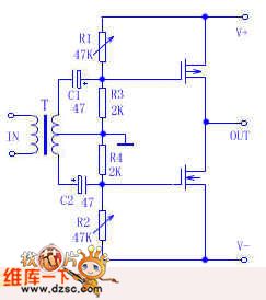
The author made a heterogeneous amplifier which is composed of the old radio's output transformer and two FETs, use this amplifier with the AL007 sound card, the effect is good. This is one kind of simple amplifier and it is suitable for the beginners to copy. The circuit is as shown. Signal from the sound card gets into the transformer T primary stage (the original radio's output transformer is used as the input transformer, the original secondary stage transformer is used as the primary stage transformer), this signal is boosted by the transformer and gets into the FET through capacitors C1 and C2, the FET enlarges this signal to drive the speaker. The trick of this circuit is: uses the passive components voltage amplifier stage. For the low input impedance, this device can be only used to continue the low output impedance's signal. Power supply can work in ±6V~±24V voltage condition and you just need to adjust R1, R2 to keep the 30mA quiescent current.
(View)
View full Circuit Diagram | Comments | Reading(891)
| Pages:1962/2234 At 2019611962196319641965196619671968196919701971197219731974197519761977197819791980Under 20 |
Circuit Categories
power supply circuit
Amplifier Circuit
Basic Circuit
LED and Light Circuit
Sensor Circuit
Signal Processing
Electrical Equipment Circuit
Control Circuit
Remote Control Circuit
A/D-D/A Converter Circuit
Audio Circuit
Measuring and Test Circuit
Communication Circuit
Computer-Related Circuit
555 Circuit
Automotive Circuit
Repairing Circuit