
Circuit Diagram
Index 1955
STV2116 color decoding and scanning signal processing integrated circuit diagram
Published:2011/5/5 1:57:00 Author:Ecco | Keyword: Color , decoding , scanning , signal , processing, integrated circuit
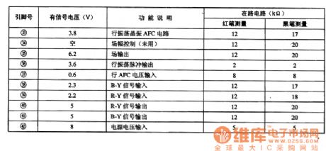
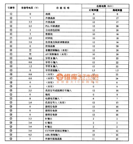
STV2116 is the color decoding and scanning signal processing integrated circuit produced by SGS-THOMSON company in French, it is widely used in various domestic and imported large screen color television sets, such as Skyworth, TCL and so on. 1. Features of functionSTV2116 IC is mainly composed of the clock oscillator circuit, automatic color elimination control circuit, data and clock interface circuit, the volume control circuit, the character BRG signal processing circuit, ribbon pass and notch adjustment circuit, the character blanking signal processing circuit, the luminance signal or video signal processing circuit, color signal processing circuit, small-field scanning line signal processing circuit and other ancillary functions circuit. 2. Pin functions and data STV2116 IC uses million inline package with 42 feet in double rows, the pin functions and data are listed in Table. STV2116 IC pin functions and data
(View)
View full Circuit Diagram | Comments | Reading(821)
Two LEDs alternately flashing circuit diagram controlled by digital integrated circuit
Published:2011/5/5 2:28:00 Author:Ecco | Keyword: Two, LED alternately, flashing , controlled , digital integrated circuit
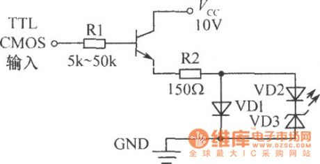
The circuit shown as the chart is controlled by TTL or CMOS digital integrated circuit, it will flash alternately by the transistor conduction to drive two LED lights. Different supply voltage can change the R and the regulation value of VD3 to meet the requirements of two alternately flashing. (View)
View full Circuit Diagram | Comments | Reading(585)
Power supply working status indication circuit
Published:2011/5/5 2:22:00 Author:Ecco | Keyword: Power supply , working status , indication circuit
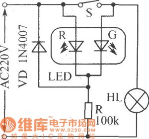
In the circuit shown as the chart, LED-R is used as a power indicator, LED-G is load HL (light) work status indicator. When the 220V AC electric supply is normal, LED-R emits red light. When switch S is closed, HL is lit, LED-G emits green light, then LED-R is also the lit, so when S is closed, the two-tone LED emits orange color.
(View)
View full Circuit Diagram | Comments | Reading(1440)
Tiny intensity light control switch circuit
Published:2011/5/2 6:32:00 Author:Nicole | Keyword: light control switch
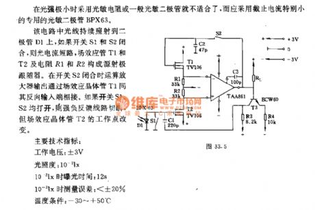
When the light intensity is tiny, it is unfit for adopting photosensitive resistance or general photodiode, it should use special photodiode BPX63 with small cut-off current.
In the circuit, the light constantly shines diode D1, if switches S1 and S2 is closed, then the photocurrent is short-circuited, the source emitter follower is composed of FETs T1 and T2, resistances R1 and R2. When switch S2 is closed, opertional amplifier output is connected to its inverting input terminal by FET T1. If switches S1 and S2 are all open, then the strong negative feedback is cut off, but the work point of FET T2 is changed.
Main technique target: work voltage: ±3V; illuminance: 0.01lx; the exposure time of 0.02lx: 12s; the measurement error of 0.01lx: < ±20%; temperature condition: -30~+50℃. (View)
View full Circuit Diagram | Comments | Reading(639)
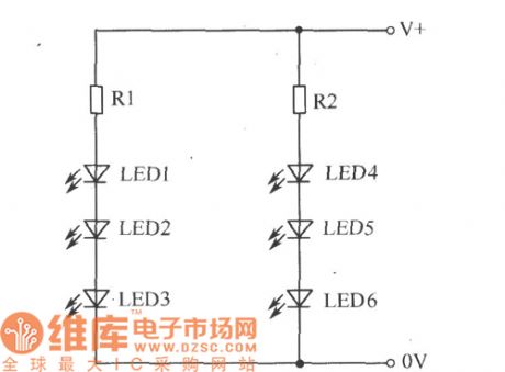
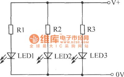
The driver circuit diagram with many LEDs
Published:2011/5/5 2:12:00 Author:Ecco | Keyword: driver circuit, many, LED
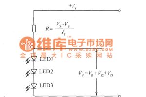
The LED connected in series can be driven by a current-limiting resistor:
The circuit can drive any number of LEDs:
The circuit uses the parallel method to drive a lot of LEDs:
(View)
View full Circuit Diagram | Comments | Reading(684)
CZG-GD-500 series UV flame sensor contour circuit
Published:2011/5/5 2:15:00 Author: | Keyword: CZG-GD-500series, UV flame sensor, contour
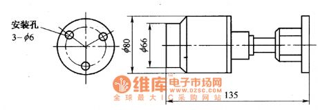
CZG-GD-500 series UV flame sensor is made with ultraviolet phototube, which works as the sensing device and has the characteristics of high sensitivity, anti-interference ability and wide monitoring function. It's applicable to fire alarm systems in inflammable and explosive places, and also can be used for boilers, furnaces flame failure warning. Its dimensions are as shown in the picture. (View)
View full Circuit Diagram | Comments | Reading(1288)
Optical control automatic rice distribution machine circuit
Published:2011/4/29 22:25:00 Author:Nicole | Keyword: optical control, rice distribution machine
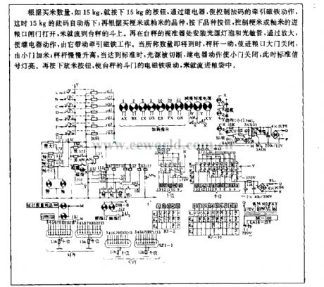
According to the quantity of purchased rice, such as 15kg, you can push 15kg button, to make the tractive magnet which controls the counter poise move, then the 15kg counter poise automatically falling; according to the kinds of japonica rice or indica rice, to push kinds button, it can control the food-importing port of japonica rice or indica rice gate open, then the rice flow to the funnel of platform scale. Fixing source bulb and light-sensive diode in the vane of platform scale, ater it is amplified, the relay will take action to drive tractive magnet work. When it is nearly the wanted quantity, the steelyard will close the food-importing port, the rice is added from the small gate; then the steelyard rises slowly, when it reaches the standard, the light source is cut off, relay closes the small gate, the standard singal light on. To push the released rice button, the electromagnet of platform scale's delivery gate pulls up, then the rice will flow into haversack. (View)
View full Circuit Diagram | Comments | Reading(672)
Inductive proximity sensor operation circuit
Published:2011/5/5 2:14:00 Author: | Keyword: Inductive proximity sensor, operation
Inductive proximity sensor operation circuit
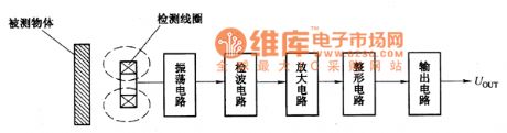
Proximity sensor is a kind of device which can perceive objects close to it . It uses sensibility of the displacement sensors to the objects nearby to identify objects and output switching signals. Therefore, proximity sensors are often referred to asproximity switches.
Inductive proximity sensor is a asproximity switch using vortex to percept objects . It consists of high-frequency oscillation circuit, detection circuit, amplifier, shaping circuit and output circuit, as shown in Figure 26-36. Perception sensor is as detection coil, which is an integral part of the oscillation circuit. In the work surface of the detection coil, there is an alternating magnetic field. When metal objects approach the detection coil, the metal objects will produce vortex and absorb the vibration energy, until vibration is reduced till to stop. And vibration and stop these two states will be output as switching signals.
(View)
View full Circuit Diagram | Comments | Reading(1847)
Opto-electrical range acquisition circuit
Published:2011/4/24 5:05:00 Author:Nicole | Keyword: opto-electrical range acquisition circuit
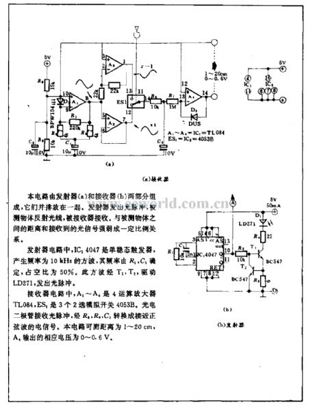
This circuit is composed of transmitter(a) and receiver(2), they are put side by side. Transmitter emits optical pulse, the light is reflected by the measured object and then received by the receiver. It has proportional relationship to the distance of measured object and the degree of received optical singal.
In transmitter circuit, IC14047 is monostable trigger, it produces 10kHz square wave, the frequency is decided by R1, C1, the duty ratio is 50%. By T1, T2, this square wave drives LD271 to emit optical pulse. (View)
View full Circuit Diagram | Comments | Reading(656)
Opto-electrical adjustment circuit
Published:2011/4/22 21:36:00 Author:Nicole | Keyword: opto-electrical adjustment circuit
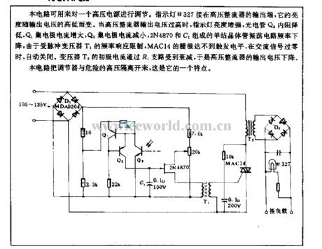
This circuit can be used to adjust a high voltage power supply. Indicator light #327 is connected to the output terminal of high voltage rectifier, its brightness changes in relation to output voltage. When the output voltage of high voltage rectifier is too high, the brightness of indicator light increases, the resistance of phototube Q3 reduces, Q1 collector current increases, Q2 collector current decreases, the frequency of unijunction transistor oscillation circuit composed of 2N4870 and C1 drops, limited by the frequency response of pulse transformer T1, MAC14 grid can not reach the trigger level, when the AC singal is zero passage, the light turns off automatically. The primary current of transformer T2 is reduced by R1 branch, then the output voltage of high voltage rectifier drops.
The feature of this circuit is to isolate the regulator from the dangerous high voltage. (View)
View full Circuit Diagram | Comments | Reading(653)
Platinum resistance signal conditioner ADT70 interior circuit diagram and typical application circuit diagram
Published:2011/4/21 21:40:00 Author:muriel | Keyword: Platinum resistance signal conditioner
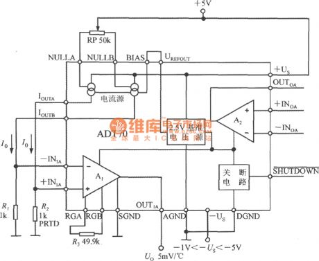
As shown is Internal circuit diagram and typical application circuit of platinum resistance signal conditioner ADT70. There are five parts of the chip:1. 2.5V reference voltage source2. two balanced output type current source3. instrument amplifier A14. reserve amplifier A25. turn-off circuit
In the picutre it uses the double-power supply. When -Us is at least -1V, it can measure the temperature below 0°C. The SGND、AGND and DGNA are all grounding. When SHUTDOWN non-connected the DGND, the ADT70 is turned-off; Without the end, it should be connected the +Us. When +5V power supply go through the potentiometer, it will supply the current source power. The 2.5V reference voltage sourceprovides bias to the current source. Two current source respectiveprovide exciting current for nominal resistance R1 and platinum resistance R2, The voltage difference of R2 and R1 is used for the input voltage of instrument amplifier. After adjust the gain of the instrument amplifier, It can obtain the output voltage Uo which vary directly as the measured temperature, final it send to the digital voltmeter that will show the measured temperature value. The resistence of R1 is 1KΩ. R2 is Pt1000 platinum resistance, its nominal resistence is 1kΩ below 0°C. RP is tone balance potentiometer. R3 is gain resistance of instrument amplifier.
(View)
View full Circuit Diagram | Comments | Reading(1077)
Regulated power supply circuit diagram used VMOS as switching element
Published:2011/4/8 2:38:00 Author:Nicole | Keyword: regulated power supply, switching element
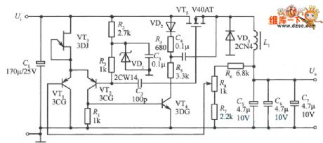
As shown, it is a power supply circuit used VMOS as switching element. VT5 is VMOS power transistor, the switch adjustment element of power supply; L1is the energy storage inductor; VD3 for the freewheeling diode; VT3 for the FET, as the constant current source of VTl, VT2, to provide the emitter with lmA constant current; Cl is the input filter capacitor; C5, C6, C7 is the output filter capacitor.
It is determined by the relative voltage of the two base to turn on VTl or VT2 first. If the base potential of VT1 below VT2, the VTl on, VT2 off; on the contrary, the VTl off, VT2 on. The base potential of VT2 is decided by resistances R2, R3 and voltage regulator diode VD1, it is a constant; and base potential of VTl is obtained from the output voltage through the resistor R6C R, and derived from the potentiometer R8, the output voltage can be changed by adjusting potentiometer R8.
In order to reduce the power consumption of switch regulator VT5, to improve its turning speed, the circuit adopts bootstrap network which composed of R5, C4. When VT5 is off, the source potential is 0V, the input voltage charge to C4 through diode VD2 resistor R4, so that the voltage on C4 is close to the input voltage. When VT5 is on, the source potential rise, as there is sufficient voltage on the capacitor C4, so that the diode VD2 off, by this time, the voltage on R5 is close to 2 times the input voltage, so VT5 turn on more quickly. At this point even if the input voltage is low, the circuit also can be flipped. The role of C2, C3 is to make VT1, VT2 flip quickly, then to improve the speed of switching.
(View)
View full Circuit Diagram | Comments | Reading(1436)
741 op-amp device as the I/V converter circuit
Published:2011/5/4 2:30:00 Author:Christina | Keyword: op-amp device, I/V converter
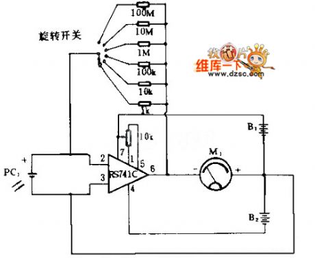
The 741 op-amp deviceas the I/V converter circuit is as shown. Current of PC1 can be considered that all through the feedback resistor, the current flowing through the ammeter equal to 741C output voltage divided by the internal resistance of meter, and this current has relationship with the solar cells current. by whirling the switch and inserting resistances with different values the circuit can provide 6 stages metering range. When you access the 100MΩ resistance profile, it has the highest sensitivity. Power meter's sensitivity is 0 to 1mA.
(View)
View full Circuit Diagram | Comments | Reading(2212)
Automatic water supply circuit
Published:2011/5/4 18:53:00 Author:Christina | Keyword: Automatic, water supply
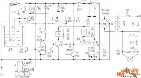
The water tower automatic protection circuit is as shown: household low-power water pumps has no protection measures, so it is easy to leak, and the electric motor is damaged because there is water, or the automatic control circuit is not work to cause the water overflow. The author adds the automatic protection circuit to this circuit, and realizes the water tower unmanned management, this circuit is simple and safe:
Figure Automatic water supply circuit (View)
View full Circuit Diagram | Comments | Reading(1578)
FET logic probe circuit
Published:2011/5/4 18:55:00 Author:Christina | Keyword: FET, logic probe
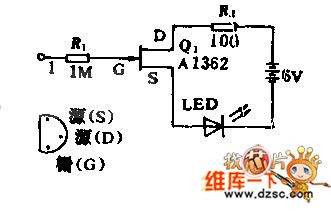
Field-effect transistor with high input impedance can make the LED light when the input port appears logic 1, and it will not produce the load effect on the monitored circuit.
(View)
View full Circuit Diagram | Comments | Reading(971)
Automatic name-call telephone circuit
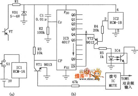
Published:2011/5/4 19:00:00 Author:Christina | Keyword: Automatic, name-call telephone

By this circuit, you can make the telephone call names automaticly, this means when the phone rings, this circuit will answer the phone automaticly, and ask who are you ? , if the opposite side people say: I'm looking for × × × × , the telephone will amplify the answer signal and send out the signal by speaker. This circuit is simple and reliable, and does not increase the load of communication network, you just need to change a line of the speaker. IC3 uses the 3 seconds language integrated circuit or the language processor. When you installing this circuit, you should keep the questioning speaker aim at or close to the machine microphone.
(View)
View full Circuit Diagram | Comments | Reading(886)
wireless remote control phone lock circuit
Published:2011/5/4 22:28:00 Author:Christina | Keyword: wireless, remote control, phone lock
The key of the telephone lock uses the remote controller form, the remote controller is in charge of the owner or office leader, the lock actuator is installed in the telephone. Only if you press the button on the remote controller, the lock will be opened and then you can dial. But the three numbers public phones such as the 119 , 110 , 120 .etc are not limited by this lock, also the answer. This circuit do not need the external power supply or mechanical lock, so it has some practical value.
(View)
View full Circuit Diagram | Comments | Reading(1203)
AC welding machine energy-saving controller circuit
Published:2011/5/4 22:29:00 Author:Christina | Keyword: AC, welding machine, energy-saving controller
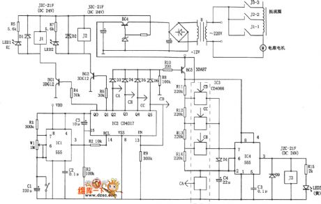
The AC welding machine has the intermittent working mode, the no-load power consumption in the interval can be several hundred watts. The AC welding machine energy-saving controller circuit is as shown. This circuit turns off the power in the interval, and turns on the power if you want to weld.
(View)
View full Circuit Diagram | Comments | Reading(6092)
869~894MHz Narrow-Band Amplification Circuit Composed Of RF2320/2360
Published:2011/5/5 0:58:00 Author:Robert | Keyword: 869~894MHz, Narrow-Band, Amplification
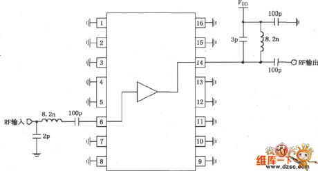
The picture shows the 869~894MHz narrow-band amplification circuit composed of RF2320/2360. The RF signal inputs from the 6 foot and outputed from the 14 foot through the amplifier. The 6 foot is coupling with internal amplifier, so it needs to add a 100pF blocking coupling capacitor (make up input matching networks with 8.2nH inductor). The 14 foot is output port and can be added to power Vdd through matching inductor. If users only consider aboutthe drift current, it only needs to add one choke coil.
(View)
View full Circuit Diagram | Comments | Reading(571)
RF2360 Linear General Purpose Amplifier Pin Circuit
Published:2011/5/5 0:58:00 Author:Robert | Keyword: Linear, General Purpose Amplifier, Pin
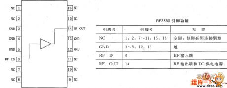
The RF2360 is a general purpose, low-cost, high-linearity RF amplifier IC, and is manufactured on an advanced gallium arsenideheterojunction bipolar transistor (HBT) process. It has been designed for using as an easily cascadable 75Ω gain block with a noise figure of less than 2dB. Gain flatness is better than 0.5dB from 5MHz to 1000MHz, and high linearity makes this part ideal for cable TV applications. Other applications are include IF and RF amplification in wireless voice and data communication products which operating in frequency bands up to 1000MHz. The device is self-contained with 75Ω input and output impedances providing less than 2:1 VSWR matching. RF2360 is featured in a SOP-16 squaredbatwing package, and its pinout is shown in the picture below.
(View)
View full Circuit Diagram | Comments | Reading(708)
| Pages:1955/2234 At 2019411942194319441945194619471948194919501951195219531954195519561957195819591960Under 20 |
Circuit Categories
power supply circuit
Amplifier Circuit
Basic Circuit
LED and Light Circuit
Sensor Circuit
Signal Processing
Electrical Equipment Circuit
Control Circuit
Remote Control Circuit
A/D-D/A Converter Circuit
Audio Circuit
Measuring and Test Circuit
Communication Circuit
Computer-Related Circuit
555 Circuit
Automotive Circuit
Repairing Circuit