
Circuit Diagram
Index 50
Alto air conditioning circuit diagram
Published:2013/12/9 20:54:00 Author:lynne | Keyword: Alto air conditioning circuit diagram,
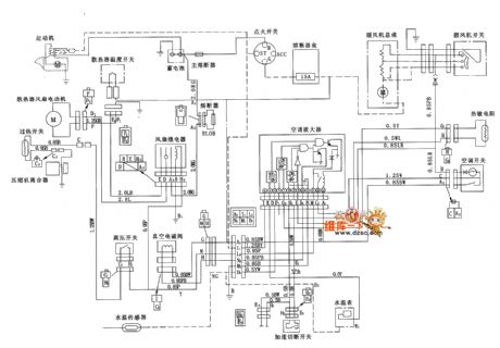
Alto air conditioning circuit diagram is shown below:
(View)
View full Circuit Diagram | Comments | Reading(1249)
Citroen TU3F2K engine schematics
Published:2013/12/9 20:52:00 Author:lynne | Keyword: Citroen TU3F2K engine schematics,

Citroen TU3F2K engine circuit diagram is shown below:
(View)
View full Circuit Diagram | Comments | Reading(970)
Citroen TU5JPK engine schematics
Published:2013/12/9 20:49:00 Author:lynne | Keyword: Citroen TU5JPK engine schematics,

Citroen TU5JPK engine circuit diagram is shown below:
(View)
View full Circuit Diagram | Comments | Reading(1144)
Mercedes-Benz 190E electric windows circuit diagram
Published:2013/12/9 1:37:00 Author: | Keyword: Mercedes-Benz 190E electric windows circuit diagram,
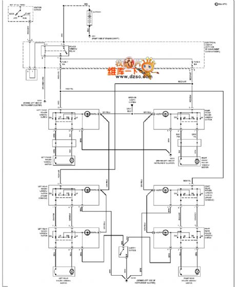
Mercedes-Benz 190E electric windows circuit diagram is shown below:
(View)
View full Circuit Diagram | Comments | Reading(3048)
Mercedes-Benz 190E electric mirrors Diagram
Published:2013/12/9 1:34:00 Author: | Keyword: Mercedes-Benz 190E electric mirrors Diagram,
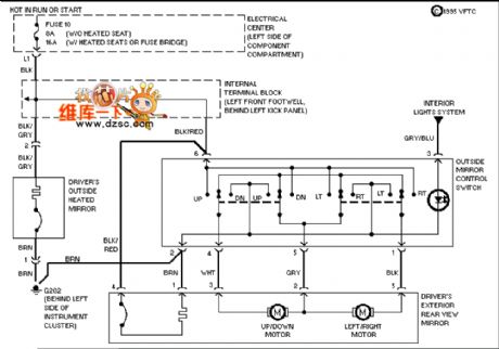
Mercedes-Benz 190E electric mirrors circuit diagram is shown below:
(View)
View full Circuit Diagram | Comments | Reading(2226)
Mercedes-Benz 190E power supply circuit
Published:2013/12/9 1:28:00 Author: | Keyword: Mercedes-Benz 190E power supply circuit,
Mercedes-Benz 190E power supply circuit are as follows:
(View)
View full Circuit Diagram | Comments | Reading(996)
Mercedes-Benz 190E seat adjustment circuit diagram
Published:2013/12/9 1:25:00 Author: | Keyword: Mercedes-Benz 190E seat adjustment circuit diagram,
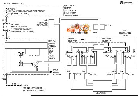
Mercedes-Benz 190E seat adjustment circuit diagram is shown below:
(View)
View full Circuit Diagram | Comments | Reading(1388)
Mercedes 190E dashboard schematics
Published:2013/12/9 1:17:00 Author: | Keyword: Mercedes 190E dashboard schematics,
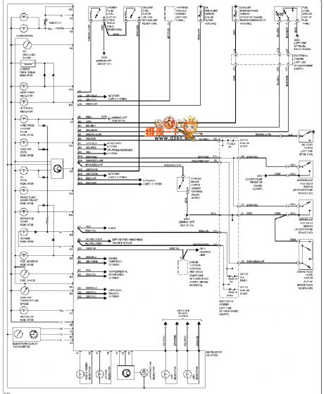
Mercedes 190E dashboard diagram is shown below:
(View)
View full Circuit Diagram | Comments | Reading(1470)
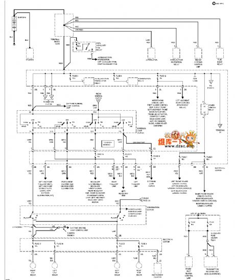
Mercedes-Benz 190E external light circuit diagram
Published:2013/12/8 21:13:00 Author:lynne | Keyword: Mercedes-Benz 190E external light circuit diagram,
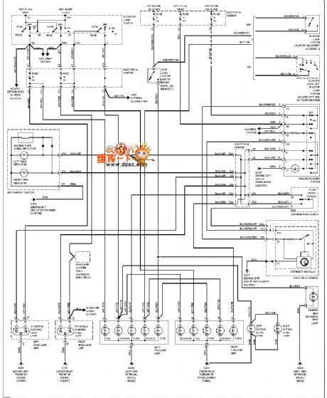
Mercedes-Benz 190E external light circuit diagram is shown below:
(View)
View full Circuit Diagram | Comments | Reading(2047)
Mercedes-Benz 190E GND Ground Distribution Diagram
Published:2013/12/8 21:16:00 Author:lynne | Keyword: Mercedes-Benz 190E GND Ground Distribution Diagram,
Mercedes-Benz 190E GND Ground distribution diagram is shown below:
(View)
View full Circuit Diagram | Comments | Reading(1501)
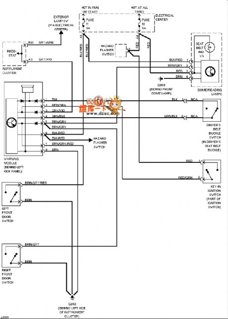
Mercedes-Benz 190E headlight circuit (no DRL)
Published:2013/12/8 21:18:00 Author:lynne | Keyword: Mercedes-Benz 190E headlight circuit (no DRL),
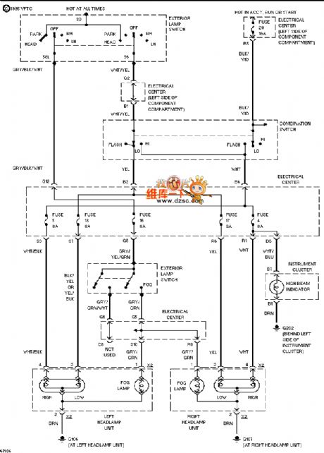
Mercedes-Benz 190E headlight circuit (no DRL) as follows:
(View)
View full Circuit Diagram | Comments | Reading(1181)
Mercedes-Benz 190E seat heater circuit diagram
Published:2013/12/8 21:19:00 Author:lynne | Keyword: Mercedes-Benz 190E seat heater circuit diagram,
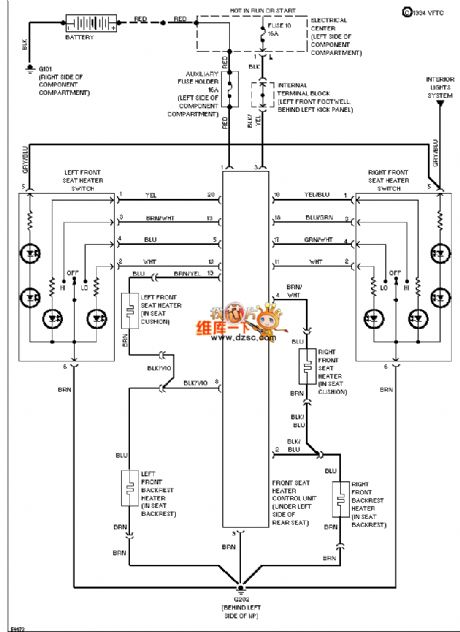
Mercedes-Benz 190E seat heater circuit diagram is shown below:
(View)
View full Circuit Diagram | Comments | Reading(1530)
Mercedes-Benz 190E Schematic defogger
Published:2013/12/8 20:52:00 Author:lynne | Keyword: Mercedes-Benz 190E Schematic defogger,
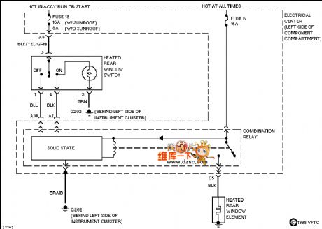
Mercedes-Benz 190E defogger circuit diagram is shown below:
(View)
View full Circuit Diagram | Comments | Reading(1212)
Solar Charger Monitor Circuits
Published:2013/12/5 19:56:00 Author:lynne | Keyword: Solar Charger Monitor Circuits
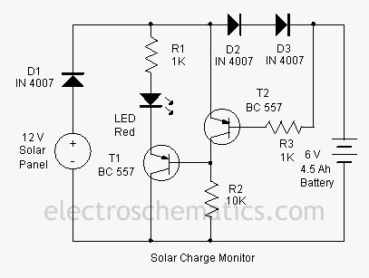
This add on circuit can be attached to the solar charger to see whether the battery is charging or not. It lights a Red LED to indicate that the battery is not accepting charge. It gives a warning indication if there is any loose connection with the charger and battery.
The Solar charger monitor circuit uses two PNP transistors T1 and T2 to give a warning indication if there is any loose connection with the charger and battery. If the connection is intact and current is flowing into the battery, diodes D2 and D3 forward bias and drops around 1.2 volts. This forward voltage drop across the diodes causes T2 to conducts. The collector current from T2 keeps the base of T1 high and it remains off. Red LED connected to the emitter of T1 remains off indicating that current is flowing to the battery and the connections are intact. When there is any break in the connecting cables or any loose contacts in the terminals, no more current passes and D2 and D3 reverse biases. This turns off T2 and T1 conducts .LED lights indicating that battery is not getting charging current.
Solar Charger Monitor Circuit Diagram
(View)
View full Circuit Diagram | Comments | Reading(1366)
Battery Monitor Circuits
Published:2013/12/5 19:47:00 Author:lynne | Keyword: Battery Monitor Circuit
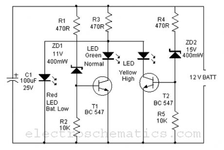
Here is a simple Battery Monitor circuit for a quick check of 12 volt Lead-Acid Battery. Battery charge should be constantly monitored to increase the life of the battery. Overcharge as well as under charge will reduce the battery life. The terminal voltage of the Lead Acid battery should be with in the range of 12.5 to 13.5 volts. If the battery voltage reduces below 10 volts for long period, battery will not accept any charging current. Similarly if the terminal voltage exceeds above 14 volts, battery will be destroyed.
The circuit is a Zener controlled transistor switch lighting three LEDs Red, Green and Yellow to show battery states like Low, Normal and High. When the battery voltage is less than 11 volts, Zener diodes ZD1 and ZD2 cease to conduct and Red LED only lights indicating low battery condition. If the voltage is between 12 volt and 14 volts, Zener diode ZD1 forward bias and T1 conducts. The Green LED connected to the collector of T1 lights indicating normal voltage. If the battery voltage exceeds 15 volts, Zener diode ZD2 also conducts and T2 forward bias. This lights Yellow LED indicating over charge. Thus the following indications can be obtained.
Battery Monitor Circuit Diagram (View)
View full Circuit Diagram | Comments | Reading(1976)
Simple Battery Monitor Circuits
Published:2013/12/5 19:43:00 Author:lynne | Keyword: Simple Battery Monitor Circuits

This simple Battery Monitor lights an LED when the battery voltage drops below 9 volts. It is an ideal add on circuit to monitor the charge level in 12 volt miniature batteries used in Portable devices or Alarm systems. In the standby state, LED remains off.
Working of the circuit is based on the base biasing of transistor T1. When the battery voltage is above 9 volts, base-emitter voltage will be same. This keeps both T1 and LED off. When the battery voltage reduces below 9 volts due to consumption, base voltage of T1 drops while its emitter voltage remains same since capacitor C1 is fully charged. At this stage, base of T1 becomes positive and T1 turns on. Capacitor C1 discharges through the LED and it lights.
Simple Battery Monitor Circuit (View)
View full Circuit Diagram | Comments | Reading(1067)
Battery Level Monitor Circuits
Published:2013/12/4 21:39:00 Author:lynne | Keyword: Battery Level Monitor Circuit
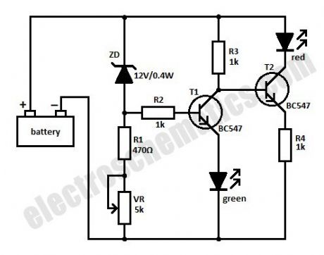
This simple battery level monitor circuit can indicate the charging process in 12 Volt Lead Acid battery or Tubular battery. The status of LED indicates whether the battery is accepting charge or not. It also indicates the full charge condition.
The battery monitor circuit can be incorporated in any battery charger like 6, 9, 12 volt etc. The only change needed is replacement of the Zener ZD with appropriate value. That is for 6 volt charger use 6.1 volt Zener and for 9 volt charger it should be 9.1 volt Zener.
Battery Level Monitor Circuit
The circuit is based on the switching of two NPN transistors (BC547) to drive the corresponding LED. Zener diode ZD is connected to the base of T1 so as to switch on T1 when the Zener conducts. This happens only when the battery voltage is above 12 volts. Green LED lights when the battery voltage is normal or battery attains full charge. Resistor R1 and Preset VR adjust the base bias of T1 for smooth switching. When T1 conducts, base of T2 will be pulled to ground and T2 turns off and Red LED extinguishes.
When is connected to the battery before charging the LED indications will be
If the battery voltage is above 12 volts (that is the normal terminal voltage of 13.8), Zener conducts and Green LED lights and Red LED remains off.If the battery voltage is below 12 volts, Zener remains non conducting and Green LED remains off and Red LED lights.When the battery is connected to the charger, and if the battery is accepting charge, Green LED goes off and Red LED remains on. When the battery attains full charge, Green LED lights and Red LED goes off. If the battery is not accepting charge, Green LED never lights, even after the prolonged charging. This indicates that the battery is not attaining the normal terminal voltage above 12 volts. (View)
View full Circuit Diagram | Comments | Reading(2354)
Voltage Stabilizer Circuits with LDR (Photoresistor)
Published:2013/12/4 21:28:00 Author:lynne | Keyword: Voltage Stabilizer Circuit with LDR (Photoresistor)
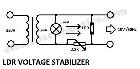
Voltage Stabilizer Circuit with LDR (Photoresistor)
This is a very interesting a.c. voltage stabilizer that uses a LDR or photoresistor to stabilize an alternating current (AC).If the voltage increases then the brightness of the light bulb increases too and the LDR’s resistance will decrease. If the potentiometer is properly adjusted then the AC voltage will stay constant.
The optimal adjustment of potentiometer is done experimental, feeding the circuit with a variable ratio transformer, which can simulate variations of voltage network.
LDR voltage stabilizer circuit schematic
(View)
View full Circuit Diagram | Comments | Reading(1180)
Automatic Lawn Light with LDR Circuit
Published:2013/12/4 21:25:00 Author:lynne | Keyword: Automatic Lawn Light with LDR
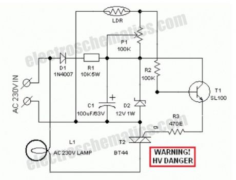
Circuit of a compact and true solid-state automatic lawn light is described here.The circuit can be used to switch on incandescent garden light bulbs at desk and switch off them at dawn. A 10 mm encapsulated light dependent resistor (LDR) here works as the twilight detector.
The whole circuit can be housed in a very small plastic cabinet.For powering the circuit AC 230V household supply is needed. With a little skill and patience, you can easily modify this circuit to drive a number of white LED strings, instead of the incandescent bulb load at the output.
When ambient light is normal, transistor T1 is reverse biased by the low resistance of LDR. Multi-turn palstic trimpot P1 sets the detection sensitivity. If ambient light dims, transistor T1 turns on to drive the triac T2. Now the lamp load at the output of T2 energises.When the ambient light level restores, circuit returns to its idle state and light(s) switched off by the circuit.
Working voltage for the circuit is derived directly from the AC supply input through components D1, R1, D2 and C1. This obviates the requirement of a bulky and noisy step-down transformer.
If you wish to operate the light bulb(s) on a little reduced power,just replace the triac T2 with a suitable silicon controlled rectifier (SCR). This may give a long life to the incandescent load. Finally, the LDR should not be mounted to receive direct sunlight. It may be mounted at the top of the enclosure, pointing to the sky say southwards.
LDR Lawn Lights Circuit Schematic
(View)
View full Circuit Diagram | Comments | Reading(1990)
LDR Flashing LED Circuit
Published:2013/12/3 20:47:00 Author:lynne | Keyword: LDR Flashing LED Circuit
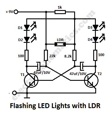
In this flashing led lights circuit, the LDR or photoresistor is connected in such way that when the light intensity varies it will influence the flashing frequency and the brightness of the LEDs. T1, T2 = BC547, BC548, BC549 (any NPN transistor).
You can arrange the LEDs D1 to D4 in cross in order to obtain interesting effecs. The whole flashing led circuit is powered from a 9 volt battery and can be built small enough so it will fit in a matchbox.
Schematic of Flashing Lights with photoresistor
(View)
View full Circuit Diagram | Comments | Reading(2192)
| Pages:50/2234 At 204142434445464748495051525354555657585960Under 20 |
Circuit Categories
power supply circuit
Amplifier Circuit
Basic Circuit
LED and Light Circuit
Sensor Circuit
Signal Processing
Electrical Equipment Circuit
Control Circuit
Remote Control Circuit
A/D-D/A Converter Circuit
Audio Circuit
Measuring and Test Circuit
Communication Circuit
Computer-Related Circuit
555 Circuit
Automotive Circuit
Repairing Circuit