
LED and Light Circuit
Index 20
Automatic Light Switch Circuit
Published:2012/9/24 4:12:00 Author:muriel | Keyword: Automatic, Light Switch
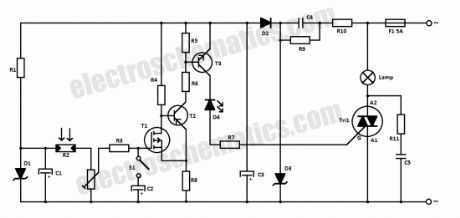
This light sensitive automatic light switch circuit is intended to be connected at the main 220V supply. The circuit will connect a 220V lamp when at the nightfall and disconnects it in the morning light. The switching is made without a relay in order to avoid problems with the electric arc and noise caused by inductance coil and contacts.The automatic light switch is powered from the 220V network through R10, C4, D3, D2 and C3. A reference voltage source, D1, feeds with 8.2 V the circuit for measuring light, R2-P1. At lower light intensity, LDR’s resistance, R2, increases and therefore the P1 voltage falls, so will fall the gate-source voltage of FET’s T1.
When the switch S1 is closed, R3-C2 time constant makes that the gate voltage of T1 to vary slower then R2 resistance. This is necessary to prevent the circuit reaction at rapid changes of ambient light intensity.
Automatic light sensitive switch circuit schematic
T1, T2, R4, R5, R6 and R8 forms a trigger Schmitt. Normally, T1 is open and T2 is blocked. When the gate voltage of the FET goes below a certain level, T2 starts to conduct and so does T2 which will provides the necessary gate current to boost the triac Tri1 in order to connect the load (220V lamp).
Caution! Because there are many points that are connected at 220V it is essential to apply a good insolation. Do not work on the circuit when is connected to the mains.
Components listR1 = 2.2KR2 = LDRR3 = 150KR4 = 15kR5 = 10kR6 = 27kR7 = 560ΩR8 = 1.2kR9 = 1.2MR10 = 470ΩR11 = 100ΩC1 = 4.7µF/16V tantalumC2 = 47µF/16VC3 = 1000µF/16VC4 = 470nF/250V~(630V)C5 = 100nF/630VD1 = 8.2V zenerD2 = 1N4001D3 = 15V/1W zenerD4 = LEDT1 = BS250T2 = BC557BT3 = BC547BTri1 = TIC226MF1 = 5A?
18 Responses to “Automatic Light Switch Circuit”
(View)
View full Circuit Diagram | Comments | Reading(1995)
Touch light dimmer circuit
Published:2012/9/24 4:11:00 Author:muriel | Keyword: Touch, light dimmer
With IC SLB0586A from Siemens you can build a simple touch light dimmer circuit that will allow you to adjust the lamp intensity. Together with a TIC206D triac, it enables smooth regulation of light intensity from a bulb of 10W – 400W. A coil of 100µH/5A is required to suppress switching noise.The voltage supply is obtained through R2, C2, D1 and C3 and is about 5.3V below the network potential. The touch sensor that is used to drive the IC is connected at pin 5 through two 4.7MΩ resistors, R5 and R6, in order to ensure user security.
In the adjustable touch lamp schematic we can see three selection connection , for selecting one of three modes of the IC. When the B connection is used, the light will always be ON at the last level that we used. With A or C connection the light will be ON at the minimum intensity. With B or C, the purpose of regulation is reversed with each use.
When the sensor is touched for a short period of time (50 – 400 ms), the lamp will be ON or OFF. If the sensor is touched for a longer period of time it will start the regulation process.
Schematic of the adjustable light with touch sensor
Warning! This touch light dimmer circuit has some points where lethal 220V is present, please do not try this project if you are not qualified. (View)
View full Circuit Diagram | Comments | Reading(1655)
Simple Arduino LED projects
Published:2012/9/24 4:02:00 Author:muriel | Keyword: Arduino, LED

In this article I will add some simple Arduino LED projects starting with basic ones like how to turn on an LED, blinking, and more. Every step will have the code, the schematic, photos of the project and sometimes a video tutorial.
Let’s start with the simplest led project which consists in turn on an LED. You can use an external one or use the one soldered on the board (pin 13).Turn ON an LED Sketch This is a very simple arduino project where a led is turned on by setting the pin 13 as output, then write it with a high value, in our case that means that pin 13 will deliver 5 volts.void setup() {
pinMode(13, OUTPUT); // set pin 13 as output
digitalWrite(13, HIGH); // set pin 13 as high or 1
}
void loop() {
// left empty
}
If you want to turn on more leds then set other pins as OUTPUT and HIGH.Next lets blink some leds.
Blinking leds sketchvoid setup() {
pinMode(13, OUTPUT); // set pin 13 as output
pinMode(12, OUTPUT); // set pin 12 as output
}
void loop() {
digitalWrite(13, HIGH); // set pin 13 as high or 1
digitalWrite(12, LOW); // set pin 12 as low or 0
delay(1000); // wait 1000 ms
digitalWrite(12, HIGH); // set pin 13 as high or 1
digitalWrite(13, LOW); // set pin 12 as low or 0
delay(1000); // wait 1000 ms
}
“Knight Rider” effect sketchint del=100; // sets a default delay time
void setup() {
// initialize the digital pins as outputs:
for (int i = 2; i<=8 ; i++) {
pinMode(i, OUTPUT);
} // end of for loop
} // end of setup
void loop() {
for (int i = 2; i<=8; i++) { // blink from LEDs 2 to 8
digitalWrite(i, HIGH);
delay(del);
digitalWrite(i, LOW);
}
for (int i = 7; i>=3; i--) { // blink from LEDs 8 to 3
digitalWrite(i, HIGH);
delay(del);
digitalWrite(i, LOW);
}
}
Fading LED sketchint ledPin = 9; // LED connected to digital pin 9
void setup() {
// nothing happens in setup
}
void loop() {
// fade in from min to max in increments of 5 points:
for(int fadeValue = 0 ; fadeValue <= 255; fadeValue +=5) {
// sets the value (range from 0 to 255):
analogWrite(ledPin, fadeValue);
// wait for 30 milliseconds to see the dimming effect
delay(30);
}
// fade out from max to min in increments of 5 points:
for(int fadeValue = 255 ; fadeValue >= 0; fadeValue -=5) {
// sets the value (range from 0 to 255):
analogWrite(ledPin, fadeValue);
// wait for 30 milliseconds to see the dimming effect
delay(30);
}
}
More arduino led projects will be added soon. Thank you!?
2 Responses to “Simple Arduino LED projects”
(View)
View full Circuit Diagram | Comments | Reading(1558)
Simple and Useful LED circuits
Published:2012/9/24 4:02:00 Author:muriel | Keyword: LED
Due to the advantages like low voltages, long life, cheap, reliable, fast on-off switching etc, the LED’s are used in many applications. The various applications of LED are,
All kinds of visual displays i.e. seven segment displays and alpha numeric displays. Such displays are commonly used in the watches and calculators.
In the optical devices such as optocouplers.
As on-off indicator in various types of electronic circuits.
Some LED’s radiate infrared light which is invisible. But such LED’s are useful in remote controls and applications like burglar alarm.
Other simple applications of LED are :
Sometimes you need to know which wire/node is positive polarity and which wire/node is negative polarity.The LED as a polarity indicator circuit is show in above diagram. In the diagram as you can see two LED’s are placed in opposite directions so when one LED is ON the other LED will be OFF. I have used Red and Green LED’s. ?When node A is positive green LED glows while when node B is positive, Red LED glows. This indicates polarity of the input d.c voltage .
The above shown circuit is LED as continuity tester. This circuit is used for checking continuity of cables, connectors and switches. When A and B terminals are shorted, the LED glows due to battery connected inside indicating the presence of continuity.
To prevent the reverse biased destruction rectifier diode D is used. The presence of voltage is instead of ?series resistor, a capacitor is used whose reactance Xc which is ( 1/2 πfC )Ω limits the current. Advantage of using capacitor is that it does not consume any power hence total power dissipation is less.
When fuse is working, it provides short circuit path bypassing LED circuit. So LED is OFF. If fuse opens the line voltage drives the LED through capacitor and thus LED glows. Thus blown fuse condition is indicated.
Not only these there are many useful applications of diode.What do you say..?? ??
8 Responses to “Simple and Useful LED circuits”
(View)
View full Circuit Diagram | Comments | Reading(2190)
Simple Solar Lamp circuit
Published:2012/9/21 3:26:00 Author:Ecco | Keyword: Simple, Solar Lamp
Here is the simple solution to make an automatic Solar powered lamp. It automatically switches on two high power White LEDs in the evening and stays on for 6 hours using a 6 volt 4.5 Ah rechargeable battery.A 12 volt solar panel is used to charge the battery during day time. The battery is connected to the input line through the NO and Common contacts of the relay. Diodes D1 and D2 drops 1.4 volts and charge indicator LED uses 1.8 volts. Relay also drops some voltage so that around 8 volts will be available for charging the battery. The high value (4700uF) Capacitor C1 act as a “buffer” for the clean switching of the relay and also prevents “relay clicking” when the input voltage reduces momentarily.
Simple Solar Lamp Circuit diagram
During day time, the solar panel generates 12 volt DC which makes the relay active and the NO (Normally Open) contact makes connection with the common contact. This completes the current path to the battery. Two 1 Watt power LEDs are connected to the NC (Normally Connected) contacts of the relay. When the relay energize, the NC contact breaks and LEDs do not get power. Resistor R2 ( 18 Ohms 1 Watt) drops the LED current to 330 mA. The LEDs are rated 350 mA at 3.6 volts. With 3 volts and 250 mA current, these LEDs can give adequate brightness.
1 Watt Power LED
In the evening, current from the solar panel stops and relay de – energize. At the same time, the NC contact of the relay gets power from the battery through the common contact and LEDs turn on. Theoretically, the battery can power 12 hours with 350 mA current, but the battery voltage and current reduces drastically. So it is better to turn off the lamp after 5 or 6 hours using the switch S1.Use a small 6 volt 100 Ohms PCB relay to make the lamp unit compact. The Solar Lamp circuit including the relay can be enclosed in a small box. If a reflector is fixed behind the White LEDs, intensity of light can be increased. Use jack and socket to connect the solar panel with the circuit.?
16 Responses to “Simple Solar Lamp circuit”
source: electroschematics.com (View)
View full Circuit Diagram | Comments | Reading(2425)
Power LED Lamp
Published:2012/9/21 3:25:00 Author:Ecco | Keyword: Power , LED Lamp
Here is a High power White LED lamp circuit that gives ample light in a room. It is an energy saving lamp and consumes very little power to give sufficient light. The lamp is directly powered from AC hence it is compact and easy to fix inside the switch board box.The Power LED Lamp circuit uses 1 Watt White LED as the light source. Luxeon type high watt LEDs are now available. It is rated 3.6 volts and consumes maximum 350 milli amperes current. To get sufficient brightness of the LED, more than 200 mA current is required. The AC power is dropped by three 105K (1uF) AC capacitors to low voltage AC. Three capacitors (C1through C3) are connected in parallel to increase current so around 210 mA current will be available.
The low volt AC is then rectified by the bridge comprising D1 through D4 and made ripple free by C4. Since the LED voltage is 3.6 V, Zener diode is used to regulate the DC to a safer level. Capacitor C5 act as a buffer to store current to give maximum brightness to the LED. Resistor R1 removes stored current from the AC capacitors when the circuit is unplugged and resistor R2 protects the circuit from transients and inrush current.
Power LED Lamp Circuit diagram
1 Watt Power LED
Caution: It is important to note that this circuit can give a lethal shock if handled carelessly. Most points are at mains potential, so that take utmost care while handling. Do not construct this if you are not experienced in handling AC circuits. Do not troubleshoot or test when it is connected to mains.?
39 Responses to “Power LED Lamp”
source: electroschematics.com
(View)
View full Circuit Diagram | Comments | Reading(2294)
High Volt LED Flasher
Published:2012/9/21 3:24:00 Author:Ecco | Keyword: High Volt, LED Flasher
Here is a Flasher circuit that directly derives power from AC to give brilliant flashes at the rate of one flash per second. It uses a Diac as the main element to flash the LED through current pulses.
230 Volt AC is reduced to 50 volt DC by the dropping capacitor C1 and is rectified by the full wave bridge D1 through D4.Resistor R1 removes stored current from C1 when the circuit is unplugged and resistor R2 protect the circuit from inrush current.
The main element in the circuit is the Diac DB3.It is a semiconductor device that acts as a Voltage-Controlled switch. If a low voltage is applied to the Diac, it remains as an open switch passing little current. All diacs have a break down voltage VBO which is between 28 volts and 36 volts. If the applied voltage is above the minimum VBO, the Diac enters into the” Negative Resistance” region and heavy current passes through it. Diacs are commonly used in pulse generator circuits for driving SCRs and Triacs.
In the circuit, Diac forms a Relaxation Oscillator along with capacitor C2.When the capacitor C2 gets current, it charges slowly through R3.When the voltage in C2 increases above the VBO of Diac( 28 V), Diac conducts and current passes through the LED and it turns on. At the same time C2 discharges and the Diac becomes non conducting. Again C2 charges and the process repeat. This gives brilliant flashes at the rate of one per second.
High Volt LED Flasher Circuit
Values of R3 and C2 determine the flash rate. With 100K resistor and 22 uF capacitor, the frequency will be around 1Hz. Value of the LED current limiter R4 is also important to determine the flash rate. Higher value above 220 Ohms will reduce the flash rate since the capacitor takes more time to discharge.If the current through LED is too high, increase the value of R4 to 1.5 K and adjust the flash rate by reducing the value of R3.
Caution: This circuit is extremely dangerous because there is no galvanic isolation from mains. Most nodes are at mains lethal potential and hence dangerous. Do not try to construct this circuit, if you have no experience in handling high voltage circuits.?
One Response to “High Volt LED Flasher”
source: electroschematics.com (View)
View full Circuit Diagram | Comments | Reading(1656)
Outdoor Garden Solar Lights circuit
Published:2012/9/20 21:06:00 Author:Ecco | Keyword: Outdoor Garden, Solar Lights
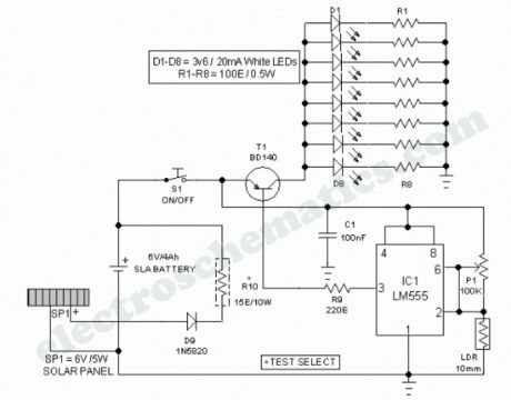
This Outdoor LED Solar Garden Lights project is a hobby circuit of an automatic garden light using a LDR and 6V/5W solar panel. During day time, the internal rechargeable 6 Volt SLA battery receives charging current from the connected solar panel through polariy protection diode D9 and current limiting resistor R10. If ambient light is normal, transistor T1 is reverse biased by IC1 (LM555).
LED Solar Lights Circuit Schematic
Here IC1 is wired as a medium current inverting line driver, switched by an encapsulated light detector (10mm LDR). Multi-turn trimpot P1 sets the detection sensitivity. When ambient light dims,transistor T1 turns on to drive the white LED string (D1-D8). Now this lamp load at the output of T1 energises. Resistors R1-R8 limits the operating current of the LEDs. When the ambient light level restores, circuit returns to its idle state and light(s) switched off by the circuit.Assemble the Outdoor Solar Lights circuit on a general purpose PCB and enclose the whole assembly in a transparent plastic box. Drill suitable holes on the top of the encloure to mount the mini solar panel (SP1) and the light sensor (LDR), and in front for fitting power switch (S1) and the sensitivity controller (P1).Fix the battery inside the cabinet using a double-sided glue tape/pad. Finally, the LDR should not be mounted to receive direct sunlight. It must be mounted at the top of the enclosure, pointing to the sky say southwards. This circuit is very simple. So interested and experienced hobbyists can alter/modify the whole circuit as per their own ideas without any difficulty (Just try a 6V relay with T1 to drive more number of LED strings)?
27 Responses to “Outdoor Garden Solar Lights circuit”
Source: electroschematics.com (View)
View full Circuit Diagram | Comments | Reading(3723)
Earth Fault Indicator circuit
Published:2012/9/20 21:05:00 Author:Ecco | Keyword: Earth Fault, Indicator
This circuit indicates the integrity of wiring connections. It shows all the mains connections – Phase, Neutral and Earth connections – are intact or not. The circuit is too small and can be housed in a three pin plug case.
Earth Fault Indication Circuit Diagram
The circuit is directly connected to mains to monitor the status of the connections. Earth connection is a must in domestic wiring to bleed current to the earth if the metal body of a device is accidentally touched with the phase line. This circuit indicates
1. Red and Green LEDs ON Phase, Neutral and Earth OK2. Red and Green LEDs OFF Phase or Neutral Break / Power failure3. Red LED ON Phase and Neutral OK3. Green LED OFF Earth line break
The circuit gets power supply through C1 and R3. AC Capacitor C1 reduces the high volt AC to a safer level through capacitive rectance. Resistor R3 limits the inrush current and R4 gives discharge path for the stored current in C1 when the circuit is unplugged. Zener diode ZD regulates the voltage to a safer level to protect T1 when it is off. Voltage across ZD will be a square wave by the working of C1 and the voltage level depends on the breakdown value of zener (9 volts). When a potential of 230 volt is present between the phase and neutral lines, T1 turns on during the negative half cycle of AC and Green LED lights indicating that Earth connection is intact. This is because the base of T1 will be biased by the potential difference between the phase line and earth. If the earth connection is not intact, T1 will not get base bias and it remains off. Red LED lights during the positive half cycle of AC due to the potential difference between the phase and neutral lines.Enclose the circuit in a 3 pin plug and connect points A, B and C to the phase, neutral and earth pins respectively. Plug it into the 3 pin socket to test the wiring.
Warning The circuit is kept at mains lethal potential. Do not touch any parts to avoid lethal shock. Do not construct this circuit unless you are experienced in handling High volt AC.?
16 Responses to “Earth Fault Indicator circuit”
Source: electroschematics.com
(View)
View full Circuit Diagram | Comments | Reading(1693)
Blinker circuit
Published:2012/9/20 20:58:00 Author:Ecco | Keyword: Blinker
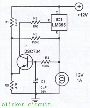

The blinker circuit design is made using the LM395 IC. This IC is a short-circuit proof power transistor with special characteristics. This is sometimes called a “super transistor”. LM395 is used in this circuit as an alarm blinker for cars.
12 volts Blinker circuit diagram
The blink frequency is determined by the R4/C1 combination which is dimensioned to give approximately one blink per second. To achieve lower frequencies, increase the value of C1. To achieve faster blink freq decrease the value of C1. The circuit cand drive 12 volts lamps. The maximum power delivered is 12 watts. The power transistor T1 must be heatsinked. Two PCB desing are available: one for TO-3 package and one for the TO-220 package.
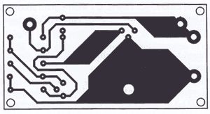
LM395 TO-3 Blinker PCB Layout
LM395 TO-220 Blinker PCB desing
?
One Response to “Blinker circuit”
(View)
View full Circuit Diagram | Comments | Reading(2321)
Speaker balance indicator circuit
Published:2012/9/20 20:58:00 Author:Ecco | Keyword: Speaker balance , indicator
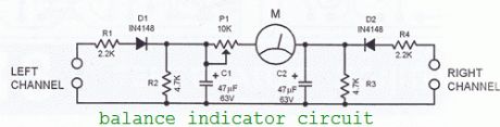
You may use this speaker balance calibrating circuit when using a stereo amplifier, there are many possible mechanical problems that may influence the amplifier’s output performance. The usual culprit is the mechanical potentiometers which are not rarely unsync in their stereo resistance pads. This results to unbalanced volume levels on the audio channels. Most good stereo units have a balance control to compensate for this imbalance.In using this balance indicator circuit, its left and right input channels are connected to the corresponding speaker outputs of the amplifier. Identical signals are then fed to the amplifier’s stereo inputs. When a signal of exactly the same amplitude is coming out from both speaker outputs, the meter M of the speaker balance circuit will stay at its zero setting. The meter M is a type with a zero setting at the middle of the scale. This enables one to see at first glance when one channel is louder than the other channel
Calibrating the speaker balance indicator circuit
Inject a signal in one channel and set the amplifier’s volume to maximum.While doing this, turn the potentiometer P1 until the meter swings to end of the scale in the direction of the channel.
Balance indicator circuit diagram
(View)
View full Circuit Diagram | Comments | Reading(1532)
Aquarium Led Lighting circuit
Published:2012/9/20 20:55:00 Author:Ecco | Keyword: Aquarium , Led Lighting
This colorful back led aquarium lights gives natural appearance to the Aquarium tank. The Aquarium Led Lighting circuit automatically turns on at sunset and gives changing White, Blue and Green color display to make the aquarium attractive. In the morning the aquarium led light turns off.The aquarium led light circuit uses LDR as light sensor for automatic switching of the circuit. During day time LDR has very low resistance so that IC1 remains stand by. In the night, LDR offers high resistance and the reset pin 12 of IC1 becomes low. This activates IC1. CD4060 is a binary counter with ten outputs. The outputs of IC become high one by one based on the frequency of counting determined by C1, R1 andR2. In the aquarium led light circuit, strings of LEDs are connected to the collector of switching transistors T1 through T3.
When the IC triggers, oscillations starts and the output Q6 turns on after 5 minutes and stays on for another five minutes to light Blue LEDs. After 10 minutes Q7 output becomes high and Green LED turns on. They remain on for 10 minutes. After half time, Blue LEDs also turn on. This gives a mixture of Blue and Green colors for 5 minutes. After 20 minutes Q9 output becomes high and White LEDs turn on. They remain on for 20 minutes. During this period, Blue-White, Green-White and Blue-Green-White color combinations develop. This gives beautiful color display to the background of the Aquarium tank.
Aquarium LED Lights Circuit diagram
Note: Keep LDR in a position at which it illuminates in day light but dark in night.?
30 Responses to “Aquarium Led Lighting circuit”
Source: electroschematics.com
(View)
View full Circuit Diagram | Comments | Reading(2170)
Telephone Status Indicator circuit
Published:2012/9/20 20:55:00 Author:Ecco | Keyword: Telephone Status, Indicator
This simple circuit tells you about the status of phone such as Line OK, Dialing and Call attended. It also has a lock facility to block outgoing calls keeping the incoming calls as usual. This prevents misuse of telephone. The circuit uses only a few components to do all these jobs. The circuit is directly connected to the telephone lines and no power supply is needed. In the On Hook state, the telephone lines have around 48 volts which reduces to 12 volts in Off Hook state. More over the line polarity changes during dialing and two way speech. Capacitors C1 reduce the line voltage to a safer level for the operation of LEDs. When the phone is Off Hook, Red LED lights to indicate that the lines are OK. When a call is dialed, Red LED blinks to indicate the dialing status. When the remote person attends the call, Green LED lights indicating that the call is attended.
Telephone Status Indicator Circuit diagram
A simple Toggle switch is provided as Lock. It can be replaced with an electrical lock with key. When the switch is in Off position, outgoing calls will be blocked but the telephone receives incoming calls as usual.
Electrical Lock
?
2 Responses to “Telephone Status Indicator circuit”
Source: electroschematics.com
(View)
View full Circuit Diagram | Comments | Reading(1326)
Low cost Pilot Lamp
Published:2012/9/20 20:53:00 Author:Ecco | Keyword: Low cost , Pilot Lamp
This is the simple way to connect an LED in the Mains to use it as a pilot lamp. It takes little current compared to a neon lamp. It can power low efficiency as well as high efficiency LEDs including White and Blue LEDs.The pilot lamp circuit is straight forward. A rectifying diode IN4007 (1A) is connected in series with the phase line. The rectified voltage is reduced to low volt by the resistor R1. Capacitor C1 filters some ripples and act as a buffer to provide continuous supply to the LED as the AC waveform swings. Resistor R2 determines the brightness of LED. With 1.5 K resistor, adequate brightness can be obtained.
Low cost Pilot Lamp Circuit
Important Note The pilor lamp circuit is directly connected to mains and hence at lethal potential. Do not touch or troubleshoot when it is connected to mains.?
8 Responses to “Low cost Pilot Lamp”
Source: electroschematics.com (View)
View full Circuit Diagram | Comments | Reading(1227)
Low Current Flasher circuit
Published:2012/9/19 21:50:00 Author:Ecco | Keyword: Low Current , Flasher
This is a low current flasher consumes only a few Micro amperes current and lights a high bright LED day and night for more than one year. This can be used in switch boards, key stand etc to locate them easily. Unlike other LED flashers, it uses the current from the capacitor to light the LED. With a 9 volt battery, the LED flashes more than one year.
IC1 is designed as a simple oscillator using only one gate. The LED is placed in the discharge path of capacitor C1.Capacitor C1 charges through D1 and R1 and discharges through the LED and R2. Power consumoption depends on the values of R1 and C1. With higher values LED shows low brightness but power consumption will be less.
Low current Flasher Schematics
One Response to “Low Current Flasher circuit”
(View)
View full Circuit Diagram | Comments | Reading(1360)
LED Searchlight Circuit
Published:2012/9/19 21:38:00 Author:Ecco | Keyword: LED Searchlight
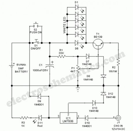
This LED searchlight comprises a sealed maintenance-free (SMF) battery, constant voltage battery charger, six high efficiency white LEDs and a LED light level control circuit.White LEDs (D1-D6) gets power supply from the 6V battery through on/off switch S1 (Switch S2 can be used for momentary power switching). Transistor T1 and associated components forms a light level control circuit. With the help of the linear potmeter (P1), user can adjust the intensity of the LED light output.
The search light can be recharged by connecting an external ac mains adaptor (12V/1A) to its charger input (J1). Internal battery charger circuit is built around the popular three pin fixed regulator LM7806(IC1). Red LED (D11) works as a charge mode indicator.
LED Searchlight Circuit Schematic
?
One Response to “LED Searchlight Circuit”
Source: electroschematic.com (View)
View full Circuit Diagram | Comments | Reading(1876)
Ornamental LED circuit
Published:2012/9/19 21:25:00 Author:Ecco | Keyword: Ornamental LED
Here is a simple LED flasher for decoration purpose. The High bright LEDs flashes alternately giving a brilliant colour display. The circuit is a simple Astable multivibrator using two NPN transistors T1 and T2.The circuit works on the principle of charging and discharging of capacitors C1 and C2. Current from the positive of battery flows through first set of LEDs D1-D5 to the collector of T1 through resistor R1.Resistor R1 limits current through the LEDs to protect them. The current through R1 and LEDs charge capacitor C1. It then discharges through the base of T2 and resistor R4. This gives base current to T2 and it conducts. As a result second set of LEDs D6-D10 lights.As the Capacitor C1 discharges completely, T2 turns off. LEDs D6-D10 also turns off.
The same thing happens in the other side also. This gives alternate flashing of LEDs.Thus the flashing effect is produced through the switching of T1 and T2 by the charge from capacitors.Flashing rate can be changed by changing the value of R3,R4 or C1,C2. If 500K preset is used in the place of R3/R4, flashing rate can be varied.
Ornamental LED Circuit
Source: electroschematic.com (View)
View full Circuit Diagram | Comments | Reading(1335)
Multi pattern Lamps
Published:2012/9/19 21:25:00 Author:Ecco | Keyword: Multi pattern Lamps
Multipattern serial lamps are now available at very low cost. These china make serial lamps circuit gives 8 pattern lighting like Combination, In Wave, Sequential, SLO-GLO, Chasing / Flashing, Slow-Fade, Twinkle/Flash, Steady On patterns etc. The same circuit can be used to drive four 40-60 Watts AC bulbs to decorate X mas stars.
The circuit is directly connected to AC lines. The PCB has a COB( Chip On Board) with a programmed ROM chip that generates multi patterns. The patterns can be automatic or can be selected through a push switch. The same chip can directly drive four 40-60 watts bulbs to decorate the Xmas stars. All the eight patterns will be generated in the bulbs giving an elegant display.
Multipattern Lamps Circuit
How to connect1.Open the circuit board box and remove the PCB.
2. There will be 5 wires on one side and 2 wires on the opposite side of PCB.
3. The 2 wires are for AC lines (Phase and Neutral). This can be used either way round.
4. Out of the 5 wires on the other side, 4 wires are for lamps and the last one for Neutral.
5. Remove the wires and solder 4 colored wires for lamps and a green / black wirefor neutral.
6. Connect 2 Red wires for Phase and Neutral.
7. Solder 2 wires at the contacts of the switch soldered in the PCB and connectthe wires to a Push-to-On switch to select patterns.
8. Enclose the wired PCB in a shock proof case and connect the Lamps as shown inthe diagram.
9. Connect an AC plug to the wires for Phase and Neutral.
10. Do not use bulbs above 60 watts.
Caution: The circuit is extremely dangerous since its PCB is at mains lethal potential. Do not try the circuit if you are not experienced in handling 230 volt AC. Connect the circuit to AC lines only after enclosing it in a shock proof case. Do not touch or trouble shoot when the PCB is in the open condition.
Author and Electroschematics.com will not have any responsibility to causality, if the circuit is mishandled.?
One Response to “Multi pattern Lamps”
Source: electroschematic.com
(View)
View full Circuit Diagram | Comments | Reading(1238)
DIY Solar Birdhouse Light
Published:2012/9/19 21:24:00 Author:Ecco | Keyword: DIY, Solar Birdhouse Light
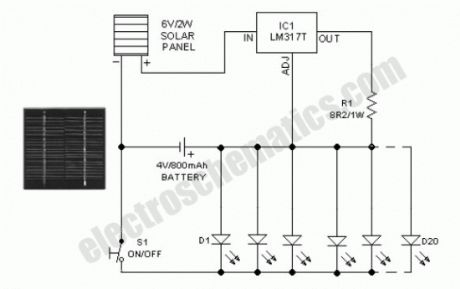
This solar birdhouse light is an economical circuit of a mini solar lighting system circuit is presented here. At the heart of the circuit is a mini 6V/2W solar panel. Here, this solar panel is used to charge a 4V/800mAh rechargeable battery through a charge current limiter circuit built around an adjustable 3-pin regulator LM317T (IC1). Resistor R1 sets the output current. The lighting circuit comprising 20 white LEDs are directly powered the battery. Swich S1 is a simple on/off switch. Assemble the circuit on a small PCB and enclose in a suitable cabinet. Fix the solar panel on the top of the cabinet and power switch and LEDs on the front side.Specification of a typical 6V/2W solar panel:
Maximum Power (Pm) :2W
Working Voltage (Vmp):9V
Working Current (Imp) :220mA
Open Circuit Voltage (Voc) :10.5V
Power Tolerance:-3% to +5%
Assuming a 6 hour sunlit day, a 2 watt panel (near 150mA current set by the regulator IC1+R1) will pump about 900mAh into the battery. Solar charging current can be reduced by increasing the value of R1 ,say from 8.2 Ohm to 10 Ohm.
Solar Birdhouse Circuit Schematic
?
11 Responses to “DIY Solar Birdhouse Light”
Source: electroschematic.com
(View)
View full Circuit Diagram | Comments | Reading(3005)
Flashing Lights Circuit
Published:2012/9/18 21:39:00 Author:Ecco | Keyword: Flashing Lights
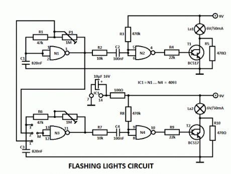
This flashing lights circuit can be used as beacon. The assembly consists basically of two blinking steps that commands two light bulbs. With the help of P1 you can adjust the flashing frequency between some limits.There are 2 parts for the circuit, the second one works the same way as the other but with the help of a wire bridge or a switch you can choose different operating modes.A bridge between M and 3 means: 2 independent blinks.If there is a bridge between M and 2, then the lamps lights alternatively with a frequency that can be adjusted with P1. And finally there is one more possibility for M and 1, where the lamps blinks at the same time.
The flashing lights circuit works with voltages between 3V and 15V.The lamps voltage must be 2/3 of working voltage. R5 and R10 are chosen so that the lamps are about to light.
Flashing Lamp Lights Circuit Schematic
3 Responses to “Flashing Lights Circuit”
(View)
View full Circuit Diagram | Comments | Reading(1459)
| Pages:20/72 1234567891011121314151617181920Under 20 |
Circuit Categories
power supply circuit
Amplifier Circuit
Basic Circuit
LED and Light Circuit
Sensor Circuit
Signal Processing
Electrical Equipment Circuit
Control Circuit
Remote Control Circuit
A/D-D/A Converter Circuit
Audio Circuit
Measuring and Test Circuit
Communication Circuit
Computer-Related Circuit
555 Circuit
Automotive Circuit
Repairing Circuit