
LED and Light Circuit
Index 7
Solar Powered Reading Lamp
Published:2013/3/7 3:01:00 Author:Ecco | Keyword: Solar, Powered Reading Lamp
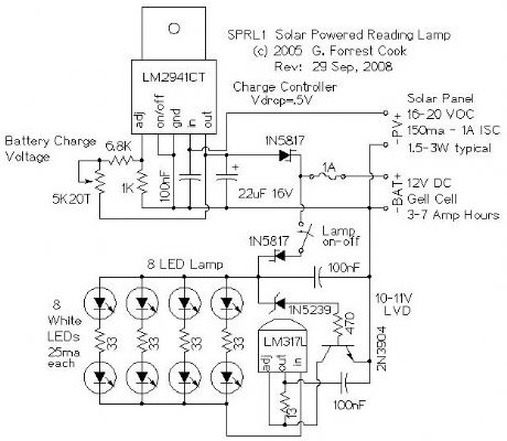
The goal of this project was to produce a self contained reading lamp that could be used by students in developing countries for reading at night. The circuit can be used for a wide variety of lighting applications.
The reading lamp consists of a small solar panel, a standard UPS style lead acid battery, and an LED circuit board. The circuit board contains a low power solar charge controller (regulator), a set of 8 white LEDs, a switch, an LED current regulator, and a low voltage disconnect circuit. The circuitry will insure a long battery life by preventing over charging and excessive discharging. The circuit was designed to work with lead acid batteries, it should also work with a string of 10 NiCd cells. Both the charge controller and LED regulator circuits can be used independently for other applications.
Newer VW and Audi automobiles come with small solar panels for keeping the battery charged in the sales lot. These panels are available on eBay for around $15 and are a perfect fit for this project. An inexpensive 12V 7AH lead acid gell-cell battery that is typically found in a computer UPS is also a good fit for this circuit. Be sure to use a new battery.
(View)
View full Circuit Diagram | Comments | Reading(1464)
Solar Powered Night Light
Published:2013/3/7 2:59:00 Author:Ecco | Keyword: Solar , Powered , Night Light
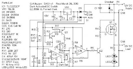
An LM2941CT low dropout voltage regulator is used as the solar charge regulator. The IC passes solar power to the rechargeable battery until the charge voltage setting is reached, after that point, the regulator limits the charge current to maintain the charge voltage setting (float voltage). The 1N5817 Schottky diode between the LM2941CT and the battery + terminal prevents battery from discharging through the charge controller at night.
The on/off/On At Dark switch selects the mode of operation. When On, battery power is routed to the lamp circuit, but not to the CDS photo sensor, simulating a dark room. The LED lamp turns on. When in the On At Dark position, battery power goes to the lamp circuit and the CDS photo sensor, the LED lamp turns on when the CDS sensor is dark.
The CDS photo sensor is in series with a 2M potentiometer and a 100K resistor. The signal at TLC27L4 pins 2 and 12 changes voltage with varying light levels on the CDS photo sensor. The left two TLC27L4 op-amp sections form a window comparator circuit with hysteresis. The outputs of the two comparators are fed to the right two TLC27L4 op-amp sections through two 1N4148 diodes.
The right two TLC27L4 op-amp sections form a set/reset flip-flop circuit. The flip-flop turns on at a particular darkness, then turns off at a brighter level due to the circuit's hysteresis. This operation lessens the tendency for the circuit to flicker on and off at the trigger point. The TLC27L4 op-amp is a rail-to-rail device, if you substitute another op-amp, make sure it is capable of rail-to-rail operation.
The on/off signal from the flip-flop is sent to the upper 2N3904 transistor, which switches power for the LED lamp circuit. The lower 2N3904 transistor is wired with a Zener diode on its base to form a low voltage disconnect circuit. This causes lamp power to drop off as the battery reaches its fully discharged point and prevents the battery from being totally discharged, giving it longer life.
The LM317L voltage regulator is wired as a series current regulator for the LED lamp, the 13 ohm resistor sets the current to 100mA. Each of the four LED strings receive about 25mA of current from the current regulator.
(View)
View full Circuit Diagram | Comments | Reading(2032)
Regulated 24 Watt Broad Spectrum LED Lamp
Published:2013/3/7 2:58:00 Author:Ecco | Keyword: Regulated , 24 Watt, Broad Spectrum , LED Lamp
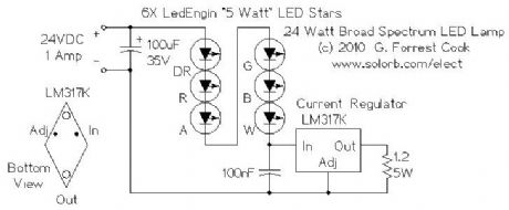
This project involves constructing an energy efficient broad spectrum LED lamp system. The lamp is useful for indoor reflective room lighting. It has a broad color spectrum that more closely approximates the light of the sun when compared to fluorescent bulbs and white-only LEDs. The light level is regulated and the light that is produced does not flicker. The six differently colored LED stars, made by LedEngin, Inc., are rated at 5 watts (nominal). The LED array and associated current regulator consume 1 amp at 24VDC (24 Watts). NEVER stare directly at this lamp when it is running at full operating power, it is DANGEROUSLY BRIGHT.
With the LEDs shown, the combined color of the lamp has a pinkish white hue. The 5 Watt ratings of the LEDs are not precise, the white, blue and green LEDs consume about 4W and the lower voltage red, orange and deep red LEDs consume about 3W. The current regulator keeps the LED brightness constant and insures that the LED series string never draws more than 1 amp of current.
(View)
View full Circuit Diagram | Comments | Reading(1120)
Regulated Dual 3 Watt White LED Lamp
Published:2013/3/7 2:56:00 Author:Ecco | Keyword: Regulated, Dual, 3 Watt, White LED Lamp

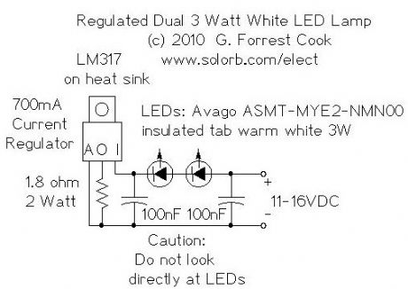

This project involves constructing an energy efficient dual 3 Watt white LED array that runs on 12VDC at 700mA. The lamp is useful for indoor indirect room lighting. The light that is produced does not flicker and has a regulated brightness from 11V to the maximum operating voltage. The Avago 3W white LEDs are rated at 3 watts (nominal). Never stare directly at this lamp when it is running at full operating power, it is dangerously bright.
(View)
View full Circuit Diagram | Comments | Reading(1544)
18 LED dimmable LED lamp
Published:2013/3/7 2:55:00 Author:Ecco | Keyword: 18 LED, dimmable LED lamp
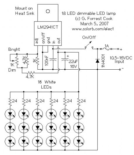
This circuit is a dimmable white LED lamp array with 18 LEDs. The lamp brightness is regulated as long as the input voltage is above 10.5V. A low-dropout analog voltage regulator is used for a simple and relatively efficient design. The lamp produces enough light to use as a a reading lamp or a small work lamp.
(View)
View full Circuit Diagram | Comments | Reading(1826)
High Efficiency 12V White LED Driver
Published:2013/3/7 2:54:00 Author:Ecco | Keyword: High Efficiency , 12V, White LED Driver
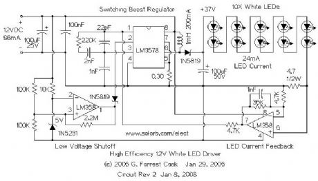

DC powered LED lighting circuits can vary from trivial single LED/series resistor combos to simple analog current regulators to more complicated switching power supply circuits such as this project. There is a tradeoff between simplicity and circuit capabilities. This more complex circuit adds features such as regulated light level across a wide range of input voltages and automatic circuit shutoff on low input voltage. By using a high frequency switching regulator, the power loss associated with the current dropping resistors found in simpler circuits is reduced. This offsets the power consumed by the circuit's active parts. This circuit can power 10 white LEDs at 24mA of current with only 98mA of input supply current when running on 12V. LED intensity is fully regulated across the entire operating voltage range.
This circuit was inspired by F. Garcia's IR LED video illumination circuit, published in the July 2001 edition of Nuts and Volts magazine. I modified the LED count and feedback circuit, and added the important low voltage shutdown feature.
(View)
View full Circuit Diagram | Comments | Reading(4384)
Seven Component Regulated LED Lamp
Published:2013/3/7 2:53:00 Author:Ecco | Keyword: Seven Component, Regulated LED Lamp

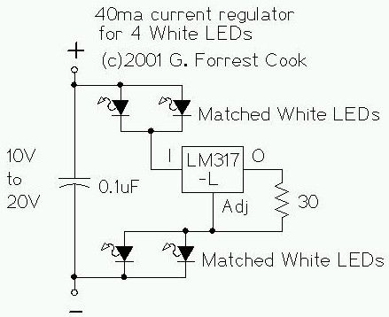
The LM317L and resistor act as a current regulator set to 40ma. Current flows from the battery through one pair of LEDs, through the regulator, through the other pair of LEDs, and back to the battery. The capacitor filters out noise on the power supply lines. The LED pairs must be matched so that the current through them is roughly equivalent. Small resistors could be placed in series with each of the four LEDs to improve the balance, but the parts count would go way up.
(View)
View full Circuit Diagram | Comments | Reading(1032)
Regulated Dual White LED Lamp
Published:2013/3/7 2:52:00 Author:Ecco | Keyword: Regulated , Dual , White LED Lamp
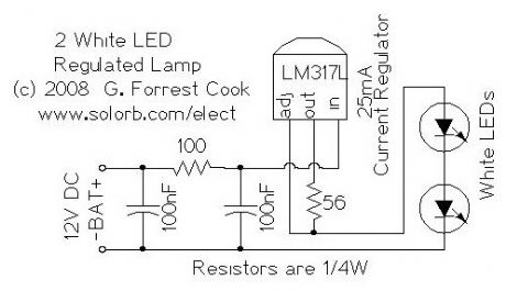

This is an ultra-simple LED spot lamp that uses two white LEDs and a current regulator circuit. It is designed for use in 12V solar powered and automotive/boating applications, but can be used in many other applications. Only seven components are used in this circuit. It produces regulated light output across the 11V to 20V voltage range. The circuit board is potted in silicone to make the lamp completely waterproof.
(View)
View full Circuit Diagram | Comments | Reading(1082)
Low Power LED Voltmeter
Published:2013/3/6 3:23:00 Author:Ecco | Keyword: Low Power, LED Voltmeter

This is a low power voltmeter circuit that can be used with alternative energy systems that run on 12 and 24 volt batteries. The voltmeter is an expanded scale type that indicates small voltage steps over the 10 to 16 volt range for 12 volt batteries and over the 22 to 32 volt range for 24 volt batteries. Power consumption can be as low as 14mw when operated from 12V and 160mw when operated from 24V. This design has been combined with This meter design has been updated and is now part of the 12 Volt Battery Voltage Monitor(BVM1) project, kits are available.
It is possible to set the meter to read equal steps across a variety of upper and lower voltages. The meter saves power by operating in a low duty-cycle blinking mode where the LED indicators are only on and consuming power briefly during a repeating 2 second cycle. The circuit may be switched to a high power mode where the active LED stays on at all times.
Different colored LEDs may be used for the voltage level indicators, this allows the battery state to be read in the dark. With the new blue LEDs, it is possible to have a nice looking rainbow of colors using two each of red, amber, yellow, green, and blue LEDs. The circuit will also work with inexpensive and common red LEDs. If the circuit is to be used in sunlight, ultra-bright LEDs should be used, although even those may be hard to read without some kind of sun shield.
Typical uses include the monitoring of portable battery operated systems and indoor wall mounted home power system charge indicators. The cost of the parts for the circuit is around $25.00 (US) and the parts are commonly available, except for the optional blue LEDs. If blue LEDS are used, expect to pay a premium for them, they cost several dollars each, compared to around 15 cents for the other colors. The blue LEDs do look nice in any case.
(View)
View full Circuit Diagram | Comments | Reading(2312)
4 WAY TRAFFIC LIGHTS Circuit
Published:2013/3/5 20:58:00 Author:Ecco | Keyword: 4 WAY, TRAFFIC LIGHTS

This circuit produces traffic lights for a 4-way intersection. The seemingly complex wiring to illuminate the lights is shown to be very simple, in this diagram.
(View)
View full Circuit Diagram | Comments | Reading(7059)
LED- parallel digital tube LED static display circuit (common anode)
Published:2013/3/5 0:43:00 Author:Ecco | Keyword: LED, parallel digital tube, static display , common anode
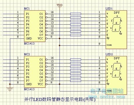
LED- parallel digital tube LED static display circuit (common anode) is shown as figure.
(View)
View full Circuit Diagram | Comments | Reading(1186)
LED - serial LED digital tube dynamic scanning display circuit ( common anode )
Published:2013/3/5 0:42:00 Author:Ecco | Keyword: LED - serial, LED digital tube, dynamic scanning , display circuit , common anode
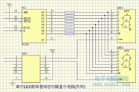
LED - serial LED digital tube dynamic scanning display circuit ( common anode ) is shown as figure.
(View)
View full Circuit Diagram | Comments | Reading(1035)
LED - serial LED digital tube dynamic scanning display circuit ( common cathode )
Published:2013/3/5 0:41:00 Author:Ecco | Keyword: LED - serial, LED digital tube , dynamic scanning , display circuit , common cathode
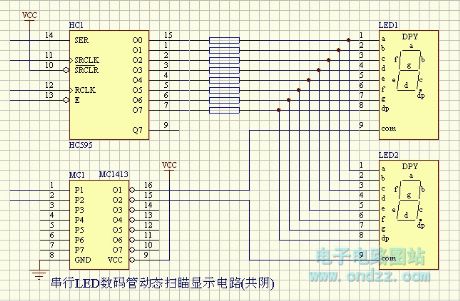
LED - serial LED digital tube dynamic scanning display circuit ( common cathode ) is shown as figure.
(View)
View full Circuit Diagram | Comments | Reading(1093)
POLICE LIGHTS Circuit
Published:2013/3/5 0:33:00 Author:Ecco | Keyword: POLICE LIGHTS
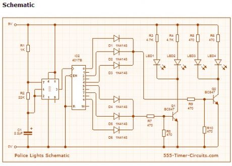
This circuit uses a 555 timer which is setup to both runn in an Astable operating mode. This generates a continuous output via Pin 3 in the form of a square wave. When the timer's output changes to a high state this triggers the a cycle on the 4017 4017 decade counter telling it to output the next sequential output high. The outputs of the 4017 are connected to the LEDs turning them on and off.
(View)
View full Circuit Diagram | Comments | Reading(3278)
MACHINE GUN Circuit
Published:2013/3/5 0:27:00 Author:Ecco | Keyword: MACHINE GUN
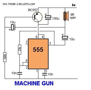
This circuit produces a sound very similar to a machine gun:
(View)
View full Circuit Diagram | Comments | Reading(1326)
LED DIMMER Circuit
Published:2013/3/5 0:25:00 Author:Ecco | Keyword: LED DIMMER
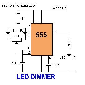
This circuit will adjust the brightness of one or more LEDs from 5% to 95%.
(View)
View full Circuit Diagram | Comments | Reading(1819)
LED DICE (with Slow Down) Circuit
Published:2013/3/5 0:24:00 Author:Ecco | Keyword: LED DICE
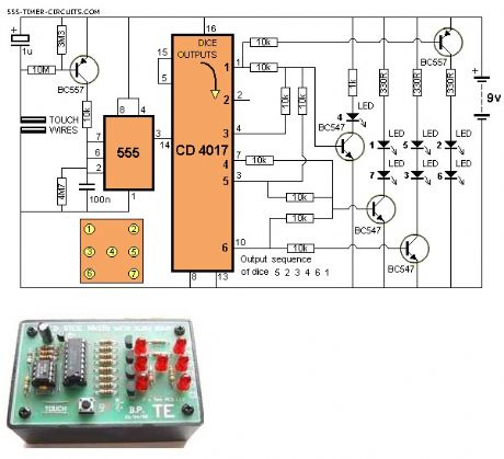
This circuit produces a random number from 1 to 6 on LEDs that are similar to the pips on the side of a dice. When the two TOUCH WIRES are touched with a finger, the LEDs flash very quickly and when the finger is removed, they gradually slow down and come to a stop.
(View)
View full Circuit Diagram | Comments | Reading(2350)
FLASHING RAILROAD LIGHTS Circuit
Published:2013/3/5 0:04:00 Author:Ecco | Keyword: FLASHING RAILROAD LIGHT
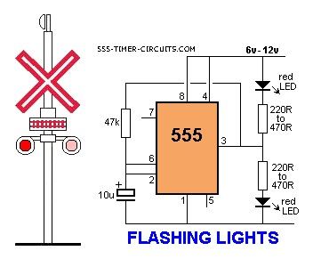
This circuit flashes two red LEDs for a model railway crossing.
(View)
View full Circuit Diagram | Comments | Reading(3685)
Flashing LED Circuit
Published:2013/3/5 0:03:00 Author:Ecco | Keyword: Flashing LED
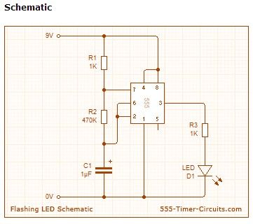
This circuit uses the 555 timer in an Astable operating mode which generates a continuous output via Pin 3 in the form of a square wave. This turns the LED (D1) on and off. The speed at which the LED (D1) is turned on and off is set by the values of R1 and R2.
(View)
View full Circuit Diagram | Comments | Reading(1482)
FLASHING INDICATORS Circuit
Published:2013/3/4 21:49:00 Author:Ecco | Keyword: FLASHING INDICATORS
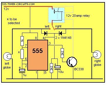
Need to flash turn indicators using a 555 and a single 20 amp relay. Here is our suggestion. The timing resistor needs to be selected for the appropriate flash-rate.
(View)
View full Circuit Diagram | Comments | Reading(1243)
| Pages:7/72 1234567891011121314151617181920Under 20 |
Circuit Categories
power supply circuit
Amplifier Circuit
Basic Circuit
LED and Light Circuit
Sensor Circuit
Signal Processing
Electrical Equipment Circuit
Control Circuit
Remote Control Circuit
A/D-D/A Converter Circuit
Audio Circuit
Measuring and Test Circuit
Communication Circuit
Computer-Related Circuit
555 Circuit
Automotive Circuit
Repairing Circuit