
LED and Light Circuit
Index 2
Automatic Lawn Light with LDR Circuit
Published:2013/12/4 21:25:00 Author:lynne | Keyword: Automatic Lawn Light with LDR
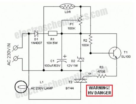
Circuit of a compact and true solid-state automatic lawn light is described here.The circuit can be used to switch on incandescent garden light bulbs at desk and switch off them at dawn. A 10 mm encapsulated light dependent resistor (LDR) here works as the twilight detector.
The whole circuit can be housed in a very small plastic cabinet.For powering the circuit AC 230V household supply is needed. With a little skill and patience, you can easily modify this circuit to drive a number of white LED strings, instead of the incandescent bulb load at the output.
When ambient light is normal, transistor T1 is reverse biased by the low resistance of LDR. Multi-turn palstic trimpot P1 sets the detection sensitivity. If ambient light dims, transistor T1 turns on to drive the triac T2. Now the lamp load at the output of T2 energises.When the ambient light level restores, circuit returns to its idle state and light(s) switched off by the circuit.
Working voltage for the circuit is derived directly from the AC supply input through components D1, R1, D2 and C1. This obviates the requirement of a bulky and noisy step-down transformer.
If you wish to operate the light bulb(s) on a little reduced power,just replace the triac T2 with a suitable silicon controlled rectifier (SCR). This may give a long life to the incandescent load. Finally, the LDR should not be mounted to receive direct sunlight. It may be mounted at the top of the enclosure, pointing to the sky say southwards.
LDR Lawn Lights Circuit Schematic
(View)
View full Circuit Diagram | Comments | Reading(1990)
LDR Flashing LED Circuit
Published:2013/12/3 20:47:00 Author:lynne | Keyword: LDR Flashing LED Circuit
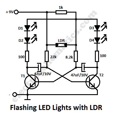
In this flashing led lights circuit, the LDR or photoresistor is connected in such way that when the light intensity varies it will influence the flashing frequency and the brightness of the LEDs. T1, T2 = BC547, BC548, BC549 (any NPN transistor).
You can arrange the LEDs D1 to D4 in cross in order to obtain interesting effecs. The whole flashing led circuit is powered from a 9 volt battery and can be built small enough so it will fit in a matchbox.
Schematic of Flashing Lights with photoresistor
(View)
View full Circuit Diagram | Comments | Reading(2192)
Christmas LED Lights Circuit
Published:2013/12/3 20:44:00 Author:lynne | Keyword: Christmas LED Lights Circuit

Using this simple Christmas LED lights decoration circuit, you can make an 18 LED flasher to decorate the Christmas Tree. The White, Blue and Red LEDs flash at different rates to give a colorful display. It is a light sensitive circuit so that it will turn on in the evening automatically and stays on till morning.
The circuit uses the popular Binary counter IC CD 4060 to flash the LEDs at different rates. Components C1, VR2 and R1 form the oscillator and the output pins 7, 5 and 4 become high / low sequentially. When one output turns high, a set of 3 LEDs turn on and when the same output turns off, the second set turns on. This sequence is similar in the other two sets of LEDs also but with different timings. The speed of the Flashing can be controlled through VR2.
Christmas LED Lights Decoration Circuit Schematic
LDR is provided with VR1 to activate the IC in the evening. In day light, LDR conducts and keep the reset pin 12 of IC1 high to inhibit it from working. When the day light ceases, pin12 becomes low and the flasher starts working. VR1 adjusts the sensitivity of LDR at the required light level. If more LEDs are required, increase the supply voltage to 18 volt DC. The circuit can be powered using a standard 12-18 volt 500 mA adapter.Use High bright transparent LEDs for attractive display. (View)
View full Circuit Diagram | Comments | Reading(2218)
Light Sensor Switch Circuits
Published:2013/11/25 20:04:00 Author:lynne | Keyword: Light Sensor Switch Circuits

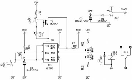
This light sensor switch circuit allows the automatic connection of a lamp when the light is low (at nightfall) and will maintain the lamp ON for a certain period of time.This time can be adjusted with P1 between 1 and 5 hours. The switch is a semiconductor relay S202DS2 and the oscillator is 4060.
Sensor Light Switch Schematic
From the moment that T4 and T5 are opened, relay’s LED start to light and powers the lamp. As soon as one of the transistors is blocked the lamp will go OFF. The phototransistor T3 will be the one that blocks T5 if there is light that falls on T3.
The T2′s base-emitter junction is connected in parallel with T3 and so will be blocked as long there is light. T2 will continuously reset IC1 whose counter outputs will be in “0″ state.
When the night falls R7 provides base current for T2 and the transistor starts to conduct. The counter can now starts to count the impulses from the internal oscillator and in this time the light will bulb will stay lit. After a time, when the output of Q13 goes in state “1″ T4 is blocked. This causes the relay’s LED to go off and the lamp too.
There is no need for external power supply because the light sensor switch is powered directly from the 220V mains. D1 … D5 diodes rectifies the voltage and C4 filters it.C5 is working as a resistor so will need to have the working voltage of minimum 400V but the 630V is preferable. (View)
View full Circuit Diagram | Comments | Reading(1733)
Touch Light Dimmer Circuits
Published:2013/11/25 19:53:00 Author:lynne | Keyword: Touch Light Dimmer Circuits

With IC SLB0586A from Siemens you can build a simple touch light dimmer circuit that will allow you to adjust the lamp intensity. Together with a TIC206D triac, it enables smooth regulation of light intensity from a bulb of 10W – 400W. A coil of 100µH/5A is required to suppress switching noise.
The voltage supply is obtained through R2, C2, D1 and C3 and is about 5.3V below the network potential. The touch sensor that is used to drive the IC is connected at pin 5 through two 4.7MΩ resistors, R5 and R6, in order to ensure user security.
In the adjustable touch lamp schematic we can see three selection connection , for selecting one of three modes of the IC. When the B connection is used, the light will always be ON at the last level that we used. With A or C connection the light will be ON at the minimum intensity. With B or C, the purpose of regulation is reversed with each use.
When the sensor is touched for a short period of time (50 – 400 ms), the lamp will be ON or OFF. If the sensor is touched for a longer period of time it will start the regulation process.
Schematic of the adjustable light with touch sensor
(View)
View full Circuit Diagram | Comments | Reading(1621)
LED as Light Detector
Published:2013/11/24 20:54:00 Author:lynne | Keyword: LED as Light Detector
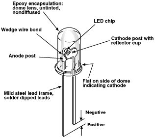
Did you know that the LED can be used as a light detector?In fact green LEDs are the best for this, but all LEDs will detect light and produce a voltage equal to the characteristic voltage-drop. The current they produce is very small, only the super and high bright one can produce a higher output due to the fact that their crystal is more efficient at converting light into electricity.
(View)
View full Circuit Diagram | Comments | Reading(2444)
Flashing Lights Circuits
Published:2013/11/21 20:45:00 Author:lynne | Keyword: Flashing Lights Circuits
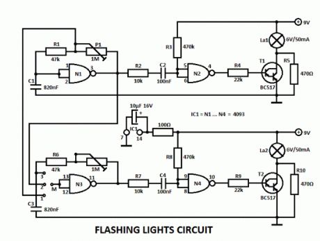
This flashing lights circuit can be used as beacon. The assembly consists basically of two blinking steps that commands two light bulbs. With the help of P1 you can adjust the flashing frequency between some limits.
There are 2 parts for the circuit, the second one works the same way as the other but with the help of a wire bridge or a switch you can choose different operating modes.A bridge between M and 3 means: 2 independent blinks.If there is a bridge between M and 2, then the lamps lights alternatively with a frequency that can be adjusted with P1. And finally there is one more possibility for M and 1, where the lamps blinks at the same time.
The flashing lights circuit works with voltages between 3V and 15V.The lamps voltage must be 2/3 of working voltage. R5 and R10 are chosen so that the lamps are about to light.
Flashing Lamp Lights Circuit Schematic
(View)
View full Circuit Diagram | Comments | Reading(1255)
LED Driver with 555 Timers
Published:2013/11/18 20:32:00 Author:lynne | Keyword: LED Driver
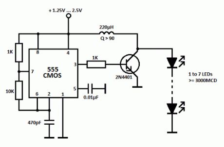
This simple LED driver circuit allows us to drive up to seven LEDs by using a single NiMH (Nickel Metal Hydride) AA cell. The circuit produces voltage pulses at a much higher level than the input supply voltage by pulsing the 220 uH inductor. The inductor must be a high Q (Q>90) power inductor. When the input is 1.25 V and the LEDs are connected, the voltage pulse level will be 23V.The LED driver uses a CMOS 555 timer since it operated with low voltages and can work for about 190 hours when using a single NiMH battery cell rated at 2000 mAh. The 555 timer drives the transistor at 222 kHz rate.
The seven LED groups can be connected paralelly if their forward voltages match. If not, the LED group with the lowest forward voltage value will dim out the other group(s). This parallel connection will not affect the total current drawn from the battery but it will reduce the brightness of the LEDs.
LED Driver Circuit Schematic
When a single 1.25V cell is used, the seven LED group will draw about 8mA from the battery. When the input value increases to 2.5V, the total drawn current will be 20mA. (View)
View full Circuit Diagram | Comments | Reading(2243)
Automatic Street Light Circuits
Published:2013/11/14 19:34:00 Author:lynne | Keyword: Automatic Street Light Circuit

There have been lot of problems in street lights. Major problem in some places is every evening a person has to come and switch ON the street light and it should be again switched off in morning. Yes, this may not be the situation in everywhere but exists in many places.
So this problem can be overcome by using a simple circuit. Below shown circuit will be automatically switched ON and OFF during night and morning times respectively.
Automatic light schematic
In above circuit R1 can be used to adjust the sensitivity. And the working of the circuit is very simple. The LDR will have very low resistance during day time so the transistor Q1 will be in OFF condition. And during night time the resistance will be very high so automatically the transistor Q1 will be ON.
The Q1 is PNP transistor and the emitter of Q1 is given to base of Q2. So the Q2 transistor will be ON only if the transistor Q1 is ON. The TRIAC is used in the circuit to make is circuit complete. As the TRIAC will allow voltage to pass from either directions only when there is a certain threshold voltage in gate terminal. And the gate of TRIAC is controlled by transistor Q2.
So totally the lamp will be ON during night time and will be again switched off during day light. To change the sensitivity of the circuit to light adjust R2.
If you have any doubts, do not hesitate to comment below. We will come to you with an appropriate solution. (View)
View full Circuit Diagram | Comments | Reading(2005)
Single 1.2V NiMH Cell LEDs Flashlight Circuit
Published:2013/11/13 19:14:00 Author:lynne | Keyword: NiMH Cell LEDs Flashlight

The single cell led flashlight circuit is a self-oscillating boost converter. A typical white LED has its best power-efficiency combination at about 20mA, and needs about 3.3V. This makes for a power of about 66mW per LED. In this circuit are 7 series LEDs so we need a driver circuit that will provide about 23V at 20mA, when fed from a 1.2V NiMH rechargeable cell or from a 1.5V alkaline cell.
When switching it on, R1 and D1 bias the transistor into the linear range, through the feedback winding on T1. That causes a current through the 18 turn winding, and thanks to the positive feedback the transistor is driven into saturation. At this moment there will be a base current defined like this: The 1.2V of the cell, plus the 0.2V induced in the feedback winding, minus the 0.7V base-emitter drop of the transistor, make a total of 0.7V, which applied to the 22 ohm resistor gives about 32mA base current. D1 is not conducting a significant current at this time, because the transistor clamps the base voltage to 0.7V and the 3 turn winding subtracts 0.2V from this, so that we end up with only 0.5V across the diode.
This base current keeps the transistor in saturation until its collector current reaches approximately 1A, while the transformer loads up. At this point the transistor will start getting out of saturation, which makes the feedback voltage drop. This very quickly puts the transistor into blockage. The collector voltage will soar as T1 forces current to keep flowing, until D2 starts conducting and discharges the transformer into C2, by means of a quite narrow pulse. During operation this pulse is about 24V high, so that the feedback winding develops -4V, which results in applying about -3.3V to Q1′s base, enough to switch it off very fast, but not enough to make the base reverse-conduct.
As soon as the transformer has fully discharged into C2, the voltage on it breaks down, and the transistor enters conduction to start a new cycle. The oscillating frequency is 30kHz, and the transformer operates at a peak flux density of 0.1 tesla, far away from saturation, and low enough to have very low loss. C2 has to eat the load pulses that start at about 1A, and has to keep the voltage constant enough to feed the LEDs an almost smooth DC. The value given works well. If anyone wants to build this circuit to run 24 hours a day for 30 years, it would be good to pick a capacitor rated for low ESR and a relatively high ripple current, but for flashlight use a plain standard 47µF, 35V electrolytic capacitor works great.
C1 is not strictly necessary. With a good NiMH cell, the circuit works the same without it, so you can save a few cents here. But with the capacitor in place, the circuit keeps working better when the cell is almost fully discharged and its internal resistance gets higher, so it’s better to include it. (View)
View full Circuit Diagram | Comments | Reading(1666)
220V Blinking LED Circuits
Published:2013/11/7 21:02:00 Author:lynne | Keyword: Blinking LED Circuit
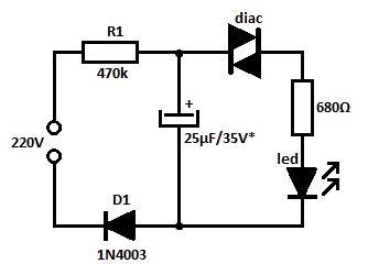
This is a simple blinking led circuit powered from 220V that can be used to mark special places or as voltage indicator. The voltage from the mains charges the capacitor through R1 resistor and D1 diode.As long as the capacitor’s voltage doesn’t exceeds the diac’s switching voltage the cap is acting as a blocked diode. After reaching the switching voltage the diac is conducting and the cap’s discharging current lights up the LED.
The blinking frequency of the LED depends mostly on the RC time constant (in this case T = 11 seconds). The capacitor’s voltage must be a little bit higher than the diac’s breakover voltage.
220 volts blinking LED schematic
With a 1N5758 diac the triggering voltage will be at 20V ± 2. (View)
View full Circuit Diagram | Comments | Reading(2328)
LED DC Voltage Indicator
Published:2013/10/30 21:41:00 Author:lynne | Keyword: LED DC Voltage Indicator

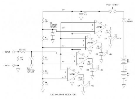
This LED DC voltage indicator circuit is a voltmeter, rather than simply a battery tester. As such it may measure voltages as low as 3V.It utilizes venerable LM741 operational amplifiers applied as comparators that drive LED indicators. Voltage thresholds are 3, 6, 9 and 12V. Above each incremental threshold an additional LED turns on.
DC Voltage Indicator Circuit Schematic
Vcc = 18V
Many voltage indicators rely upon the measurement source voltage for power, but in this voltage indicator case using the LM741, 3V is simply too low for satisfactory operation—the 741 is not specified for low voltage applications. Vcc is higher than what we usually see because it is necessary to have sufficient headroom to bias shunt zener regulator D6. Vcc could have been reduced to 9V by dividing all the threshold reference voltages by a factor of 2, but that would preclude using the LM741 because its input common mode range is specified no lower than 3V from the negative rail—It would definitely not work at 1.5V.
To conserve battery life a “Push to Test” pushbutton switch is used. Another way of doing it would be to use ±9V, and then it could sense voltages down to zero volts if desired. However, this would require the same number of batteries and complicates the pushbutton switch.
Not built or tested
Generally what I submit has been built and tested – this one has not. I have built stuff like this before and used the LM741 as well as the dual version (LM1458), so I have a high degree of confidence that it will work as expected. However, Murphy is always lurking somewhere, just waiting for such an opportunity. The project builder will have the experience of troubleshooting in case it does not function as expected.
Input voltage protection
It is not a good practice to run op amp inputs to the outside world where they would be subject to ESD. R1 and D5 provide the required protection.
D7 protects against accidental reverse battery connection.
Input impedance
Because this dc voltage indicator with LEDs circuit does not derive power from the measurement source, the input impedance is very high. Input impedance is 1M (high but not infinite). In parallel with this is the op amp input bias current that is roughly 4 * 80nA or 320nA. Due to the high impedance, it may be possible to turn on all the LEDs by simply touching the input with your finger. If input noise is an issue, a 0.1uF capacitor across D5 should be helpful.
LED brightness
LED brightness may be varied simply by adjusting the 3.3K series ballast resistor. Most LEDs specify max current to be 20 or 30mA, but efficient green and white versions are blinding at this current so they need much higher value ballast resistors. (View)
View full Circuit Diagram | Comments | Reading(1705)
Light Activated Siren Circuit
Published:2013/10/24 20:10:00 Author:lynne | Keyword: Light Activated Siren Circuit
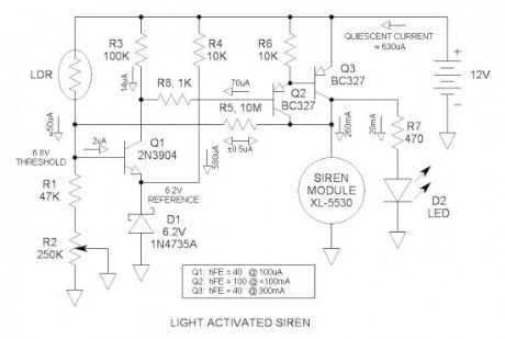
This light activated siren could make an unknowing “victim” wet his pants when turning on the lights in a dark room. This thing is LOUD! Power into the module is 3W and produces a 123db sound level from its 50mm diameter diaphragm. It wavers between 2kHZ and 4kHZ. An LDR senses ambient light level and switches on the power to the siren module via a transistor comparator and a darlington driver.The threshold is adjustable.
Schematic of the light activated siren
Input divider
The LDR and R1 & R2 form a voltage divider whose output voltage is light dependent. As the light level increases, the junction of the LDR and R1 increases. When it reaches 6.8V, Q1 turns on and subsequently triggers the alarm. Pot R2 calibrates the divider for the required light level threshold. The voltage out of the divider may be measured with a voltmeter so you can see what is happening as you debug the circuit.
Transistor comparator
Q1 is an NPN transistor applied as a comparator. Never heard of a transistor comparator before—well now you have—not exactly high performance with limited gain and 600mV offset, but fully functional and perfect for this application. Q1 has a minimum current gain (hFE) of 40 at low current levels. When the LDR is fully off, the Vbe of Q1 is -6.2V. Most transistors are rated for 6 to 7V reverse bias on the base to emitter junction.
Voltage reference
D1 is a 6.2V zener diode that is used as a voltage reference. R4 provides the required bias current. The cathode of the zener is a low impedance node for the emitter of Q1 to work into.
Darlington driver
Q2 & 3 are discrete high current TO-92 PNP transistors wired in the darlington configuration. In this configuration, the hFE is essentially squared so that it provides adequate current gain to easily drive the 280mA load.
Positive feedback
R5 provides about 1% positive feedback to insure positive switching as soon as the threshold is exceeded. This is also called hysteresis. R5 may be adjusted for best performance.
Circuit not tested
Generally the circuits I submit to electroschematics.com have been built and tested. This one has not, but I have a high level of confidence that it will work OK. It simulates fine in my cranial simulator.
Circuit operation
When light falls on the LDR, its resistance decreases and the voltage at the junction of the LDR and R1 increases. When the voltage exceeds 6.8V, Q1 turns on. The collector current of Q1 is the base current of the darlington driver and turns it on. This is called a high-side driver because it works against the positive bus. When voltage appears across the siren module, the voltage across and current through R5 reverses polarity and forces the voltage at the input voltage divider slightly higher thus causing it to “snap” on positively. When three transistors are wired like this, the DC gain is so high that a minute amount of leakage can cause circuit malfunction. R3 and R6 provide paths for leakage current thus insuring reliable operation.
For the future
Temperature activated siren circuit—actually you can do this now by simply replacing the LDR with an NTC thremistor.
Undocumented words and idioms (for our ESL friends)
debug—troubleshooting term. Literally, to get the insects out. From the early days of relay based computers where a moth took down a system when its wings got into the contacts of a relay. (View)
View full Circuit Diagram | Comments | Reading(1210)
Wide Voltage Range LED
Published:2013/9/25 20:08:00 Author:lynne | Keyword: Wide Voltage Range LED

LEDs are well-known for their current consumption, and sometimes a resistor is necessary to limit the current at a moderate value, between 10 to 30 mA.This solution has a drawback, because the value of the resistor must be calculated for each value of voltage.
Replacing the resistor with a FET transistor offers a number of advantages (figure 1). By shorting the gate with source, the transistor forms o current source without requiring additional components. In this case BF256C is used and its constant current is between 11 mA and 15 mA when the voltage is between 5 V to 30 V.
You may use a universal diode like 1N4148 to ensure polarity protection of the LED (figure 2). As a result, the LED can be powered with AC voltages between 5 V and 20 V. At the frequency of 50 Hz the LED is slightly flashing (not quite noticeable) reducing its brightness because of the half-wave rectification.
(View)
View full Circuit Diagram | Comments | Reading(1540)
Voltage Multiplier LED Driver Circuit
Published:2013/9/15 21:42:00 Author:lynne | Keyword: Voltage Multiplier LED Driver Circuit
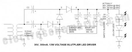
A voltage multiplier is applied as a high source impedance, 36V, 300mA, 12W LED driver. The high source impedance is ideal for driving power LEDs because it accommodates variations in LED junction voltage so that there is minimal change in LED current and brightness. The cascade multiplier is essentially a charge pump that is similar to the popular off-line capacitor limited LED drivers, but offers a substantially higher load current capacity as well as transformer isolation. Note that this circuit topology and application is new to the world.
LEDs are essentially constant voltage devices. Unfortunately, LEDs vary in voltage due to manufacturing variations and temperature. Thus the “constant voltage” is not constant at all—this leads to variations in current when devices are paralleled and also presents a problem when operated from constant voltage power sources—and a serious problem when powered via automotive systems that range from 11 to 14.5V. (View)
View full Circuit Diagram | Comments | Reading(1590)
LED Security Light with PIR Motion Sensor
Published:2013/9/8 20:31:00 Author:lynne | Keyword: LED Security Light with PIR Motion Sensor
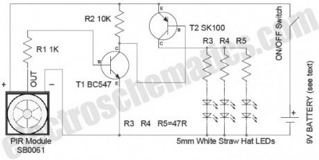
In this security light circuit, High level (3.3V) output from SB0061 is used to switch on six 5mm white straw hat LEDs through a solid-state switch realized using transistors T1 & T2. PIR sensor modules usually have a 3-pin connection: Vcc (+) , Output, and Ground (-) . The pinout may vary, so it is recommend to check the manufacturer’s datasheet to confirm the pins. Besides PIR sensor module also has a 3-pin jumper selection for single or continuous trigger output mode.
The two positions have labels H and L. When the jumper is at H position, the output remains high when the sensor is re-triggered repeatedly. In position L, the output goes high and low every time the sensor is triggered. So a continuous motion will give repeated high/low pulses in this mode.
The PIR LED light security circuit can be powered from a compact 9V rechargeable battery. Note that the battery charger circuit is not included with the circuit schematic. You can use any suitable external 9V battery charger to re-charge the battery pack.
Notes
The PIR sensor requires an initial stabilization time of about 10 to 60 seconds in order to function properly. During this time, the sensor gets familiar with the surrounding environment, and any motion in its field of view should be avoided.
As stated above, the PIR Module needs a “warmup” period of about 10 to 60 seconds, during which time it’s adapting to ambient conditions and may trigger randomly. So anyone using this simple circuit needs to be prepared to accept random triggering for a while after startup.
Due to the high sensitivity of PIR sensor device, it is not recommended to use the module in the following or similar condition:
in rapid environmental changes
in strong shock or vibration
in a place where there are obstructing material (eg. glass) through which IR cannot pass within detection area.
exposed to direct sun light
exposed to direct wind from a heater or air condition
A 9V /250mAh NI-MH Rechargeable battery is used to test the prototype. If possible, try to use a 9V type with higher current capacity.
Value of R3-R4-R5 is optimised for the white LEDs used in the prototype. This needs a “re-touch”, based on the type of white LEDs used in your circuit. (View)
View full Circuit Diagram | Comments | Reading(2180)
LED Solar Lantern Lights
Published:2013/9/2 21:01:00 Author:lynne | Keyword: LED Solar Lantern Lights

Circuit of the LED solar lantern lights presented here is built around one 6V/1W Solar Panel (PhotoVoltaic Panel) and a 4V/800mAh Lead-Acid Battery. Here, commonly available 5mm White Straw Hat LEDs are used as the light source.
DC 6V supply from the solar panel is fed to the rechargeable battery through diode D1 (1N4007) and resistor R1 (15R). Diode D1 functions as a reverse current protector and resistor R1 limits the battery charging current to a safe value. Transistor T1 (BC548) is here wired as an automatic switch to control the LED driver transistor T2 (SL100). T1 disables T2 when the circuit receives sufficient power output from the solar panel.
Switch S1 is an ordinary power on/off switch. Finally, resistor R4 determines the operating current of the white LED (LED 1 – LED 20) assembly. No-load voltage of the solar panel is near 7.2Volt. When connected with the circuit, the PV panel gives around 170mA of current at 6VDC output in middling sunlight, which is more than enough for this circuit. When fully charged, no-load output voltage of the 4V lead-acid battery is near 4.6Volt. According to datasheet, Forward Voltage of the 5mm (actually 4.8mm) White Straw Hat LED (used here) is 3 to 3.2volt, and maximum Continuous Current is about 20mA (Peak Current 30mA).
(View)
View full Circuit Diagram | Comments | Reading(1873)
Adaptive Lighting System for Automobiles
Published:2013/8/26 1:15:00 Author:lynne | Keyword: Adaptive Lighting System for Automobiles
When a vehicle is driven on the highway at night, it is required that light beam should be of high density and should illuminate the road at a distance sufficiently ahead. However, when a vehicle coming in the opposite direction approaches the vehicle with a high-beam headlight, driver of that vehicle will experience a glare, which may blind him. This dazzle effect is one of the major problems faced by a driver in night driving. To avoid this impermanent blindness, a separate filament is usually fitted in the “dual-filament” headlight bulb in a position such that light beam from this second filament is deflected both down and sideways so that the driver of the oncoming car is not blinded. In practice, one mechanical dimmer switch is used by the driver to manually select high (bright) or low (dim) headlight beam. However, this is an awkward task for the driver especially during peak traffics.
Prominent Features:
12V automobile battery powered automatic switching circuit with negligible current consumption in standby mode
Reliable and weatherproof light sensor module (Cds photocell)
Independent variable control to set the “light detection sensitivity to avoid false triggering caused by the influence of other light sources like streetlights
Optional selector switch for “Automatic Signaling Mode” (ASM). In this mode, dim/bright control of headlight is in pulsed, i.e. headlight automatically changes to dim level from bright level and vice versa in a rhythmic style (like a signal to the other motorists) when light from the front coming vehicle is detected by the light sensor module
“Energy Saving Mode” – If the circuit is in active state, by default, headlights automatically goes off when the vehicle enters in a well-lighted area.
(View)
View full Circuit Diagram | Comments | Reading(2178)
Fade LED In and Out with Arduino – Tutorial #2
Published:2013/8/15 21:07:00 Author:lynne | Keyword: Fade LED In and Out with Arduino – Tutorial #2
According to how long it stays in 5V and 0V (using the delay() function) you can obtain the fade effect. If delay() has a low value (for example 50ms or 0.05s) the fading speed will be higher because the Arduino will keep the voltage at pin 11 at a certain value only for 50ms then executes the next for() loop.
When the light intensity reaches the highest point then the second for() loop enters in action. This one will decrease the value of the output voltage on pin 11.
(View)
View full Circuit Diagram | Comments | Reading(1988)
Turn ON an LED with a Button and Arduino – Tutorial #4
Published:2013/8/14 21:11:00 Author:lynne | Keyword: Turn ON an LED with a Button and Arduino , Tutorial #4
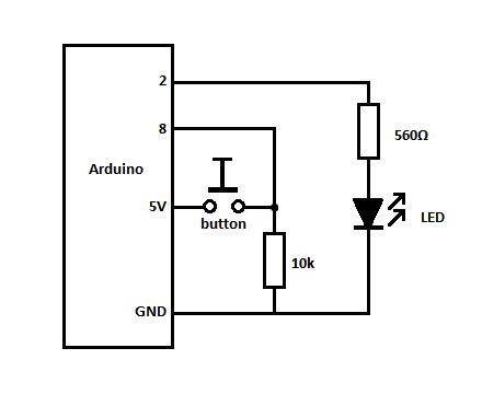
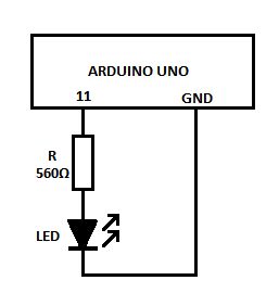
Did you know that you can use Arduino to turn on an LED when you press a button?Well, it is true, you can do this! Leaving the joke aside, let me show how you can achieve this. You will need the Arduino Board, a 560Ω resistor, and LED and the code example below.
(View)
View full Circuit Diagram | Comments | Reading(1255)
| Pages:2/72 1234567891011121314151617181920Under 20 |
Circuit Categories
power supply circuit
Amplifier Circuit
Basic Circuit
LED and Light Circuit
Sensor Circuit
Signal Processing
Electrical Equipment Circuit
Control Circuit
Remote Control Circuit
A/D-D/A Converter Circuit
Audio Circuit
Measuring and Test Circuit
Communication Circuit
Computer-Related Circuit
555 Circuit
Automotive Circuit
Repairing Circuit