
LED and Light Circuit
Index 4
PIC16F84A discolight effect with bass beat control
Published:2013/7/22 20:08:00 Author:muriel | Keyword: PIC16F84A, discolight effect, bass beat control

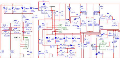
This is an early picture of my discolight effect. Because of the AGC circuit theres no need for potentionmeters for sensitivity adjust. I replaced them with trimmers. Now the microphone is on the control electronics because theres no need to place it outside the box and the possible noises from the surroundings are reduced.You have to choose the distance between Lens-Lamp-Parabola to get sharp beams. Its all about optics.That little ΄wall΄(hindrance) before the Lamp doesnt let the white light to pass through the Lens.I have that box from a friend who had there a bigger home-made parabola. So the box with mine could be smaller but i didnt want to resize it.Its OK.
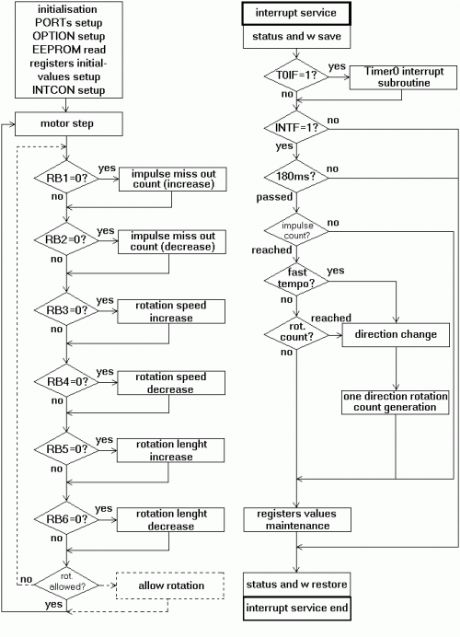
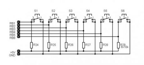
IntroductionShort description of the operation:External circuit converts bass beat of music into pulses.The motor is controlled by them.If theres bass beat recognised then the motor rotates one direction(in full stepping) for a predefined time then stops. If the second beat comes in then it rotates again for the same time and so on.There is a random number generator (from 1 to 4) written into the code which tells how many times have the motor to rotate one direction.After that the PIC changes rotation direction of the motor.If the tempo is too fast (<400msec) then the direction is changed immediately.When the motor stops after the predefined time period a counter is enabled.if beat doesnt come in for 15sec the motor starts to rotate slowly in half stepping.If a beat comes in the counter is disabled and the motor continues its normal rotation in full stepping.Half stepping is smoother but unfortunately the torque is less)The PIC can control the motor after every beat or its possible to bypass some beats.It can be done by pushbuttons. Rotation speed and rotation lenght can be adjusted too.Settings are limited between values to prevent possible register overflow-underflow. These values are saved in EEPROM so after shut-down the settings dont lost.A beat consist of a series of vibrations(dont know the correct english word for that-sorry) so the PIC gets a fewinterrupts.To prevent multi-triggering theres a counter written into the code which disables reaction to beat for200msecs after the first interrupt. 180msec delay is enough if you are using amplifiers output (or line out) as music source. I had to increase it to 200msec because i use microphone and the rooms echo influences operation.
Programming the PIC - AdjustmentsWhen programming the PIC16F84A you need to fill the first three EEPROM locations with the setting values.I used these one: 01 14 E0I programmed the PIC with Ic-Prog using a simple JDM programmer.
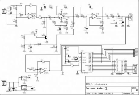
After you succesfully built the whole hardware you need to adjust the trimmers very precisely. If you dont experiment a few times with adjusting them then its possible that the PIC will not recognise every beat because of the small amplifycation level. Or,it will do several things at only one beat.So you have to find the best adjustment.The original circuit which converts bass beat into pulses is from Dan Frasers ΄Audio trigger circuit for light chasers΄(updated by Tomi Engdahl). I only replaced the line-out control with microphone and removed the 555 circuitrybecause of the software solution. The very-own in this project is the software for the PIC microcontroller.
(View)
View full Circuit Diagram | Comments | Reading(1303)
Courtesy Lights
Published:2013/7/22 20:06:00 Author:muriel | Keyword: Courtesy Lights
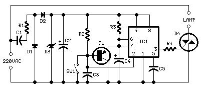
Parts:R1 470R 1/2W ResistorR2 100K 1/4W ResistorR3 1M5 1/4W ResistorR4 1K 1/4W ResistorC1 330nF 400V Polyester CapacitorC2 100µF 25V Electrolytic CapacitorC3,C5 10nF 63V Polyester or Ceramic CapacitorsC4 10µF 25V Electrolytic CapacitorD1,D2 1N4007 1000V 1A DiodesD3 BZX79C10 10V 500mW Zener DiodeD4 TIC206M 600V 4A TRIACQ1 BC557 45V 100mA PNP TransistorIC1 7555 or TS555CN CMos Timer ICSW1 SPST Mains suited Switch
Device purpose:This circuit is intended to let the user turn off a lamp by means of a switch placed far from bed, allowing him enough time to lie down before the lamp really switches off.Obviously, users will be able to find different applications for this circuit in order to suit their needs.
Circuit operation:Due to the low current drawing, the circuit can be supplied from 220Vac mains without a transformer. Supply voltage is reduced to 10Vdc by means of C1 reactance, a two diode rectifier cell D1 & D2 and Zener diode D3. IC1 is a CMos 555 timer wired as a monostable, providing 15 seconds on-time set by R3 & C4. When SW1 is closed, IC1 output (pin 3) is permanently on, driving Triac D4 which in turn feeds the lamp. Opening SW1 operates the monostable and, after 15 seconds, pin 3 of IC1 goes low switching off the lamp.
Notes:The circuit is wired permanently to the mains supply but current drain is negligible.Due to transformerless design there is no heat generation.The delay time can be varied changing R3 and/or C4 values.Taking C4=10µF, R3 increases timing with approx. 100K per second ratio. I.e. R3=1M Time=10 seconds, R3=1M8 Time=18 seconds.Low Gate-current Triacs are recommended.Use a well insulated mains-type switch for SW1. (View)
View full Circuit Diagram | Comments | Reading(990)
Black Lights
Published:2013/7/22 20:05:00 Author:muriel | Keyword: Black Lights
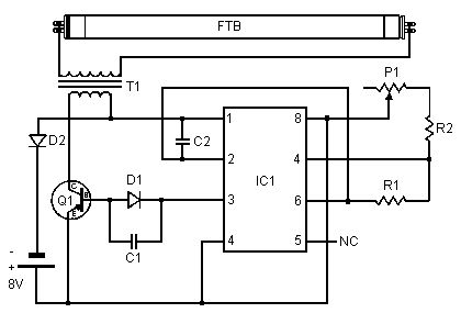
This circuit is a simple ultraviolate light that can be powered by a 6 volt battery or power supply that is capable of supplying 1 or more amps.
PartsC1 0.0047uf Mono CapacitorC2 0.1uf Disc CapacitorD1, D2 1N4007 DiodeFTB Filtered Blacklight TubeIC1 555 Timer ICP1 10k Trim PotQ1 TIP30 PNP Power TransistorR1 470 Ohm ResistorR2 270 Ohm ResistorT1 Medium Yellow Inverter TransformerMISC IC Socket, Heat Sink For Q1, Screw, Nut, Wire and PC Board
Notes:1. P1 changes brightness of the black light tube. (View)
View full Circuit Diagram | Comments | Reading(1384)
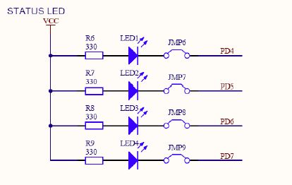
status LED
Published:2013/7/9 3:14:00 Author:muriel | Keyword: status LED
View full Circuit Diagram | Comments | Reading(1227)
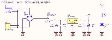
power jack/switch/regulator/power LED
Published:2013/7/9 3:14:00 Author:muriel | Keyword: power jack, switch, regulator, power LED
View full Circuit Diagram | Comments | Reading(1972)
LED4 Schematic
Published:2013/7/5 1:51:00 Author:muriel | Keyword: LED4 Schematic
View full Circuit Diagram | Comments | Reading(1213)
LED3 Schematic
Published:2013/7/5 1:48:00 Author:muriel | Keyword: LED3 Schematic
View full Circuit Diagram | Comments | Reading(1022)
High Current Crossing Flasher Schematic
Published:2013/6/25 21:44:00 Author:muriel | Keyword: High Current, Crossing Flasher Schematic
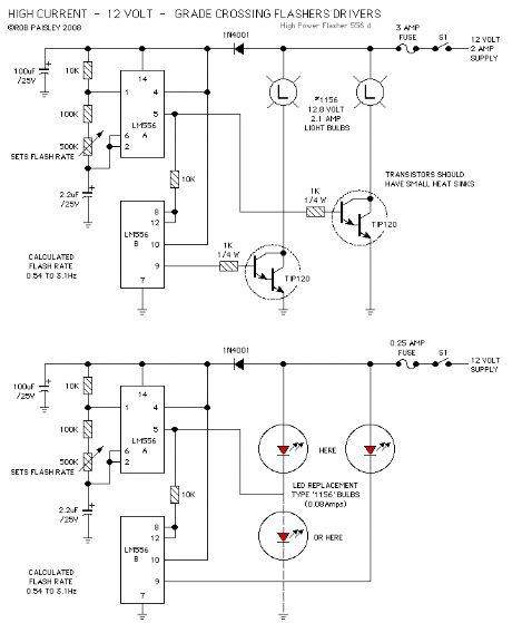
This following circuit shows a simple grade crossing flasher with enough current capacity to drive 12 Volt lamps with 2 Amps current draw. The circuit could be used for open house displays, etc.
The flasher is driven by an LM556 dual time configured in a Push-Pull arrangement.
The flash rate can be adjusted by varying the value of the 500K ohm variable resistor. The flash rate is calculated as being from 0.54 to 3.1 Hertz.
The only real concern with this circuit is the need for a 12 volt power supply large enough for the current required by the lamps. The #1156 automotive lamps specified are rated at 2.1 amps but as only one light is on at a time the current draw for the circuit would be just slightly above 2.1 amps. Other lamps such as the #1141 draw less current. (View)
View full Circuit Diagram | Comments | Reading(1128)
Crossing Light Flasher
Published:2013/6/25 21:43:00 Author:muriel | Keyword: Crossing Light Flasher
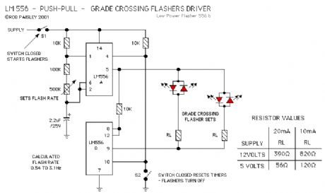
The next circuit uses a dual timer in a Push-Pull output arrangement. While this circuit would be sightly more expensive to build, it would make the wiring of the actual flasher mount simpler as only two connections would be needed.The flashers can be turned on and off by using S1 to control the power to the circuit or by using S2 to RESET the timers. Resetting the timers will make both their outputs go to a LOW state. (View)
View full Circuit Diagram | Comments | Reading(1135)
Low Power Crossing Light Flashers
Published:2013/6/25 21:42:00 Author:muriel | Keyword: Low Power, Crossing Light Flashers
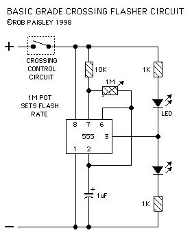
The first circuit is a basic version that can be used in many situations. (View)
View full Circuit Diagram | Comments | Reading(1103)
basic laser pointer circuit
Published:2013/6/21 3:10:00 Author:muriel | Keyword: basic laser pointer circuit
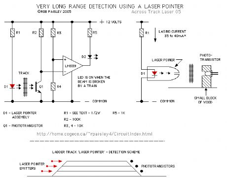
The following diagram shows the basic laser pointer circuit. It is identical to the infrared circuit except that the infrared LED's have been replaced by the laser pointer unit.
Due to the long range of these devices this detector method can easily span great distances and could be used to detect trains in a long section of straight track such as in a lader yard or across the throat of a very wide yard. (View)
View full Circuit Diagram | Comments | Reading(1704)
Bi-Colour LED Output Shifting
Published:2013/6/18 3:58:00 Author:muriel | Keyword: Bi-Colour LED, Output Shifting
View full Circuit Diagram | Comments | Reading(1811)
Bi-Colour LED Output Shifting Schematic
Published:2013/6/18 3:57:00 Author:muriel | Keyword: Bi-Colour LED , Output Shifting Schematic
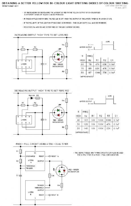
These circuits provide a means of altering the YELLOW output of RED / GREEN type two colour light emitting diodes. These circuits use the LM555 timer chip. (View)
View full Circuit Diagram | Comments | Reading(1259)
LED Blinker Circuit #4
Published:2013/6/18 3:52:00 Author:muriel | Keyword: LED Blinker Circuit
View full Circuit Diagram | Comments | Reading(1196)
LED Blinker Circuit #3
Published:2013/6/18 3:51:00 Author:muriel | Keyword: LED Blinker Circuit

View full Circuit Diagram | Comments | Reading(1299)
LED Blinker Circuit #2
Published:2013/6/18 3:51:00 Author:muriel | Keyword: LED Blinker Circuit

View full Circuit Diagram | Comments | Reading(1034)
LED Blinker Circuit #1
Published:2013/6/18 3:51:00 Author:muriel | Keyword: LED Blinker Circuit
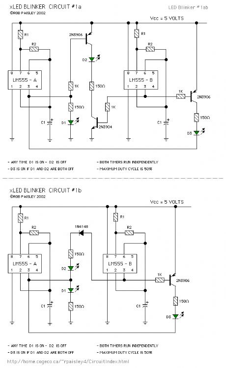
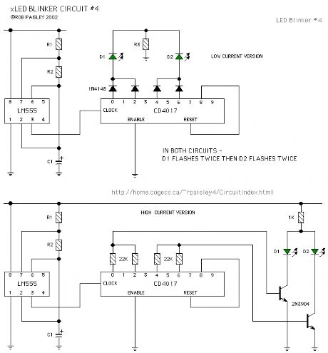
The circuit uses independent timers to flash two light emitting diodes. Any time that light emitting diode D1 is lit__light emitting diode D2 will be switched off. Light emitting diode D3 is on if both D1 and D2 are off.
Two versions of the circuit are shown. The second circuit uses fewer components by taking advantage of the bipolar outputs of the timers.
If the supply voltage is increased a 1N4148 diode should be placed in series with light emitting diode D3. The values of the resistors should also be increased proportionately. (View)
View full Circuit Diagram | Comments | Reading(1164)
Incandescent LED Circuit
Published:2013/6/18 3:44:00 Author:muriel | Keyword: Incandescent LED Circuit
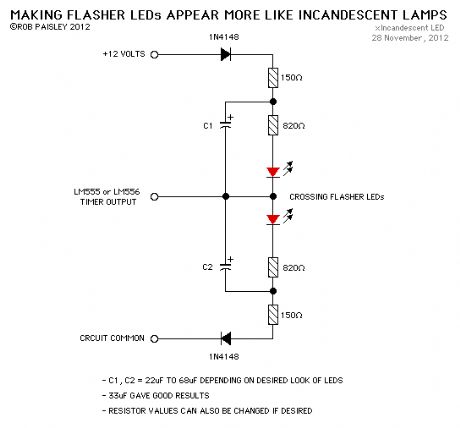
This circuit when used with a 555 timer will cause light emitting diodes to turn on and off more slowly. This will make the LEDs appear similar to incandescent lamps. (View)
View full Circuit Diagram | Comments | Reading(1007)
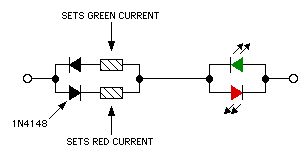
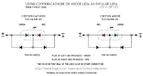
Using Common Cathode Or Anode LEDs As Bipolar LEDs
Published:2013/6/18 3:43:00 Author:muriel | Keyword: Common Cathode , Anode LEDs , Bipolar LEDs
View full Circuit Diagram | Comments | Reading(2087)
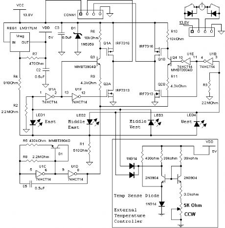
simulate school bus flashers
Published:2013/6/13 21:28:00 Author:muriel | Keyword: simulate school bus flashers
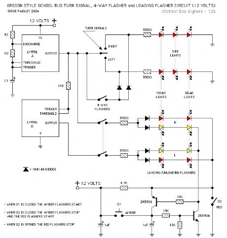
The second circuit was designed to simulate school bus flashers that are to be found in the state of Oregon. The Loading/Unloading lights flash alternately RED or YELLOW depending on whether the bus is slowing down or has stopped and the door is open. (View)
View full Circuit Diagram | Comments | Reading(1479)
| Pages:4/72 1234567891011121314151617181920Under 20 |
Circuit Categories
power supply circuit
Amplifier Circuit
Basic Circuit
LED and Light Circuit
Sensor Circuit
Signal Processing
Electrical Equipment Circuit
Control Circuit
Remote Control Circuit
A/D-D/A Converter Circuit
Audio Circuit
Measuring and Test Circuit
Communication Circuit
Computer-Related Circuit
555 Circuit
Automotive Circuit
Repairing Circuit