
LED and Light Circuit
Index 15
Phase sequence indicator circuit using incandescent and capacitor
Published:2012/11/13 19:55:00 Author:Ecco | Keyword: Phase sequence, indicator , incandescent , capacitor
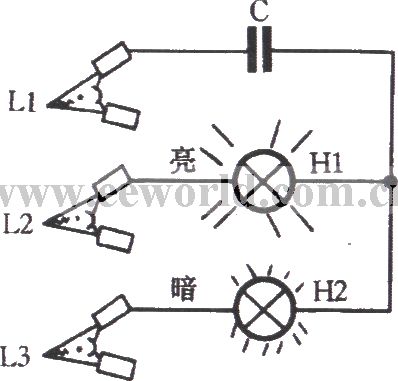
Some devices do not allow the motor reverses, when you install phase sequence identification, the motor wiring is required to be correct. Phase sequence indicator shown in the figure is easy to make, firstly, you can use the insulating handle Alligator Clip to hold a phase of power as the starting phase L1. Another two insulated handle Alligator Clips must touch the other two phases of power supply, then you can identify power supply phase sequence by two bulbs' brightness difference.
(View)
View full Circuit Diagram | Comments | Reading(5271)
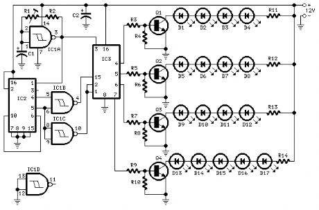
17 LEDs in four groups bar-mode sequence Suitable for shop-windows animation etc.
Published:2012/11/9 0:27:00 Author:muriel | Keyword: 17 LEDs, four groups , bar-mode sequence
View full Circuit Diagram | Comments | Reading(2207)
SIMPLE WHITE LED NIGHT LIGHTS
Published:2012/11/9 0:04:00 Author:muriel | Keyword: SIMPLE WHITE LED NIGHT LIGHTS

This simple circuit is designed to plug into a standard AC electrical outlet. It uses four super bright white light emitting diodes (LED) in conjunction with a capacitor coupled full wave rectifier circuit. The LEDs are mounted in a box and are angled slightly to bounce the light off of a nearby wall. The light should last about 10 years. The circuit draws less than one half of one watt of power and can therefore run continuously. In spite of the low power, the LEDs provide sufficient illumination for most night light applications. Circuit component values for both 120vac and 240vac are shown. (View)
View full Circuit Diagram | Comments | Reading(4514)
3 different Xenon flashing circuits
Published:2012/11/8 0:49:00 Author:muriel | Keyword: 3 different , Xenon , flashing circuits
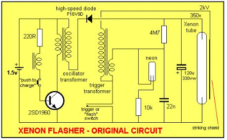
This discussion covers 3 different Xenon flashing circuits from disposable cameras. From them, you will learn circuit tricks that have NEVER been shown in any theory book.The first circuit covers 6 BUILDING BLOCKS.You will need an old disposable Flash Camera plus two extra parts to carry out the modifications. (View)
View full Circuit Diagram | Comments | Reading(3593)
Dual LEDs alternately flasher circuit
Published:2012/11/1 22:34:00 Author:Ecco | Keyword: Dual LEDs , alternately flasher
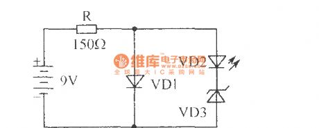
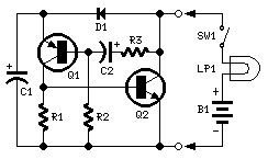
It only uses four elements to constitute an interesting two-tube alternately flasher circuit. VD1 is one flashing light-emitting diode, VD2 uses ordinary light-emitting diode. The working process: VD1 work requires 5V, 30mA. When it gets power, VD1 gets conduction, and there is about 5V voltage adding the series VD2 and VD3, VD3 is the 6.2V zener diode, so VD3 does not work, then only the VD1 is bright; when VD1 is intermittent bright, the supply voltage is added on VD2, VD3 through R current limiting, so VD3 regulator tube works, the current flows through VD2.
(View)
View full Circuit Diagram | Comments | Reading(1682)
0 ~ 5V line graph indicator circuit with LM3914 series of point / line graph LED display driver integrated circuit
Published:2012/10/30 21:09:00 Author:Ecco | Keyword: 0 ~ 5V, line graph, indicator, series , point / line graph , LED display , driver integrated circuit
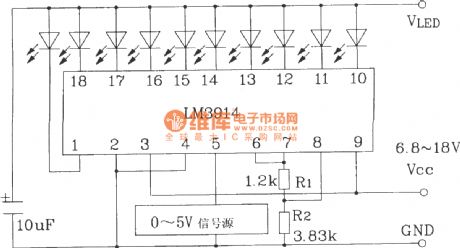
LM3914LED display driver IC is widely used. It uses external components and line changes to form a variety of display and alarm circuits, and cascade may constitute a multi- LED display.
(View)
View full Circuit Diagram | Comments | Reading(3735)
LED dispaly circuit with flashing alarm using LM3914 series of point / line graph LED display driver integrated circuit
Published:2012/10/30 21:11:00 Author:Ecco | Keyword: LED dispaly , flashing alarm , series, point / line graph , LED display , driver integrated circuit
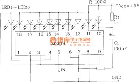
LED dispaly circuit with flashing alarm using LM3914 series of point / line graph LED display driver integrated circuit is shown as the figure.
(View)
View full Circuit Diagram | Comments | Reading(3419)
advertising badge flasher
Published:2012/10/29 21:47:00 Author:muriel | Keyword: advertising badge flasher

View full Circuit Diagram | Comments | Reading(1128)
FLASHING LED ADVERTISING BADGE #2
Published:2012/10/29 21:46:00 Author:muriel | Keyword: FLASHING LED , ADVERTISING BADGE

View full Circuit Diagram | Comments | Reading(1082)
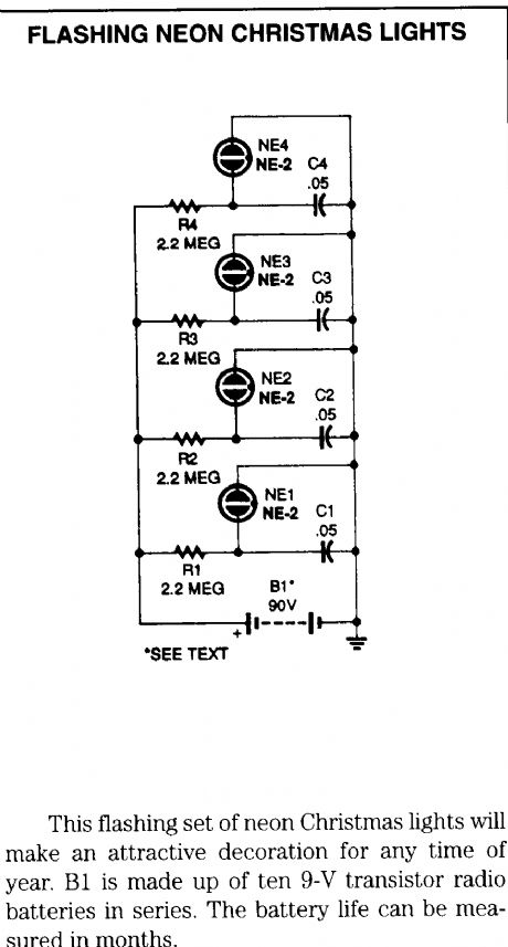
flashing neon charistmas lights
Published:2012/10/29 1:39:00 Author:muriel | Keyword: flashing, neon , charistmas lights
View full Circuit Diagram | Comments | Reading(1558)
8 Random Flashing Leds Circuit
Published:2012/10/29 1:39:00 Author:muriel | Keyword: 8 Random, Flashing Leds Circuit
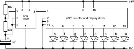
This project flashes eight LEDs in an apparently random manner. It uses a 4060 combined counter and display driver IC which is designed for driving 7-segment LED displays. The sequence is not really random because seven of the LEDs would normally be the display segments, the eighth LED is driven by an output that is normally used for driving further counters. The table below shows the sequence for the LEDs. You can use less than eight LEDs if you wish and the table may help you decide which ones to use for your purpose. (View)
View full Circuit Diagram | Comments | Reading(2750)
6 Channel Auto Reverse Sequential Disco Running Lights
Published:2012/10/29 1:38:00 Author:muriel | Keyword: 6 Channel, Auto Reverse Sequential, Disco Running Lights

View full Circuit Diagram | Comments | Reading(4860)
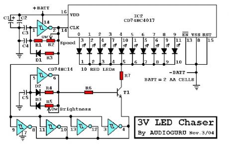
3-V led chaser
Published:2012/10/29 1:37:00 Author:muriel | Keyword: 3-V led chaser
View full Circuit Diagram | Comments | Reading(1896)
pulsing third brake light
Published:2012/10/29 1:36:00 Author:muriel | Keyword: pulsing , third brake light

View full Circuit Diagram | Comments | Reading(1692)
Rotating & Flashing 230V Lights
Published:2012/10/29 1:30:00 Author:muriel | Keyword: Rotating & Flashing, 230V, Lights
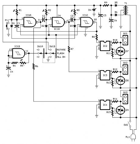
This design can be of some interest for those wanting striking light signs, as it can drive up to three 230V lamp strings in three operating modes.The 15V dc supply is obtained from a nominal 230/24V center tapped ac transformer (T1) and a full wave rectifier (D5 & D6): Zener diode D4 was added to clamp the dc voltage to 15V maximum.Triacs D7, D8 and D9 are insulated from the control circuitry by means of Optoisolators IC2, IC3 and IC4. IC1A, B and C are wired as monostables and cascaded in order to obtain a rotating sequence when the Mode switch SW1 is set in the Rotate position.IC1D acts as an astable multivibrator and generates an adjustable flashlight, driving all three lamp strings at the same time when the Mode switch SW1 is set in the Flash position.The All On operating mode allows all lamps to be on at the same time and can be used either for general illumination or to single out a blown bulb.Each channel can drive several 230V lamps wired in parallel for each string, provided the maximum current of the Triacs is not exceeded. For example, each channel will be able to drive up to 20 40W bulbs.The circuit is also well suited for many small bulbs wired in series like the usual Christmas tree lamp strings decorations. As these are very low power devices, a lot of them can be driven by this circuit. The more lamps per string are used, the more satisfactory will be the resulting effect. (View)
View full Circuit Diagram | Comments | Reading(1482)
220 Volts Flashing Lamps
Published:2012/10/29 1:30:00 Author:muriel | Keyword: 220 Volts , Flashing Lamps
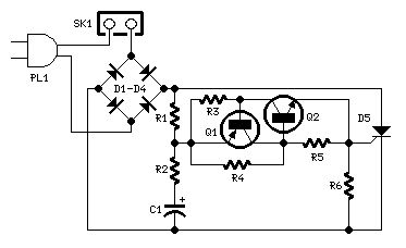
This circuit is intended as a reliable replacement to thermally-activated switches used for Christmas tree lamp-flashing. The device formed by Q1, Q2 and related resistors triggers the SCR. Timing is provided by R1,R2 & C1. To change flashing frequency don't modify R1 and R2 values: set C1 value from 100 to 2200µF instead.Best performances are obtained with C1=470 or 1000µF and R4=12K or 10K. Due to low consumption of normal 10 or 20 lamp series-loops intended for Christmas trees (60mA @ 220V typical for a 20 lamp series-loop), very small and cheap SCR devices can be used, e.g. C106D1 (400V 3.2A) or TICP106D (400V 2A), this last and the suggested P0102D devices having TO92 case. (View)
View full Circuit Diagram | Comments | Reading(1801)
200W Lamp Flasher
Published:2012/10/29 1:29:00 Author:muriel | Keyword: 200W, Lamp Flasher
View full Circuit Diagram | Comments | Reading(1878)
Two-wire Lamp Flasher
Published:2012/10/29 1:29:00 Author:muriel | Keyword: Two-wire , Lamp Flasher
View full Circuit Diagram | Comments | Reading(1340)
2 Transistor LED Flasher
Published:2012/10/29 1:28:00 Author:muriel | Keyword: 2 Transistor , LED Flasher
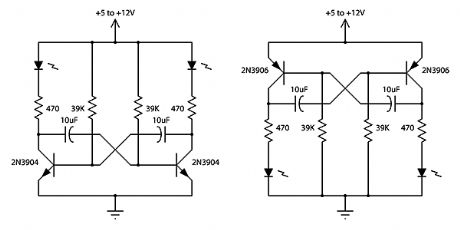
This is a classic 2 transistor astable multivibrator. Many other NPN small signal or switching transistors can be used, including 2N4401, PN2222 or 2N2222 using the circuit on the left. The circuit can also be inverted using PNP transistors such as 2N3906, 2N4403, PN2907, or 2N2907 as shown to the right. The 470 ohm resistors determine the LED brightness. Lower resistance means higher current, and more light. LEDs that require more current or have a higher operating voltage (such as green and yellow) may work better with 300 ohms. The RC time constant of the 39K ohms resistor and the 10uF capacitor determines the on time for each side. (The two sides do not need to match - vary the RC time constant for one side to get a lower or a higher duty cycle). With the values shown, the flash rate is about 1 cycle per second at 50% duty cycle.
(View)
View full Circuit Diagram | Comments | Reading(3304)
2 Transistor 2 LED Flasher
Published:2012/10/29 1:27:00 Author:muriel | Keyword: 2 Transistor , 2 LED Flasher
View full Circuit Diagram | Comments | Reading(2649)
| Pages:15/72 1234567891011121314151617181920Under 20 |
Circuit Categories
power supply circuit
Amplifier Circuit
Basic Circuit
LED and Light Circuit
Sensor Circuit
Signal Processing
Electrical Equipment Circuit
Control Circuit
Remote Control Circuit
A/D-D/A Converter Circuit
Audio Circuit
Measuring and Test Circuit
Communication Circuit
Computer-Related Circuit
555 Circuit
Automotive Circuit
Repairing Circuit