
Index 263
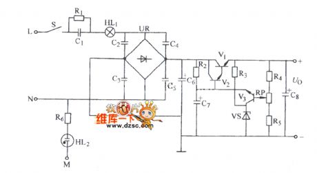
Cap lamp alarm circuit
Published:2011/4/8 2:52:00 Author:Nicole | Keyword: cap lamp, alarm
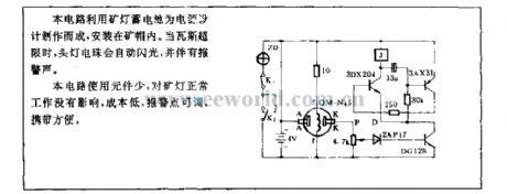
This circuit is designed by using cap lamp battery as power supply, it is fixed in mining cap. When the gas is overflow, then the headlight bulb will flash automatically, and with an alarm.
With less component, the circuit makes no difference to cap lamp normal operation, it also has the advantages of low costs, adjustable alarm point, and convenient to carry. (View)
View full Circuit Diagram | Comments | Reading(747)
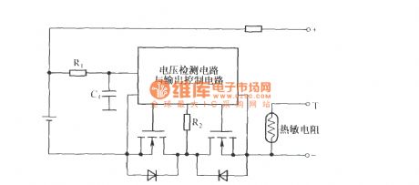
The internal protection circuit of Li-ion batteries
Published:2011/4/8 2:53:00 Author:Nicole | Keyword: Li-ion batteries
View full Circuit Diagram | Comments | Reading(1923)
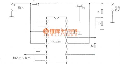
The basic circuit of double level floating charge charger composed of UC3906
Published:2011/4/8 2:53:00 Author:Nicole | Keyword: double level, floating charge, charger
View full Circuit Diagram | Comments | Reading(1357)
Typical application circuit composed of MAX1894/MAX1924 with precharge function
Published:2011/4/8 2:54:00 Author:Nicole | Keyword: precharge function
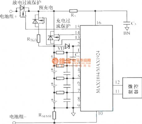
Composed of MAX1894/MAX1924, lithium ion battery protection circuit has two charging control circuits, they are fast charging circuit and precharging circuit. Having precharge function typical application circuit composed of MAX1894/MAX1924 are as below.
(View)
View full Circuit Diagram | Comments | Reading(1070)
The eletric fan circuit decorated by LED
Published:2011/4/8 2:58:00 Author:Nicole | Keyword: LED, electric fan

Used LED to decorate electric fan, it is dazzlingly beautiful and idiosyncratic. After connecting to power supply, the light crosses as arc and it is colorful. The figure (a) is 220V mains supply, the work current is 10mA; the figure (b) is flash circuit, the power supply is from motor tap directly. (View)
View full Circuit Diagram | Comments | Reading(1191)
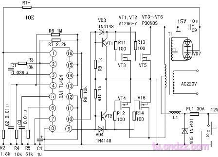
The inversion power supply circuit with automatic voltage regulation function
Published:2011/4/8 2:58:00 Author:Nicole | Keyword: steady voltage, inverting power
View full Circuit Diagram | Comments | Reading(762)
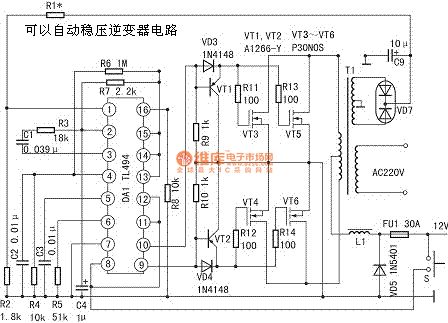
Automatic voltage regulation inverter circuit
Published:2011/4/8 2:59:00 Author:Nicole | Keyword: steady voltage, inverter
View full Circuit Diagram | Comments | Reading(990)
Charging circuit composed of LTC4064
Published:2011/4/8 3:03:00 Author:Nicole | Keyword: charging
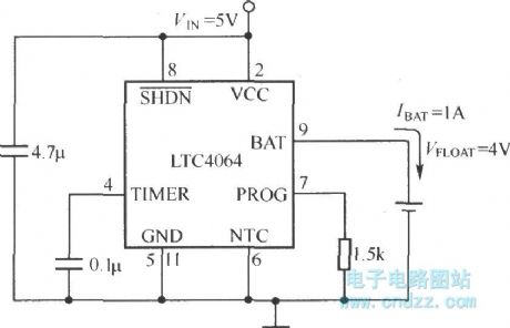
LTC4064 is produced by Linear Technology company, as an independent charger, it is designed for prolonging the service life of lithium ion battery, charging lithium ion batterieswith 4.0 V float voltage(neither is 4.1V nor is 4.2V). LTC4064 slows down the degradation behavior of lithium ion battery and prevent capacitance degradationbecause ofthe low rate of lithium ion battery use(but it should keep full charge state long time). (View)
View full Circuit Diagram | Comments | Reading(592)
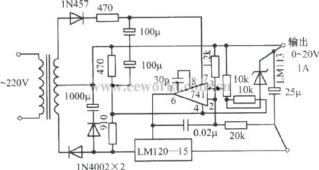
0~20V、1A adjustable regulated power supply composed of LM120-15, Zener diode LM741
Published:2011/4/8 4:38:00 Author:Nicole | Keyword: regulated power supply, Zener diode
View full Circuit Diagram | Comments | Reading(1644)
2V﹑4V﹑6V sub-block output precise stabilized voltage supply circuit
Published:2011/3/31 20:36:00 Author:may | Keyword: sub-block output, stabilized voltage supply

View full Circuit Diagram | Comments | Reading(641)
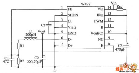
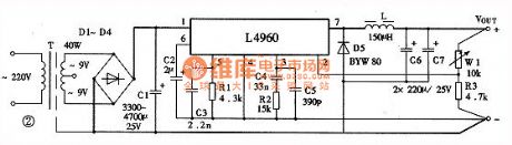
Buck switching regulator circuit diagram composed of W497
Published:2011/3/30 3:17:00 Author:Nicole | Keyword: switching regulator
View full Circuit Diagram | Comments | Reading(783)
2V precise stabilized voltage supply circuit
Published:2011/3/31 20:38:00 Author:may | Keyword: stabilized voltage supply
View full Circuit Diagram | Comments | Reading(591)
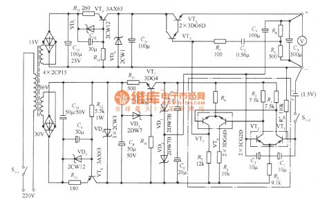
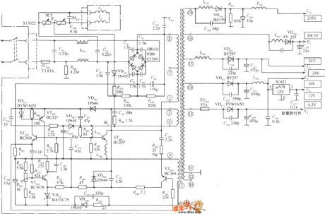
Separately excited switching power supply circuit diagram using self-excited multivibrator as pulse generator
Published:2011/4/1 3:56:00 Author:Nicole | Keyword: switching power supply, self-excited multivibrator, pulse generator
As shown, separately excited switching power supply circuit which used self-excited multivibrator as pulse generator, VTlis the switch tube; VT2, VT3are the push tubes; VT4is the emitter follower. Self-excited multivibrator as the separately excited oscillation circuit is composed of VT5, VT6, C2, C3, R3, R4 and so on. The emitter-coupled differential amplifier is made of VT7, VT8 which as the error amplification. Sampling circuit consists of resistors R7, R8 and R9 potentiometer in series. The reference voltage circuit composed of diode VD4 and R5. Diode VDl, VD2 is used to prevent the push tube VT2, VT3 emitter reversing voltage breakdown. VD3 for the after flow diode; L for the energy storage inductor. The turn-on and cut-off of switching regulator is flipped by the multivibrator, and controlled by emitter follower VT4. The time of multivibrator flip is determined by the error amplifier. The flip time of VT5 from the end to turn is determined by the charge current of VT8 to the C3. VT8 current is larger, the deadline of VT5 is longer. Similarly, The flip time of VT6 from the end to turn is determined by the charge current of VT7 to the C2 VT7 current is larger, the deadline of VL is shorter. When the output voltage down for some reason, VT8 tube collector current of the differential amplifier is decreased, VT7 tube collector current increases, so the conduction time of VT5 is shortened, extended the deadline, leading to the conduction time of VT4 longer, the deadline shorter, and ultimately the conduction time of control switch lengthened, shortened the deadline, so that the output voltage to rise, keep output voltage steady.
(View)
View full Circuit Diagram | Comments | Reading(1773)
Regulator circuit diagram using capacitor as transformer
Published:2011/4/1 3:56:00 Author:Nicole | Keyword: regulator, capacitor, transformer
View full Circuit Diagram | Comments | Reading(646)
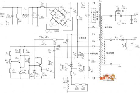
Frequency modulated switching power supply circuit diagram with steady performance
Published:2011/4/1 3:55:00 Author:Nicole | Keyword: frequency modulated, switching power supply
As is shown in the figure, this is another example of switching power supply. The frequency changes are in range of 38 ~ 70kHz, when the input voltage changes are in range of 90 ~ 300V, it can maintain the stability of the output DC voltage.
(View)
View full Circuit Diagram | Comments | Reading(850)
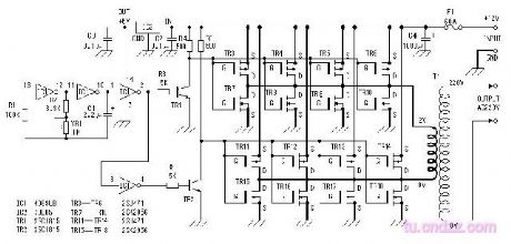
500W inverter
Published:2011/3/31 19:54:00 Author:may | Keyword: inverter
View full Circuit Diagram | Comments | Reading(3618)
Real-time high-voltage switching power supply circuit diagram
Published:2011/4/1 3:54:00 Author:Nicole | Keyword: Real-time, high-voltage, switching power supply
View full Circuit Diagram | Comments | Reading(1731)
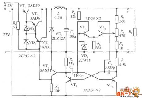
Self-excited feedback transforming switching power supply circuit diagram
Published:2011/4/1 3:54:00 Author:Nicole | Keyword: switching power supply
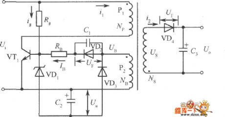
The basic principles of ringing choke-type as shown. When coupled with the input voltage, the current from Rg flowing to the base of switch VTl , so VTl conduction, when the diode of the transformer secondary side reverse biased, without current, so the streaming current of VT1 collector current and Np of transformer windings are equal. Because it is starting from zero, so the base current is not able to make VTl conduction. Rg is called the startup resistor.
(View)
View full Circuit Diagram | Comments | Reading(2488)
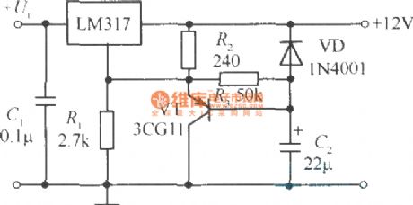
5-12V continuous adjustable power supply circuit
Published:2011/3/31 4:04:00 Author:may | Keyword: continuous adjustable power supply
View full Circuit Diagram | Comments | Reading(663)
Power soft-start circuit adopts capacitor
Published:2011/3/30 3:24:00 Author:may | Keyword: Power soft-start, capacitor
View full Circuit Diagram | Comments | Reading(1352)
| Pages:263/291 At 20261262263264265266267268269270271272273274275276277278279280Under 20 |
Circuit Categories
power supply circuit
Amplifier Circuit
Basic Circuit
LED and Light Circuit
Sensor Circuit
Signal Processing
Electrical Equipment Circuit
Control Circuit
Remote Control Circuit
A/D-D/A Converter Circuit
Audio Circuit
Measuring and Test Circuit
Communication Circuit
Computer-Related Circuit
555 Circuit
Automotive Circuit
Repairing Circuit