
Index 262
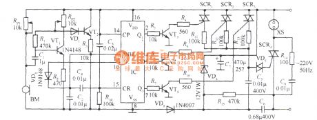
Sound control AC voltage regulator circuit
Published:2011/4/12 3:20:00 Author:Nicole | Keyword: sound control, AC voltage regulator
View full Circuit Diagram | Comments | Reading(783)
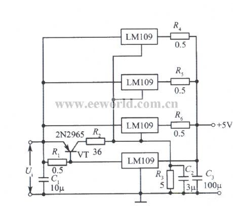
Parallel regulated power supply composed of LM109
Published:2011/4/12 3:35:00 Author:Nicole | Keyword: regulated power supply
View full Circuit Diagram | Comments | Reading(692)
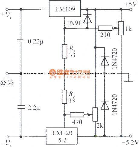
Trimming bistable regulated power supply composed of LM109, LM120
Published:2011/4/12 3:41:00 Author:Nicole | Keyword: regulated power supply
View full Circuit Diagram | Comments | Reading(637)
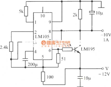
-10V, 1A regulated power supply composed of LM105 integrated regulator, LM195 power transistor
Published:2011/4/12 3:44:00 Author:Nicole | Keyword: regulated power supply, integrated regulator, power transistor
View full Circuit Diagram | Comments | Reading(814)
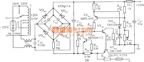
110V regulated power supply
Published:2011/4/12 3:51:00 Author:Nicole | Keyword: regulated power supply
View full Circuit Diagram | Comments | Reading(637)
Micro-power polarity reversal circuit diagram composed of MAX1721
Published:2011/4/2 4:34:00 Author:Nicole | Keyword: Micro-power polarity reversal
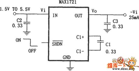
As shown, micro-power polarity reversal composed of miniature (SOT23 package) inverting charge pump IC MAX1721. This circuit just need take a 0.33μF little capacity, small size capacitor on the outside of MAX1721, then the polarity reversal can be completed, that is the output voltage Vo =- Vi.
(View)
View full Circuit Diagram | Comments | Reading(852)
DC voltage bidirectional out-of-limit alarm circuit
Published:2011/4/6 4:10:00 Author:Nicole | Keyword: DC voltage, bidirectional out-of-limit
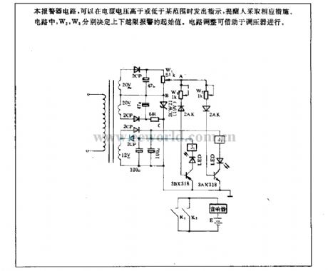
This alarm circuit will issue a directive when the power voltage is higher or lower a range, to remind us to adopt necessary measures. In this circuit, W2, W3 determines the starting value of upper and lower limit alarm. Circuit adjustment can be done by using a regulator.
(View)
View full Circuit Diagram | Comments | Reading(637)
Multi-channel detector circuit
Published:2011/4/12 4:13:00 Author:Nicole | Keyword: detector
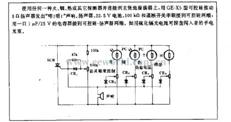
Using any fire, smoke, heat or other detectors and connecting to the primary relaxation oscillator, using GE-X5 thyristor to push 8Ω loudspeaker emits keke . Loudspeaker, 22.5V battery, 100kΩ and on/off switch are in series with the both ends of thyristor; connected a 1μF/25V capacitor to the both ends of thyristor-loudspeaker. Such as using cadmium sulfide photocell can detect the flashlight light beam of interloper. (View)
View full Circuit Diagram | Comments | Reading(1029)
AC electric welding machine no-load energy-saving circuit
Published:2011/4/6 4:11:00 Author:Nicole | Keyword: electric welding machine, energy-saving
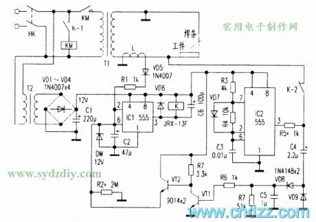
As shown in the figure, T1 is AC electric welding machine transformer. The power switch HK turns on, power transformer T2 obtains the electricity first, filter capacitor C1 obtains about 12V AC voltage. IC1, IC2 is two 555 time base IC. Because the voltage of initial state C2 is 0, the ②、⑥ pins of IC1 is low level, so ③ pin is high level, relay K is not pull-in, AC contactor KM is not work, electric welding machine is no energizing. At the same time, the multivibrator composed of IC2 starts working, the output frequency of ③ pin is about 10kHz pulse singal. After through R5, the later singal is added to one end of T1 secondary, the other end is connected to the grouding of control circuit, duing to T1 secondary winding has large inductance about 10kHz singal, so the current of this loop is lower, the voltage of transformer L is lower too. the other singal is coupled to C4, after VDR、VD9 rectifiers, C5 filter, the DC voltage turns VT1 on, VT2 off. So C2 is without charge current, IC1③ pin keeps high level. The circuit is in no-load energy-saving state.
(View)
View full Circuit Diagram | Comments | Reading(5984)
Laser transmitter linearity control circuit
Published:2011/4/6 4:11:00 Author:Nicole | Keyword: laser transmitter, linearity control
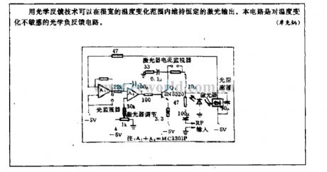
Used optical feedback technique can keep constant laser output in a wide temperature range. This circuit is a optical negative feedback circuit which is insensitive to temperature.
(View)
View full Circuit Diagram | Comments | Reading(730)
Laser diode singal source circuit
Published:2011/4/6 4:11:00 Author:Nicole | Keyword: laser diode, singal source
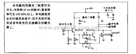
This circuit uses laser diode as switch, can obtain 10ns pulse, the repetition rate is more than 100kHz. This circuit is used in optical fiber communication system, the fiber-optic bundle or single fiber can be coupled to laser.
(View)
View full Circuit Diagram | Comments | Reading(931)
Resistance value choice circuit
Published:2011/4/11 4:15:00 Author:Nicole | Keyword: resistance value, choice
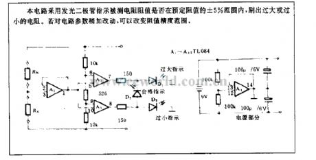
This circuit adopts LED indicates whether the measured resistance value is in the 5% range of reservation precision, removing the too large or too small resistance. If make a few changes to circuit parameter, thenit will change the precision precision range. (View)
View full Circuit Diagram | Comments | Reading(677)
Timing circuit
Published:2011/4/6 4:11:00 Author:Nicole | Keyword: timing
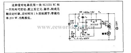
This timing circuit only use a 5GI555 IC and a TRIAC, with other components form non-contact timer. The timing time 1h is continuous regulation, and the loading power is 200W with low power consumption.
(View)
View full Circuit Diagram | Comments | Reading(1464)
Radiation thermometer circuit
Published:2011/4/8 2:46:00 Author:Nicole | Keyword: radiation thermometer
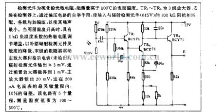
The detecting element is lead sulfide photosensitive resistance, it can measure the surface temperature more than 100℃. TR1~TR3 are 3 stage amplifiers, they are fixed on the detector, through bootstrap function of bias circuit, match input to 300kΩ resistance of radiation detecting element(6ISV). Adding bias voltage to all levels, to minimize the noise. When enviroment temperature rises, the thermistor with 2kΩ NTC adjusts gain, to make up for the reduction of radiation detecting element sensitivity. Final follower drives main amplifier and indication ammeter(no gave). Radiation detecting element outputs 0.3mV, can obtain 1mV through preamplifier, main amplifier outputs 20mV, it has 10% partial difference in the most sensitive range of 200μA ammeter. This circuit has 5 measuring ranges, the range of measuring temperature is 100~500℃. (View)
View full Circuit Diagram | Comments | Reading(613)
The charging system structure chart of distributed valve control seal lead acid storage battery
Published:2011/4/8 2:47:00 Author:Nicole | Keyword: valve control, plumbic acid battery, charging system
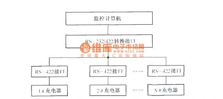
Adopting distributed system is a good way to solve the charging problem of large scale large capacity valve control seal plumbic acid battery, the host is used to monitor overall system, the slave computer is some high power chargers with same structure. (View)
View full Circuit Diagram | Comments | Reading(894)
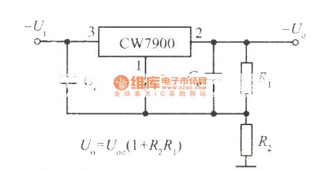
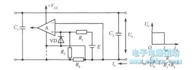
High output voltage integrated regulated power supply circuit 1
Published:2011/4/8 2:48:00 Author:Nicole | Keyword: high output voltage, regulated power supply
View full Circuit Diagram | Comments | Reading(512)
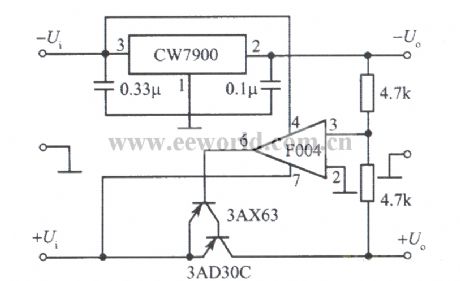
Tracing integrated regulated power supply with positive voltage tracking negative voltage
Published:2011/4/8 2:48:00 Author:Nicole | Keyword: regulated power supply, positive voltage, negative voltage
View full Circuit Diagram | Comments | Reading(672)
Isolating circuit with gain compensation
Published:2011/4/8 2:49:00 Author:Nicole | Keyword: isolating, gain compensation
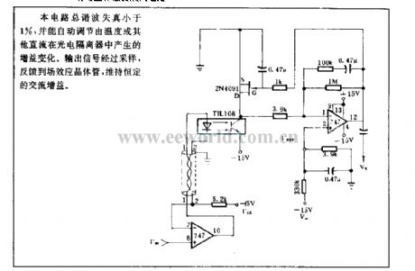
The total harmonics distortion of this circuit is lower than 1%, and it can automatic regulation the gain variations which is produced by temperature or other DC in photoelectric isolator. After sampling, the output singal is fed back to FET, to keep constant AC gain. (View)
View full Circuit Diagram | Comments | Reading(595)
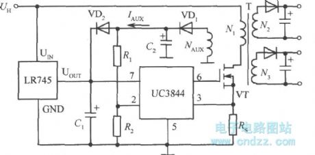
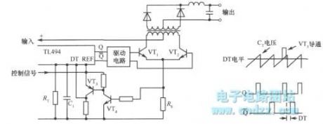
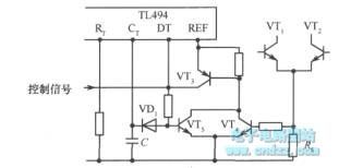
The integrated chip LR745 application case circuit of switching regulated power supply start-up circuit
Published:2011/4/8 2:51:00 Author:Nicole | Keyword: switching power supply, integrated chip
View full Circuit Diagram | Comments | Reading(598)
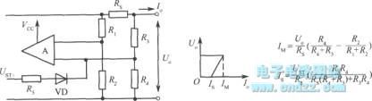
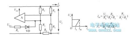
Switching regulated power supply overcurrent protection circuit
Published:2011/4/8 2:52:00 Author:Nicole | Keyword: switching regulated power supply, overcurrent protection
View full Circuit Diagram | Comments | Reading(615)
| Pages:262/291 At 20261262263264265266267268269270271272273274275276277278279280Under 20 |
Circuit Categories
power supply circuit
Amplifier Circuit
Basic Circuit
LED and Light Circuit
Sensor Circuit
Signal Processing
Electrical Equipment Circuit
Control Circuit
Remote Control Circuit
A/D-D/A Converter Circuit
Audio Circuit
Measuring and Test Circuit
Communication Circuit
Computer-Related Circuit
555 Circuit
Automotive Circuit
Repairing Circuit