
Index 267
High accuracy regulated voltage circuit diagram
Published:2011/4/2 3:45:00 Author:Rebekka | Keyword: High accuracy regulated voltage
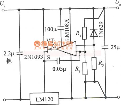
High accuracy regulated voltage circuit diagram is shown as below.
(View)
View full Circuit Diagram | Comments | Reading(623)
Single control regulated voltage circuit diagram 2
Published:2011/4/2 3:46:00 Author:Rebekka | Keyword: Single control regulated voltage

Single control regulated voltage circuit diagram 2 is shown as below.
(View)
View full Circuit Diagram | Comments | Reading(552)
Single control regulated voltage circuit diagram 1
Published:2011/4/2 3:47:00 Author:Rebekka | Keyword: Single control regulated voltage
Single control regulated voltage circuit diagram1 is shown as below.
(View)
View full Circuit Diagram | Comments | Reading(568)
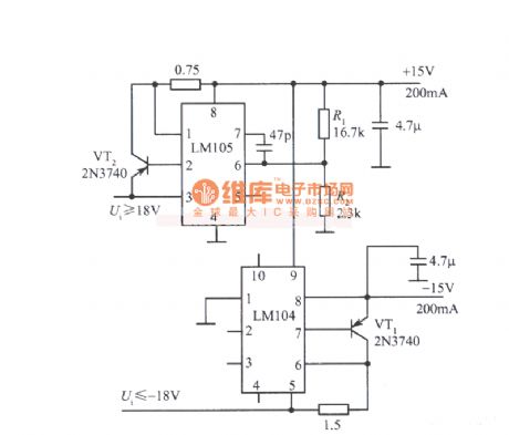
Logic level controled fixed power-supply circuits diagram
Published:2011/4/2 3:48:00 Author:Rebekka | Keyword: Logic level controled, fixed power-supply
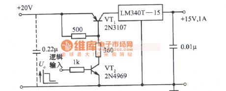
Logic level controled regulators voltage power supply circuit diagram is shown as below.
(View)
View full Circuit Diagram | Comments | Reading(637)
4.5--30V Variable switch regulators voltage circuit diagram
Published:2011/4/1 3:24:00 Author:Rebekka | Keyword: Variable Switch, Regulators Voltage
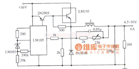
4.5--30V Variable switch regulators voltage circuit diagram is shown as below.
(View)
View full Circuit Diagram | Comments | Reading(670)
Composed of CW1524 buck chopper switching regulator circuit diagram
Published:2011/4/1 3:26:00 Author:Rebekka | Keyword: buck chopper switching regulator
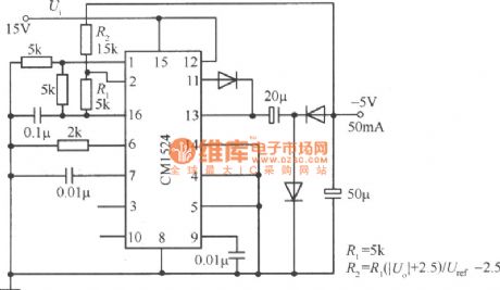
Composed of CW1524 buck chopper switching regulator circuit diagram is shown as below.
(View)
View full Circuit Diagram | Comments | Reading(921)
Composed of CS3842 three outputs DC fixed voltage power supply circuit diagram
Published:2011/4/1 3:26:00 Author:Rebekka | Keyword: three outputs, DC fixed voltage power supply
Composed of CS3842 three outputs DC fixed voltage power supply circuit diagram is shown as below.
(View)
View full Circuit Diagram | Comments | Reading(1404)
Composed of MC33364 8.2V/3A switching DC regulator power supply circuit diagram
Published:2011/4/1 3:27:00 Author:Rebekka | Keyword: switching DC regulator
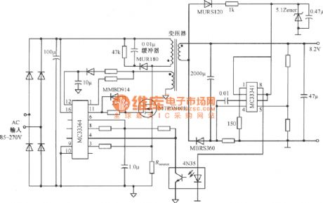
Composed of MC33364 8.2V/3A switching DC regulator power supply circuit diagramis shown as below.
(View)
View full Circuit Diagram | Comments | Reading(1437)
Composed of MC33363 6V/2A isolated switching regulator power supply circuit diagram
Published:2011/4/1 3:29:00 Author:Rebekka | Keyword: isolated switching regulator
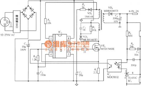
Composed of MC33363 6V/2A isolated switching regulator power supply circuit diagramis shown as below.
(View)
View full Circuit Diagram | Comments | Reading(3696)
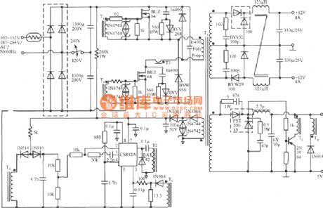
Composed of MC44603P four outputs power supply circuit diagram
Published:2011/4/1 3:30:00 Author:Rebekka | Keyword: four outputs power supply
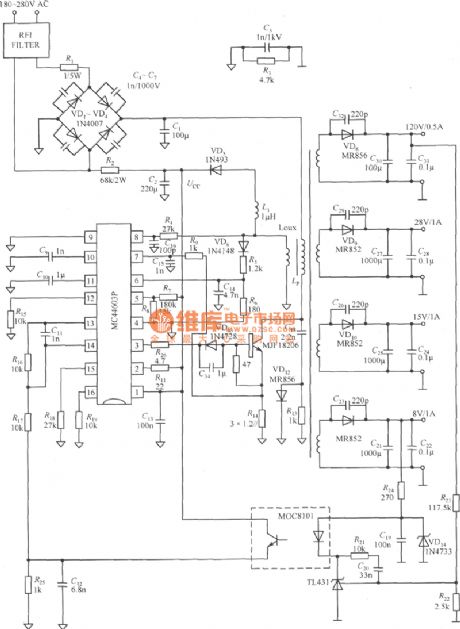
Composed of MC44603P four outputs power supply circuit diagram is shown as below.
(View)
View full Circuit Diagram | Comments | Reading(779)
Composed of CS51227 output 28V/5A DC fixed power supply circuit diagram
Published:2011/4/1 3:31:00 Author:Rebekka | Keyword: fixed power supply
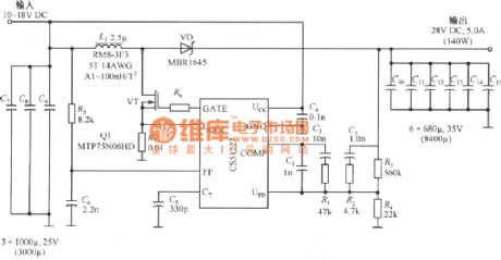
Composed of CS51227 output 28V/5A DC fixed voltage power supply is shown as below. CS51227 is a voltage type PWM Controller, the switching frequency can up to l.0MHz, trigger voltage is 4.7V start current is 75μA. The output voltage of the power supply is 10~18V, output voltage 28V±1%, output current 0~5A, switching frequency 250kHz, output voltage ripple 150mVp-p, 90% efficiency.
(View)
View full Circuit Diagram | Comments | Reading(1229)
Composed of CS3843 and CS5101 output 5V/3.3V switching DC power supply circuit diagram
Published:2011/4/1 3:21:00 Author:Rebekka | Keyword: switching DC , power supply
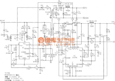
Composed of CS3843 and CS5101 output 5V/3.3V switching DC power supply circuit diagram is shown as below. CS3843 is a fixed frequency PWM controller. The IC is characterized by setting a tone oscillator that used to precisely control duty cycle. There are a reference voltage after temperature compensation, a high-gain error amplifier, current sense comparator and a high current push-pull output that suitable for driving the power tube MOSFET. CS5101 is a bipolar secondary side of the end of class regulator and regulation accuracy can up to 1.0%. Gate drive voltage is 8.0~75V, operating voltage(Ucc) is 8.0~45V, peak output current is 1.5A. There are one 2.0% accuracy, precision voltage reference and an internal compensation error amplifier.
(View)
View full Circuit Diagram | Comments | Reading(1870)
±5--±20V Driven tracking power supply circuit diagram
Published:2011/4/1 3:19:00 Author:Rebekka | Keyword: Driven tracking, power supply
±5--±20V Driven tracking power supply circuit diagram(Driven from the positive side to negative side)circuit diagram is shown as below.
(View)
View full Circuit Diagram | Comments | Reading(677)
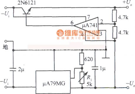
±5--±20V Driven tracking regulator power supply circuit diagram
Published:2011/4/1 3:18:00 Author:Rebekka | Keyword: Driven tracking regulator, power supply
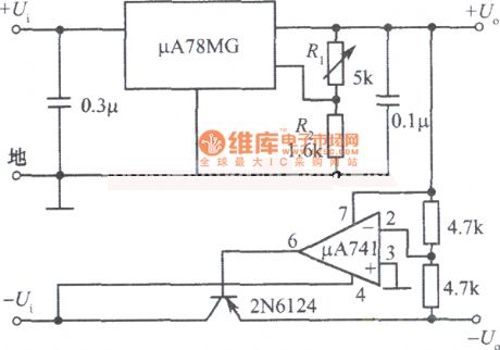
±5--±20V Driven tracking regulator power supply(Driven from the negative side to positive side)circuit diagram is shown as below.
(View)
View full Circuit Diagram | Comments | Reading(585)
LM2622 adopted triple output switch power supply circuit diagram
Published:2011/4/1 3:16:00 Author:Rebekka | Keyword: triple output switch
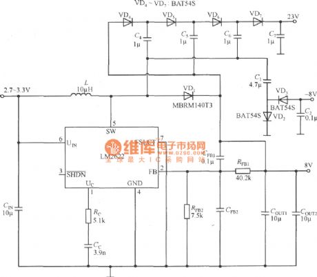
The power circuit diagram of triple output switch posed by the LM2622 is shown as below. LM2622 is a 600kHz step-up PWM DC / DC Converter. It converts 3.3V input voltage to8V, -8V and 23V three output voltages. The output current can up to l.6A. You can use filters and low noise components, the voltage can be as low as 2.0V.
(View)
View full Circuit Diagram | Comments | Reading(1768)
Composed of MAX1822 and MAX333 1~4 channel load switch circuit diagram
Published:2011/4/1 3:14:00 Author:Rebekka | Keyword: 1~4 channel load switch
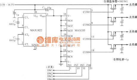
Composed of MAX1822 and MAX333 1~4 channel load switch circuit diagram is shown as below. MAX333 is composed of four amplifiers. When the switch signal SWl ~ SW4 provided to the MAX333 and MAX1822 input signal with the same N01 ~ N04, Comparison of the corresponding output of the amplifier COMl ~ COM4 is high, so the load connected to the corresponding switch.
(View)
View full Circuit Diagram | Comments | Reading(1738)
Composed of MAX1822 and 74C906 1~6 channel load switches circuit diagram
Published:2011/4/1 3:12:00 Author:Rebekka | Keyword: 1~6 channel load switches
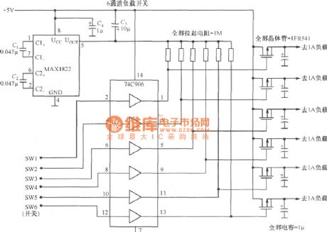
Composed of MAX1822 and 74C906 1~6 channel load switches circuit diagram is shown as below.
MAX1822 is charge pump power supply, its input voltage is in the range of 3.5~16v selection, its output voltage is 11V. You can drive low-impedance N-channel MOSFET. 74C96 is six inverter, SWI~SW6 6 switch signals can be feeded at the same time, alone or in random combinations. This is determinedby requirments for the working condition of load swiches. (View)
View full Circuit Diagram | Comments | Reading(1519)
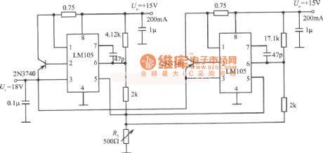
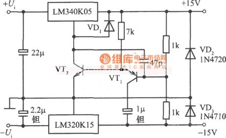
±15V Tracking regulator power supply circuit diagram 5
Published:2011/4/1 3:12:00 Author:Rebekka | Keyword: Tracking Regulator
±15V Tracking regulator power supply circuit diagram 5 is shown as below.
(View)
View full Circuit Diagram | Comments | Reading(702)
±15V Tracking regulator power supply circuit diagram 4
Published:2011/4/1 3:11:00 Author:Rebekka | Keyword: Tracking Regulator
±15V Tracking regulator power supply circuit diagram 4 is shown as below.
(View)
View full Circuit Diagram | Comments | Reading(663)
±15V Tracking regulator power supply circuit diagram 3
Published:2011/4/1 3:05:00 Author:Rebekka | Keyword: ±15V Tracking Regulator
±15V Tracking regulator power supply circuit diagram 3 is shown as below.
(View)
View full Circuit Diagram | Comments | Reading(1252)
| Pages:267/291 At 20261262263264265266267268269270271272273274275276277278279280Under 20 |
Circuit Categories
power supply circuit
Amplifier Circuit
Basic Circuit
LED and Light Circuit
Sensor Circuit
Signal Processing
Electrical Equipment Circuit
Control Circuit
Remote Control Circuit
A/D-D/A Converter Circuit
Audio Circuit
Measuring and Test Circuit
Communication Circuit
Computer-Related Circuit
555 Circuit
Automotive Circuit
Repairing Circuit