
Index 275
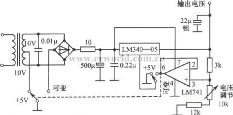
Constant voltage and adjustment regulated power supply composed of LM340-05
Published:2011/4/6 0:54:00 Author:Nicole | Keyword: constant voltage, adjustment, regulated power supply
View full Circuit Diagram | Comments | Reading(828)
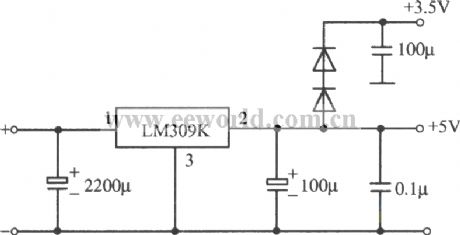
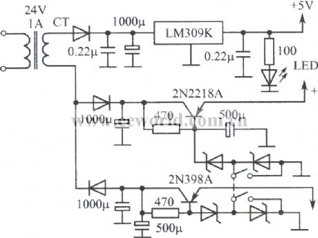
5V、1A regulated power supply circuit composed of LM309K integrated regulator
Published:2011/4/6 0:56:00 Author:Nicole | Keyword: regulated power supply, integrated regulator
View full Circuit Diagram | Comments | Reading(875)
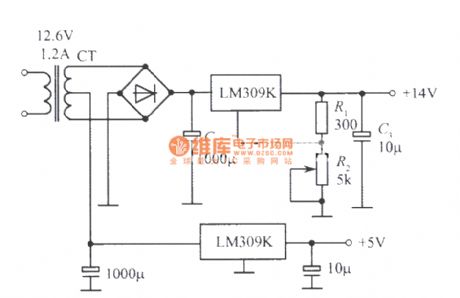
Double regulated power supply composed of LM309K
Published:2011/4/6 1:49:00 Author:Nicole | Keyword: regulated power supply
View full Circuit Diagram | Comments | Reading(2313)
Charging circuit composed of LP3945
Published:2011/4/6 2:22:00 Author:Nicole | Keyword: Charging
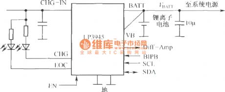
LP3945 can change the working parameter of lithium ion battery, it also can read the state of constant current and constant voltage register through IC interface, then inquiry the state of charging period. (View)
View full Circuit Diagram | Comments | Reading(645)
Multi-channel regulated power supply composed of LM309K
Published:2011/4/6 1:50:00 Author:Nicole | Keyword: regulated power supply
View full Circuit Diagram | Comments | Reading(867)
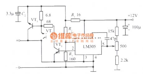
12V、10A regulated power supply composed of LM305
Published:2011/4/6 1:52:00 Author:Nicole | Keyword: regulated power supply
View full Circuit Diagram | Comments | Reading(2591)
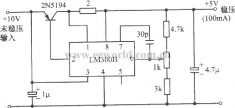
5V regulated power supply composed of LM300H integrated regulator 1
Published:2011/4/6 1:54:00 Author:Nicole | Keyword: 5V regulated power supply, integrated regulator
View full Circuit Diagram | Comments | Reading(832)
LM317 integrated regulator circuit
Published:2011/4/6 2:06:00 Author:Nicole | Keyword: integrated regulator
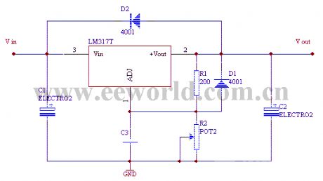
It is usual adjustment integrated regulator, the maximum output current is 2.2A, the output voltage is in the range of 1.25~37V. The connection is above. There is 1.25V voltage reference between 1, 2 pins. In order to ensure the output performance of regulator, R1 should lower than 240Ω. To change the resistance of R2 can adjust the regulator voltage value. D1, D2 is used to proect LM317. (View)
View full Circuit Diagram | Comments | Reading(1654)
Solar light control switch composed of silicon photocell
Published:2011/3/29 21:16:00 Author:Nicole | Keyword: Solar light control switch, silicon photocell
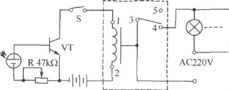
The circuit consists of crystalline silicon solar cell (photovoltaic cell), relay, variable resistor, transistor, 9V DC power supply, manual switches and so on. The main contacts 1, 2 of relay is the coil contacts, 3, 4 connect normally closed contact, 3, 5 connect normally opened contact, the 3, 4, 5 connect to the load circuit. When the light is greater than 220lm, S will be closed, power supply make the transistor forward bias, relay closed, then normally closed contacts 3, 4 of the control load disconnected, normally opened contact 3, 5 closed, street light or lighthouse loop disconnected, and then went out. In rainy days, the light is just below 220lm, and the light is off, it should cut off the switch S, relay releases, then the circuit to restore original state.
The components can be selected: amorphous silicon cell with six conduction units, 37.82cm2, leading to positive and negative. VT selects 3DG6 models. Relay adopts highly sensitive, the operation voltage is 9V, the internal resistance is in the range of 300Ω ~ 2kΩ.
(View)
View full Circuit Diagram | Comments | Reading(2232)
Triggered switch circuit composed of silicon photocell
Published:2011/3/30 1:32:00 Author:Nicole | Keyword: triggered switch, silicon photocell
As shown in the figure, the trigger has two stable states which composed of VT1 and VT2. When one of transistors turns on, the other is closed. As long as changing the light intensity, the output voltage of silicon photocell changed, it can make circuit transit from one state to another, so as to achieve the purpose of light control.
(View)
View full Circuit Diagram | Comments | Reading(645)
Photoelectric tracking circuit composed of silicon photocell
Published:2011/3/30 0:58:00 Author:Nicole | Keyword: Photoelectric tracking circuit, silicon photocell
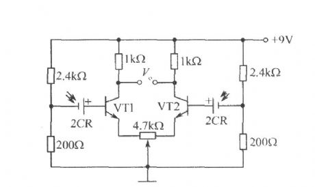
As shown in the figure, using two silicon photovoltaic cells with similar performance as light receiving device, when incident light flux is the same Vo = 0, agency works with predetermined manner. when the optical system has slight deviation, the received luminous flux of two silicon photovoltaic cells will change, then Vo ≠ 0, after amplified, the differential output signal can drive the implementing agencies (such as micro-motor) to orrect the system state, until Vo=0, so as to achieve tracking.
(View)
View full Circuit Diagram | Comments | Reading(2306)
Light control switch circuit composed of silicon photocell
Published:2011/3/29 22:46:00 Author:Nicole | Keyword: Light control switch, silicon photocell
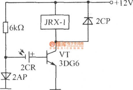
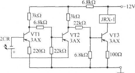
As shown in the figure, in the absence of illumination, VT cuts off (or has smaller collector current, but not enough to relay); After the silicon photocell with light irradiation, it will produce positive voltage to make VT turn on and relay start.
(View)
View full Circuit Diagram | Comments | Reading(1168)
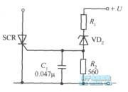
Instance of over-voltage protection circuit
Published:2011/3/30 1:37:00 Author:Nicole | Keyword: over-voltage protection circuit
View full Circuit Diagram | Comments | Reading(489)
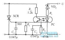
Flash light control device composed of silicon photocell
Published:2011/3/29 22:33:00 Author:Nicole | Keyword: Flash light control device, silicon photocell
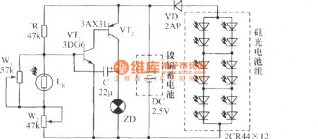
As shown in the figure, divider circuit is made of resistor R, optoelectronics LR, potentiometer W1 and W2. When there is no light at night, the LR resistance is higher, the pressure drop is greater, so the base input current of transistor VT1 is large, VT1 conduction, VT2 is conducted too, the base current is amplified by VT1 and VT2, a part of current is outputed by collector of VT2, and then it is coupled to the base of VT1 through capacitor C to form positive feedback, meet the oscillation condition of circuit. As the large capacity of C, the oscillation frequency is very low, the oscillation signal which has been amplified in the form of impulsive current transport to signal light ZD by VT2, then it winking. When LR is irradiated by light in the day, LR resistance decreased, so the base current from R flow to VT1 is reduced bacause of diversion, VT1 turns into cut-off, the same as VT2, ZD goes out. At this time, duing to light irradiation, the silicon photocell group produce higher voltage, and charge to battery. Ajust R, C can change the flash frequency and light off time ratio. Since W1 is in series with W2 after in parallel with LR, so adjust the resistance of potentiometer W1 and W2, can change the voltage Veb between base and emitter of VT1. General silicon tube turns on when Veb ≥ 0.6V ~ 0.7V; conversely, it cuts off, so you can according to the needs to make the lamp lighted or extinguished.
(View)
View full Circuit Diagram | Comments | Reading(785)
Opto-electrical linear detection circuit
Published:2011/3/30 2:29:00 Author:Nicole | Keyword: linear detection circuit
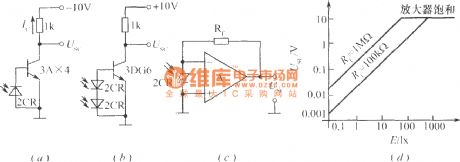
The figures (a), (b) are the light current amplification circuit which work in the linear region. The transistor in figure (a) must be germanium tube. Because the maximum open circuit voltage of photocell is only 0.6V, while the silicone tube turn on need 0.7V. When the output voltage produced by light is more than 0.3V, transistor 3AX4 starts to conduct, output voltage Usc begins to decrease from -10V. Due to the resistance of 3AX4 is lower, so it can obtain good linear output. The figure (b) adopts two photocells in series, transistor uses silicon tube. The circuit in figure (c) is connected with operational amplifier, the equivalent load resistance is zero, so the output voltage of operational amplifier is equal to the product of silicon photocell short-circuit current Isc and amplifier feedback resistor Rf, that is USc = IscRf, and the output has good linearity, as shown in (d).
(View)
View full Circuit Diagram | Comments | Reading(624)
Fixed triple pin regulator output voltage adjustable circuit
Published:2011/3/30 21:23:00 Author:Nicole | Keyword: triple pin regulator, output voltage, adjustable circuit
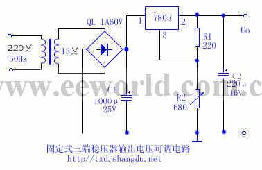
The actual circuit uses fixed three-port integrated manostat circuit 7805 to design and manufacture continuously adjustable DC stabilizer as shown, in figure R1 is 220Ω, R2 is 680Ω mainly used to adjust output voltage. The output voltage is Uo ≈ Uxx (1 + R2/R1), this circuit can achieve output voltage continuously adjustable when the steady voltage is in the range of 5 ~ 12V. The circuit proves: (1)R1 is a fixed resistance, change the resistance of R2 can obtain continuously adjustable output, the approximation of output voltage Uo is Uxx (1 + R2/R1). (2)The maximum output voltage is limited by the maximum input voltage and minimum input-output differentials of regulator, the maximum input voltage of fixed three-port integrated manostat circuit 7805 is 35V, input-output differentials should keep more than 2V, because the DC input voltage of regulator is 14V, so the maximum output voltage is +12V. (3)Results show that within regulator range, the accuracy of regulator is ± 0.03.
(View)
View full Circuit Diagram | Comments | Reading(1153)
Fixed output integrated voltage regulator base circuit
Published:2011/3/30 20:31:00 Author:Nicole | Keyword: fixed output, integrated voltage regulator

View full Circuit Diagram | Comments | Reading(491)
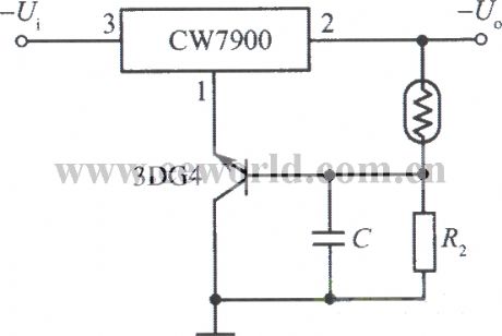
Output voltage decrease with optical control voltage regulator lighting
Published:2011/3/30 21:52:00 Author:Nicole | Keyword: output voltage, optical control voltage regulator
View full Circuit Diagram | Comments | Reading(502)
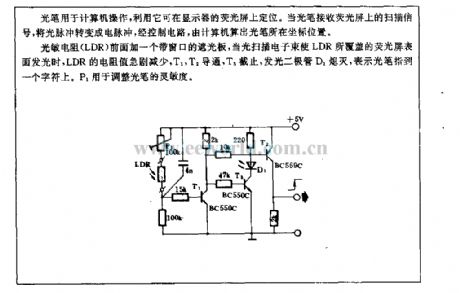
Light pen curcuit
Published:2011/3/30 19:52:00 Author:Nicole | Keyword: light pen
View full Circuit Diagram | Comments | Reading(601)
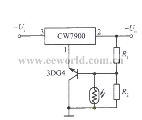
Output voltage rise with optical control voltage regulator lighting
Published:2011/3/30 21:55:00 Author:Nicole | Keyword: output voltage, optical control voltage regulator
View full Circuit Diagram | Comments | Reading(536)
| Pages:275/291 At 20261262263264265266267268269270271272273274275276277278279280Under 20 |
Circuit Categories
power supply circuit
Amplifier Circuit
Basic Circuit
LED and Light Circuit
Sensor Circuit
Signal Processing
Electrical Equipment Circuit
Control Circuit
Remote Control Circuit
A/D-D/A Converter Circuit
Audio Circuit
Measuring and Test Circuit
Communication Circuit
Computer-Related Circuit
555 Circuit
Automotive Circuit
Repairing Circuit