
Amplifier Circuits-Audio
Index 4
Audio splitter amplifier circuit with TL084
Published:2012/9/11 20:26:00 Author:Ecco | Keyword: Audio, splitter , amplifier
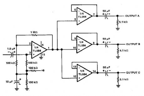
The three-channel amplifier output distribution uses a single TL084. The first step is to capacitive coupling with a p. 1.0 ~ electrolytic capacitor. The entries are railways Vee Y2 or 4.5 V. This allows using a single 9 V power supply A voltage gain of 10 (1 M ohm ohm/l00 k) is obtained in the first stage, and the other three floors are connected as a unity gain voltage followers. Each output stage drives independently via an amplifier output 50 pF capacitor to the resistance of 5.1 k ohm load. (View)
View full Circuit Diagram | Comments | Reading(7950)
Headphone Amplifier circuit
Published:2012/9/11 20:25:00 Author:Ecco | Keyword: Headphone , Amplifier
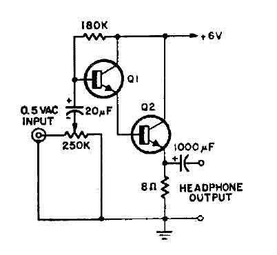
This is a simple headphone amplifier. You can use any NPN transistor. (View)
View full Circuit Diagram | Comments | Reading(4080)
Current limiting audio amplifier circuit
Published:2012/9/11 1:38:00 Author:Ecco | Keyword: Current limiting , audio amplifier
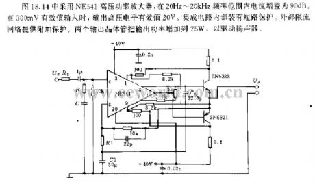
The circuit shown in Figure 18.44 uses NE541 high voltage power amplifier, and its current gain is 90dB at the frequency range of 20Hz ~ 20kHz; when it has 300mV rms input, output high voltage level RMS is 20V. The internal IC is equipped with short-circuit protection. The external current limiting network provides the additional protection. The two output transistors can increase the output power to 75W to drive the speaker.
(View)
View full Circuit Diagram | Comments | Reading(1749)
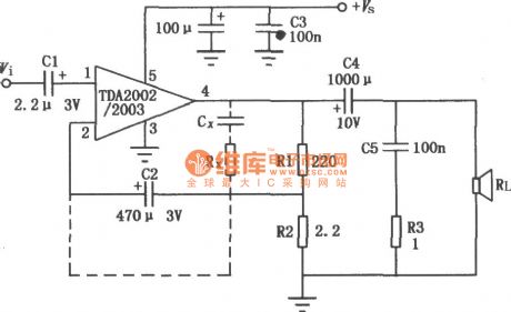
8 Watts Audio Amplifier (TDA2003)
Published:2012/9/10 21:14:00 Author:Ecco | Keyword: 8 Watts, Audio Amplifier
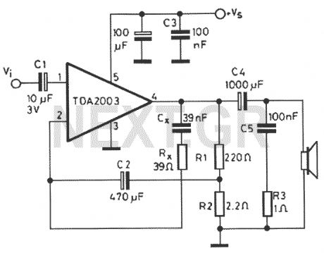
Nice small audio amplifier which use only few parts to give good quality sound. This amp can be used as a simple booster, the heart of a more complicated amplifier or used as a guitar amp. Although not perfect, this amplifier does have a wide frequency response, low harmonic distortion about 1.5%, and is capable of driving an 8 ohm speaker to output levels of around 8 watts with slightly higher distortion.
Source: discovercircuits (View)
View full Circuit Diagram | Comments | Reading(1939)
Offset controlled stereo amplifier circuit
Published:2012/9/10 21:02:00 Author:Ecco | Keyword: Offset controlled, stereo amplifier
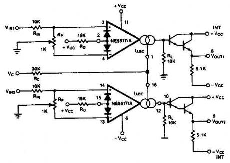
This stereo amplifier use the NE5517/A and has an excellent tracking of 0.3 dB typical easy. With the potentiometer, Rp, the offset can be adjusted. For AC-coupled amplifiers, the knob can be replaced by two resistors 5.1 k ohm.
Source: discovercircuits (View)
View full Circuit Diagram | Comments | Reading(2)
2 Watt stereo amplifier with LM1877N-9
Published:2012/9/10 20:59:00 Author:Ecco | Keyword: 2 Watt , stereo amplifier
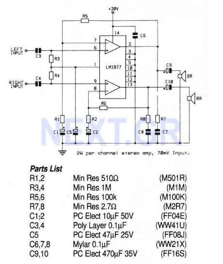
This circuit uses a stereo amplifier IC in a 14-pin DIL package that requires very few external components to make a complete 2 Watt per channel power amplifier.
Source: discovercircuits (View)
View full Circuit Diagram | Comments | Reading(1)
Stereo Preamplifier with balance and loudness
Published:2012/9/10 20:58:00 Author:Ecco | Keyword: Stereo Preamplifier , balance , loudness
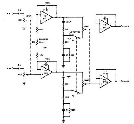
The circuit of preamplifier use the 5533 chip and features a combination of controls balance and volume. Due to the nonlinearity of the human auditory system, low frequencies must be boosted at low listening levels. Level pay, and LOUDNESS controls provide all the plays to produce the desired response from the music.
Source: discovercircuits (View)
View full Circuit Diagram | Comments | Reading(5090)
Voltage-controlled 4W audio amplifier circuit diagram
Published:2012/7/11 2:14:00 Author:Ecco | Keyword: Voltage-controlled , 4W , audio amplifier
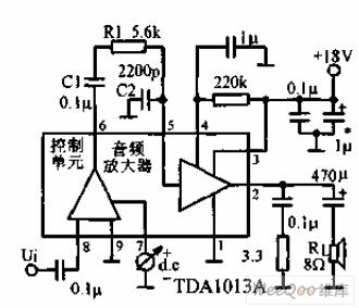
Voltage-controlled 4W audio amplifier uses audio amplification IC TDA103Ato provide4W of output power. The control voltage is3.5 ~ 8V, and controlcharacteristic is logarithmic with controlling rangein 80dB.
(View)
View full Circuit Diagram | Comments | Reading(1596)
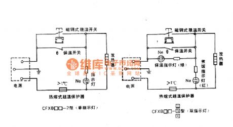
Rongsheng heat insulation automatic electric cooker principle diagram
Published:2011/8/30 1:40:00 Author:Jessie | Keyword: Rongsheng , heat insulation, automatic electric cooker
View full Circuit Diagram | Comments | Reading(839)
YS-608 Learning headset principle and maintenance circuit
Published:2011/8/24 2:30:00 Author:Jessie | Keyword: Learning headset, principle, maintenance
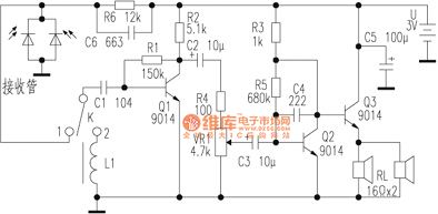
The headset circuit entirely composedof division components. When single pole double throw switch K is dialled to 1 position, the headset is at the state ofreceiving infrared, thereceiver tube will receive infrared speech signal from 100 parallel infrared emitting tubes which are in the back of the classroom. This signal is coupledfrom the capacitor C1 to Q1 to amplify, then the voice signal issent to the two level percentile amplifier circuit which is composedof Q2, Q3, and promote left/right two parallel headsets togive off sound. (View)
View full Circuit Diagram | Comments | Reading(853)
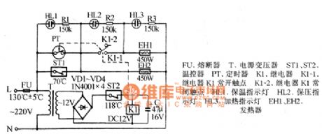
Banqiu HE-2700E1, HE-2700E2 temperature-regulating electric furnace circuit diagram
Published:2011/8/29 22:37:00 Author:Jessie | Keyword: Banqiu, temperature-regulating , electric furnace
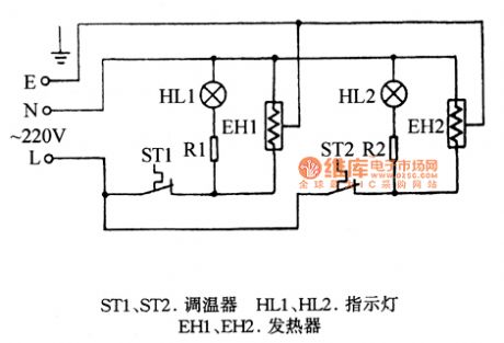
ST1, ST2-thermostat, HL1.HL2-light, EH1, EH2 heater
(View)
View full Circuit Diagram | Comments | Reading(793)
Meifeng DYB40-80A insulation automatic electric pressure cooker circuit
Published:2011/8/24 2:37:00 Author:Jessie | Keyword: insulation, electric pressure cooker
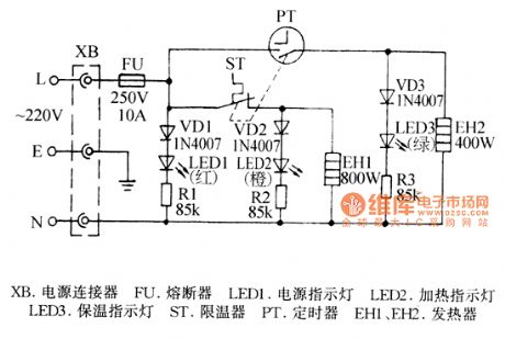
XB-power connector, FU-fuse, PT-timer,EH1,EH2-heater,led1-power indicator, LED2-heater indicator, LED3-heater lamp (View)
View full Circuit Diagram | Comments | Reading(781)
Jiabao YWB-55 automatic electric pressure cooker circuit
Published:2011/8/24 2:33:00 Author:Jessie | Keyword: electric pressure cooker
FU-Fuse, T-power transformer, ST1, ST2-thermostats, PT-timer, K1-relay, K1-1 normally open contact of relay K1, K1-2-relay normally closed contact of K1, HL1-heat indicator, EH1, EH2-heaters (View)
View full Circuit Diagram | Comments | Reading(1207)
Integrated audio power amplifier circuit LM380
Published:2011/12/1 1:57:00 Author:Ecco | Keyword: Integrated, audio power amplifier
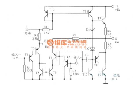
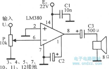
LM380 internal equivalent circuit :
LM380 application circuit:
(View)
View full Circuit Diagram | Comments | Reading(3623)
TDA2009 mono and stereo audio power amplifier circuit diagram
Published:2011/10/20 21:12:00 Author:Rebekka | Keyword: mono , stereo audio , power amplifier

Pin 1: 1.2V-- left channel input Pin 2: 0.8V-- left channel feedback Pin 3: 12V - Squelch Pin 4: 0.8V--right channel feedback Pin 5: 1.2V--right channel input
Pin 6: 0V - groundPin 7: 0V - empty Pin 8: 12.4V-- right channel outputPin 9: 24V - Power Pin 10: 12.4V-- left channel output (View)
View full Circuit Diagram | Comments | Reading(5059)
Hi fi audio power amplifier circuit
Published:2011/8/24 2:26:00 Author:Jessie | Keyword: Hi fi audio power amplifier
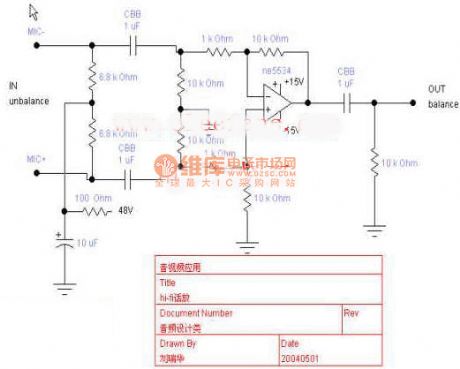
Hi fi audio power amplifier circuit: if you want to get high quality recording, you should have a good phone,but you must use high quality amplifier. This amplifier uses the tiny distortion ne5534, and itis listening to be soft and delicate. (View)
View full Circuit Diagram | Comments | Reading(1098)
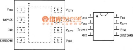
LM4910 stereo headphone amplifier circuit diagram
Published:2011/8/31 2:32:00 Author:Rebekka | Keyword: stereo headphone amplifier
LM4910 is an audio power amplifier. It is primarily designed for portable devices, and it uses 3.3V power supply. It can output 35mW continuous average power todriver 32Ω load. LM4910 uses new topology circuit to cancle headphone amplifier output coupling capacitor and half-supply bypass capacitor, and it includes an advanced click - flutter noise elimination circuit. This noise generates instantly when you switch it off. LM4910 pinout is shown as the chart.
(View)
View full Circuit Diagram | Comments | Reading(990)
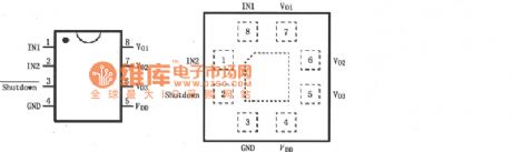
LM4809, LM4810 typical circuit diagram for two-channel headphone amplifier
Published:2011/8/31 2:34:00 Author:Rebekka | Keyword: two-channel headphone amplifier, typical circuit
Left and right channel audio signals are input M4809/4810(SOP/MSOP packaging) 2, 6 feet respectively. They are output by 1, 7 feet after being amplified by the internal amplifier. They will be added to the respective channel speaker through coupling capacitor. Amplifier gain Av = Rf / Ri. LM4809's pin 5 is connected externalshutdown control. when pin 5 is connected to VDD(high level), it is allowed to work; when pin 5 is grounded(low level), it can not work.
(View)
View full Circuit Diagram | Comments | Reading(1933)
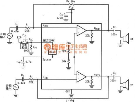
LM4809, LM4810 Dual-channel headphone amplifier circuit diagram
Published:2011/8/31 2:35:00 Author:Rebekka | Keyword: Dual-channel , headphone amplifier
LM4809/4810 is dual channel headphone amplifier with 5V power supply. Each channel can output 105mW continuous average power to drive 16Ω load. Total harmonic distortion plus noise (THD + N) is only 0.1%. LM4809/4810 isthe minimum number of external components, which canprovide high-quality output power. LM4809/4810 does not require bootstrap capacitor and buffer. It is qualified to low-power portable systems. LM4809/4810 has an external control terminal to produce effectivelow level shutdown mode to work in the micro-power. There is an internal thermal shutdown protection agency. The pinout is shown as the chart.
(View)
View full Circuit Diagram | Comments | Reading(1232)
TDA2002, TDA2003 8W Audio power amplifier circuit diagram
Published:2011/8/31 2:35:00 Author:Rebekka | Keyword: 8W , Audio power amplifier
View full Circuit Diagram | Comments | Reading(3858)
| Pages:4/13 12345678910111213 |
Circuit Categories
power supply circuit
Amplifier Circuit
Basic Circuit
LED and Light Circuit
Sensor Circuit
Signal Processing
Electrical Equipment Circuit
Control Circuit
Remote Control Circuit
A/D-D/A Converter Circuit
Audio Circuit
Measuring and Test Circuit
Communication Circuit
Computer-Related Circuit
555 Circuit
Automotive Circuit
Repairing Circuit