
Amplifier Circuits-Audio
Index 2
Simple LM386 Audio Amplifier
Published:2013/3/25 3:21:00 Author:Ecco | Keyword: Audio Amplifier
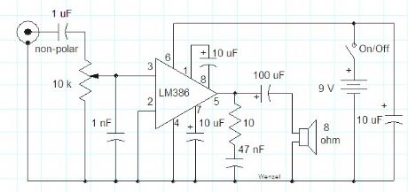
This simple amplifier shows the LM386 in a high-gain configuration (A = 200). For a maximum gain of only 20, leave out the 10 uF connected from pin 1 to pin 8. Maximum gains between 20 and 200 may be realized by adding a selected resistor in series with the same 10 uF capacitor. The 10k potentiometer will give the amplifier a variable gain from zero up to the maximum.
(View)
View full Circuit Diagram | Comments | Reading(2266)
1W Audio Amplifier Circuit based TDA7052
Published:2013/3/18 2:03:00 Author:Ecco | Keyword: 1W , Audio Amplifier
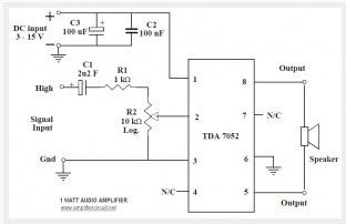
This is the 1 Watt power audio amplifier based Phillip IC TDA7052. The circuit can be used for small audio amplification. The circuit is very simple and easy to build. It only required 5 external components to support the main power IC. Ideal supply voltage is 6V to 12 VDC. R2 is a linear potensiometer to adjust the volume.
(View)
View full Circuit Diagram | Comments | Reading(2217)
Single Chip Audio Preamplifier LM358
Published:2013/3/18 1:10:00 Author:Ecco | Keyword: Single Chip, Audio Preamplifier
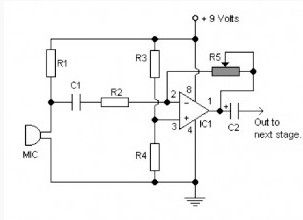
The circuit is based on low power ic LM358 dual op amp with a single 9 volt power supply. This pre amp has a gain which can be set via the variable resistor R5.
(View)
View full Circuit Diagram | Comments | Reading(4695)
Simple Audio Booster
Published:2013/3/18 1:09:00 Author:Ecco | Keyword: Audio Booster
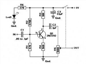
This Audio booster circuit is very simple and can be applied to fm tuner or audio pre amplifier. The 2N3392 is a low-noise type transistor in TO-92 case. The transistor can can be replaced by a NTE199 or ECG199. If you wish to use a TUN, cross reference the parameters with one of the units from this list : TUP-TUN
Potentiometer R5 of 100K is a linear type with an on/off switch attached. The value of C1 may need to be between 0.05µF and 0.1µF (47nF/100nF). Experiment with the value for best performance.
(View)
View full Circuit Diagram | Comments | Reading(1437)
2x22W Car Audio Amplifier Circuit
Published:2013/3/18 1:08:00 Author:Ecco | Keyword: 2x22W, Car, Audio Amplifier
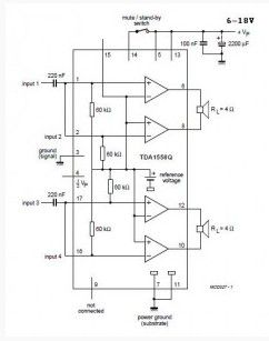
Above is a schematic diagram of an amplifier which is used in car audio. This circuit uses IC TDA 1558 from Philips. TDA1558 is a monolithic integrated class-B Output power amplifier in 17-lead single-in-line (SIL) plastic package. The device contains 4 x 11 W single-ended or 2 x 22 W BTL amplifiers.
(View)
View full Circuit Diagram | Comments | Reading(1903)
High Quality Audio Amplifier for Computer
Published:2013/3/18 1:00:00 Author:Ecco | Keyword: High Quality, Audio Amplifier, Computer
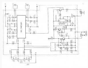
Using a modern element base import, is not difficult to self-assemble high-quality audio amplifier. It will take only one chip firms TOSHIBA. You do not need adjustment, which implies the presence of costly instrumentation.
The electrical circuit of the amplifier is shown in Fig. 1. For its production is chosen in a typical IC TA8205AN inclusion. Usually it is applied to a Hi-Fi class due to low harmonic distortion. Suitable as a similar but more powerful: TA8210AN TA8215AN and (wiring diagram in this case does not change).
Unlike many other types, except for low harmonic distortion in the chip provides for work in standby mode, ie with low power consumption from the power supply in case the input DA1 / 4 zero. In addition, the amplifier provides a soft inclusion, eliminating the clicks in the speakers when power is applied.
(View)
View full Circuit Diagram | Comments | Reading(1405)
High Precision Audio Frequency Amplifier based LM4702
Published:2013/3/15 4:15:00 Author:Ecco | Keyword: High Precision, Audio Frequency Amplifier
New chip LM4702 from National Semiconductor allows you to create audio-frequency amplifiers (AF) with a nominal output power of 300 W and low noise. A characteristic feature of this chip is a high level voltage, which allows high power output when using external transistors.Practice shows that the use of power amplifier circuits AF (audio frequency) performed on a single chip, the main factor in choosing components for reproducing parts of the developed device are easy to set up and a small number of elements binding. However, in most cases the quality of the sound signal does not fall under the class HI-FI in connection with a high percentage of non-linear distortion.
This fact is associated not only with engineering solutions such chips, but the fact that the temperature of the elements of input and output stages are directly dependent on each other.
(View)
View full Circuit Diagram | Comments | Reading(2201)
Headphone Audio Amplifier based Two Transistors
Published:2013/3/14 3:23:00 Author:Ecco | Keyword: Headphone Audio Amplifier, Two Transistors
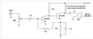
TheHeadphone audio amplifier based two Transistors circuit is very simple and easy to construct, the main component is built with only two transistors 2N3565 and 2N3706.Headphone Audio Amplifier Power supply can use a 9V battery. Output Headphone Amplifier can be connected with a 32 or 64 ohm headphones.
(View)
View full Circuit Diagram | Comments | Reading(1613)
General Purpose 10 Watt Audio Amplifier Circuit
Published:2013/3/14 3:21:00 Author:Ecco | Keyword: General Purpose , 10 Watt, Audio Amplifier
This circuit is a general purpose 10-W power audio amplifier for medium power amplifier or use a modulation in the AM transmitter. For higher power up to 30 W can be obtained by increasing the voltage and change the bias resistor value.
(View)
View full Circuit Diagram | Comments | Reading(1643)
10 Watt Transistor audio amplifier
Published:2013/3/14 2:48:00 Author:Ecco | Keyword: 10 Watt Transistor , audio amplifier
This circuit can have a power output of 10 Watt. It simply uses ordinary transistors. The 10 w amplifier circuit is unstable if the input is not connected. When performing the test, connect a resistor (about 3k3).
(View)
View full Circuit Diagram | Comments | Reading(1638)
5.8 W Audio Power Amplifier
Published:2013/3/14 2:42:00 Author:Ecco | Keyword: 5.8 W, Audio Power Amplifier
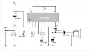
This TA7222AP scheme used for audio signal amplifiers. The circuit delivers 5.8 W with power off Control. 8-12V power supply can be used for this circuit ant it is a good idea to use for car audio amplifier, coin-op gaming machines, security systems, etc.
(View)
View full Circuit Diagram | Comments | Reading(1606)
Low Voltage Bridge Audio Amplifier
Published:2013/3/13 2:05:00 Author:Ecco | Keyword: Low Voltage, Bridge Audio Amplifier
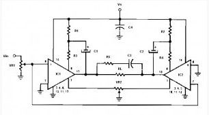
Low voltage bridge audio amplifier based on op amp IC LM386 (Low Voltage Audio Power Amplifier). Application of this circuit include AM-FM radio amplifiers, Portable tape player amplifiers, intercoms, TV sound systems, Line drivers Ultrasonic drivers, Small servo drivers Power converters. This circuit can be operated by battery power.
This Low voltage bridge audio amplifier circuit is for low voltage applications requiring high power outputs. Output power levels of 1.0 W into 4 ohm from 6 V-and 3.5 W into 8 ohm from 12 V are typical. Coupling capacitors are not necessary since the output dc levels will-be within a few tenths of a volt of each other. Where critical matching is required the 500 K potentiometer is added and adjusted for zero dc current flow through the load.
(View)
View full Circuit Diagram | Comments | Reading(2055)
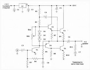
35W Audio Amplifier based LM391
Published:2013/3/13 1:20:00 Author:Ecco | Keyword: 35W , Audio Amplifier
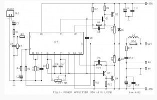
This is the circuit diagram of a 35W audio amplifier based on LM391. The LM391 is a comprehensive driver to the power transistors. It needs only few external components to work. With the TR1 we can adjust the bias current to 45mA. Inductor L1 consists of 20 turns of wire thickness of 0.9mm, around the resistor R16. The transistors Q3-4 must be placed onto a heatsinks. If you use the Q3-4 with type of TIPxxxx, you can be placed directly onto the board. But if you use packaged transistors TO-3, then it should be connected with short cables to the respective positions of the board.
(View)
View full Circuit Diagram | Comments | Reading(1654)
5 Watt Audio Amplifier based LA4460
Published:2013/3/13 1:02:00 Author:Ecco | Keyword: 5 Watt, Audio Amplifier
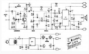
This 5 W audio power amplifier is built for general purpose and can drive speakers approximately 8 to 12 inches. This 5W power amplifier circuit is based on the Sanyo LA4460 IC which used as an audio output.
This Low-power amplifier circuit have built in loudness control, driver amplifier Q1, and the bass/treble controls of around ± 10 dB boost / cut. It would be useful in a wide variety of situations. Either displayed ac supply can be used, or 12 VDC supply can be connected to points A & B (positive) and C (negative).
For stereo circuit can be used two of this circuit by using ganged potentiometer at R2, R7 and R11. T1 is 12V at 1 ampere plug-in transformer.
(View)
View full Circuit Diagram | Comments | Reading(1621)
General Purpose 5 Watt Audio Amplifier based LA4460
Published:2013/3/12 1:42:00 Author:Ecco | Keyword: General Purpose , 5 Watt, Audio Amplifier
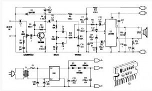
The 5 Watt audio amplifier shown here are suitable for driving the speaker size 8 to 12 inch. Here used an audio output from Sanyo LA4460 IC. The IC is actually used for car radio or car audio power amplifier and may deliver output power up to 12 W. But in this circuit is only used 5W.
The 5 W audio amplifier circuit consists of loudness control, driver amplifier Q1, and the bass and treble controls of approximately ± 10 dB boost / cut. Either the ac supply shown in here can be used, or a 12 Vdc supply can be connected to points A&B (positive) and C (negative). Two of these circuits, using ganged potentiometers at R2, R7, and R11 can be used for stereo applications. T1 is a 12Volt 1 ampere plug-in transformer. Notice that IC1 must be heatsinked. Power output is about 5 W. A 4″ x 2″ x 0.050″ aluminum heatsink should be adequate.
(View)
View full Circuit Diagram | Comments | Reading(1285)
30 watt audio amplifier based TDA2040
Published:2013/3/12 1:37:00 Author:Ecco | Keyword: 30 watt , audio amplifier
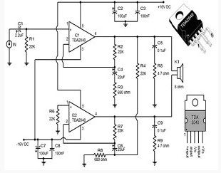
A 30 watt audio amplifier circuit using TDA2040 are shown here. TDA2040 is class AB monolithic integrated audio amplifier available in the package Pentawatt. The IC has a low harmonic distortion and has a built in circuit protection for short circuit.
In the circuit, two TDA2040 ICs are wired in BTL (bridge-tied load) configuration to provide 30W of output into 8 ohm speakers at + /-16V DC. The capacitor C1 is the decoupling capacitor DC input. Network with components R2, C4, R3 provides feedback for IC1 while R7, C6, R8 network provides information for IC2. Network C5, R5 and C9, R9 provides stability at high frequency. Capacitors C2, C3 filters the positive supply rail while the capacitors C7, C8 filters the negative supply rail.
(View)
View full Circuit Diagram | Comments | Reading(3877)
6 Watt HI FI audio amplifier based TDA2613
Published:2013/3/12 1:36:00 Author:Ecco | Keyword: 6 Watt , HI FI , audio amplifier
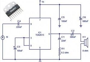
The 6 watt audio amplifier circuit using TDA2613 are shown here. TDA2613 is a Hi-Fi integrated audio amplifier IC from Philips Semiconductors. The IC is ON / OFF button click proof, short circuit, thermal protection and are available only in the 9-pin plastic package inline.
In the above circuit, TDA2613 is wired to operate from a single supply. The capacitor C4 is a DC input coupler while the capacitors C5, C6 are power supply filters. Audio input is fed to the noninverting input through capacitor C4. Inverting input and Vp / 2 pins of the IC are tied together and grounded by the capacitor C3. Capacitor C2 couples the speaker to the output IC and network comprising capacitors C1 and resistor R1 increases stability at high frequency.
(View)
View full Circuit Diagram | Comments | Reading(1451)
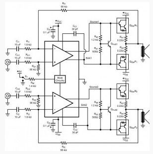
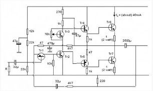
36 Watt Audio Power Amplifier based on TDA1562Q
Published:2013/3/12 1:31:00 Author:Ecco | Keyword: 36 Watt, Audio Power Amplifier
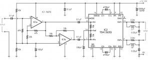
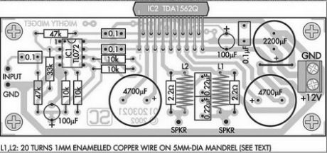

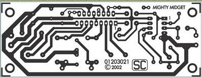
The amplifierbased on theclassHfromPhilipsaudioamplifierIC,itcandeliver36WRMS and 70Wpower music,allfromthe supplyvoltage of13.8V. Thisamplifiercanprovide36WRMScontinuousinto4ohmloadwhen using a13.8Vsupply.
However,itisable todeliver70Woutputpowersignal(music)inthe dynamiccondition. As we cansee fromthe drawingsand schematic diagrams,thispowerfulamplifieruses onlyfewpart.
As we cansee fromthe schematicdrawingsanddiagrams,thispowerfulamplifieruses onlyfewpart. It is builton aPCBsize104mmx39mm,buteven thoughits sizemay be simple,butnot withhis ability.Thisamplifieralsohas excellentnoise anddistortion. An importantcomponentsof the circuit isan integratedcircuitTDA1562Q”monolithic integratedBridgeTiedLoad (BTL)classHpower amplifierwithhighefficiency.”Formin17-pinpackage “DIL-bent-SIL”plasticandnotonlydesignedfor use incaraudio amplifier and portablePAbut it worksfor network applications,for example,mini/midiaudio componentsandforTV sound.
PCB :
Technicalfeature:Output power36WRMS:———————-4R70Wmusic power:—————————– 4RFrequency response:28Hztolow———–1dBand 55kHz130mVinput sensitivity:——————— RMS(36Wfor4-ohm)Harmonic distortion:————————– typically0.2% (see charts)SNR95dBunweighted:————————(22Hz to22kHz)
(View)
View full Circuit Diagram | Comments | Reading(4079)
10W MOSFET audio amplifier circuit
Published:2013/3/12 1:28:00 Author:Ecco | Keyword: 10W, MOSFET, audio amplifier
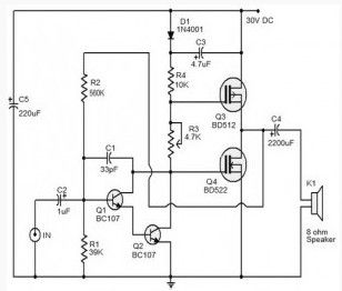
The schemepresented hereis aMOSFET10Waudioamplifier circuitwhichrequires only single power supply. Singlerailsupply is rarely used inClass-Bpower amplifiers. Anyway, it’sgoodenough forlowpower applications. In fact,this circuit is takenfromoldcassette playerthat still works.
PowerMOSFETBD522andBD512is nowobsolete, so you canuseother powerMOSFETaccording toitscharacteristics. Q1andQ2arewiredas apairDarlingtontransistorthat serves as apreamplifier. R3Presetcontrols thequiescent currentwhileR2providing feedback.The outputcoupled to the speakerthroughcapacitorC4.capacitorC5Is apowerfilterandC2isdecouplingcapacitorforDCinput.
(View)
View full Circuit Diagram | Comments | Reading(3274)
Two way 20 watts audio amplifier
Published:2013/3/12 1:27:00 Author:Ecco | Keyword: Two way , 20 watts, audio amplifier
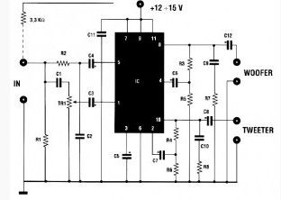
This is a20 watts audio amplifieris suppliedwith a voltage14.4volts,givinga total power of20wattsinto twodifferent channels, each of whichis connectedto thetweeteranda woofer. This amplifier isthereforeequipped with an active CROSSOVERfilterwithacrossoverfrequencyof 2KHz. Eachloudspeakermust supporta power of 10wattsandhaveanimpedanceof 4 ohms.
The supply voltagecan bebetween12and up to 15volts. This two way amplifiercan also bebeneficially usedas aBOOSTERfor2 wayradio.In this case, it is necessaryto place a3.3Kohmresistorbetween theoutputof theradioandthe amplifierinput(seediagram). Toavoid unpleasantdistortion,we mustavoidto applyinputsignalsgreater than 50 mV.
(View)
View full Circuit Diagram | Comments | Reading(1348)
| Pages:2/13 12345678910111213 |
Circuit Categories
power supply circuit
Amplifier Circuit
Basic Circuit
LED and Light Circuit
Sensor Circuit
Signal Processing
Electrical Equipment Circuit
Control Circuit
Remote Control Circuit
A/D-D/A Converter Circuit
Audio Circuit
Measuring and Test Circuit
Communication Circuit
Computer-Related Circuit
555 Circuit
Automotive Circuit
Repairing Circuit