
Amplifier Circuits-Audio
Index 6
50_mW_FLAT_TO_30_kHz
Published:2009/6/29 22:09:00 Author:May
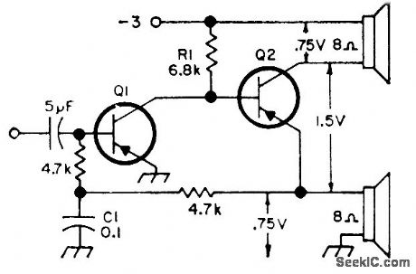
Power amplifier achieves push-pull output with single transistor. Both transistors should be germanium such as 2N404 SK3004 or HEP-253.-Circuits, 73 Magazine, Feb. 1974, p 100. (View)
View full Circuit Diagram | Comments | Reading(2134)
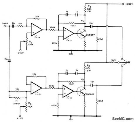
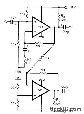
ERROR_ADD_ON_REDUCES_DISTORTION
Published:2009/6/29 2:54:00 Author:May
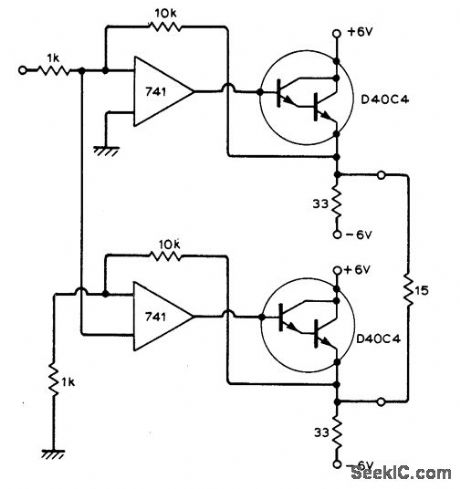
Based on fact that error at output of upper opamp also appears at input of this opamp, Error signal is taken from this input for lower opamp, where it is amplified by opamp and Darlington for addition to output of upper Darlington. Article gives design equations and intimates that open-loop gain improves at 12 dB per octave as compared to conventional 6 dB, Applications include reduction of loudspeaker distortion which cannot be handled by negative feedback.-A.Sandman, Reducing Distortion by 'ErrorAdd-On.' Wireless World, Jan. 1973, p 32. (View)
View full Circuit Diagram | Comments | Reading(785)
75_W_WITH_CURRENT_LIMITING
Published:2009/6/29 2:27:00 Author:May
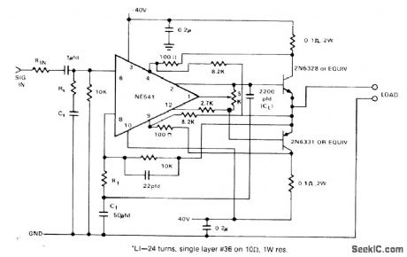

Signetics NE541 high-voltage power amplifier provides current gain of 90 dB from 20 Hz to 20 kHz andoutput levels up to 20 VRMS from 300-mVRMS input.IC includes built-in short-circuit protection,with additional protection provided by external current limiting,Transistors in output stage boost power to 75 W for driving loud-speaker load.- Signetics Analog Data Manual, Signetics, Sunnyvale, CA, 1977, p 765 (View)
View full Circuit Diagram | Comments | Reading(1342)
60_W
Published:2009/6/29 2:05:00 Author:May
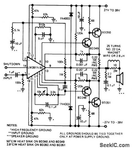
Combination of National LM391 audio driver 10 and discrete power transistors provides 60-W output for loudspeaker at very low distortion. IC output can swing ±40V.Totalharmonic distortion of circuit is under 0.05%.-P.Franson, Consumer-Product IC's-New Offerings Trtgger an Explosion in Markets Old and New,EDN Magazine, Nov.5,1977,p 54-65. (View)
View full Circuit Diagram | Comments | Reading(2708)
1_W_NONINVERTING_WITH_SPLIT_SUPPLY
Published:2009/6/29 2:00:00 Author:May
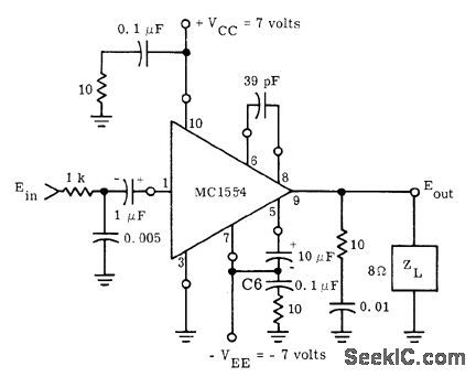
Motorola MC1554 IC is connected for operation from ±7 V to provide voltage gain of 9 overfre。quency range(-3 dB)of 40 to 22,000 Hz,Inputimpedanceis 10K,and total harmonic distortionis is less than 0.75%, Use external heatsink,-″The MC1554 One-Watt Monolithic Integrated Circtiit Power AmpIifier, Motorola、 Phoenix,AZ,1972、AN-401、p 2 (View)
View full Circuit Diagram | Comments | Reading(796)
1_W_NONINVERTlNG
Published:2009/6/29 2:00:00 Author:May
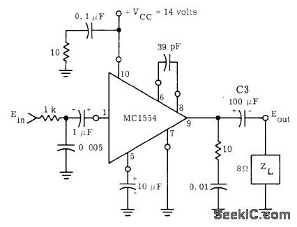
Motorola MC1554 IC operates from single supply and uses capacitive coupling to both source and load, for voltage gain of 9 with frequency response (-3 dB) from 200 to 22,000 Hz. Input impedance is 10K, and total harmonic distortion is Iess than 0.75%.Use external heatsink.- The MC1554 One-Watt Monolithic Integrated Circuit Power Am-plifier, Motorola, Phoenix, AZ, 1972, AN-401, p 2. (View)
View full Circuit Diagram | Comments | Reading(766)
5_W_CLASS_A
Published:2009/6/29 2:00:00 Author:May
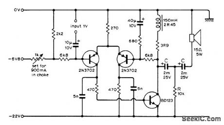
Three-transistor feedback loop gives excellent DC stability, while arrangement of two capacitors and resistor feeding loudspeaker keeps these capachors properly polarized as AF output voltage swings above and below zero Ievel.-R. H. Pearson, Novel 5-Watt Class A Amplifier Uses Three-Transistor Feed-back Circuit, Wl'reless World, March 1974, p 18. (View)
View full Circuit Diagram | Comments | Reading(929)
ELECTROSTATIC_HEADPHONES
Published:2009/6/29 1:54:00 Author:May
Uses LM3900N four-opamp IC and two transistors to step up headphone output signal of AF power amplifier sufficiently to drive pair of electrostatic headphones without introducing excessive distortion. Total harmonic distortion at 1 kHz is 1% at 300-V peak-to-peak output, and dropsto 0.1% at 50-V output.-N. Pollock, Elec-trostatic Headphone Amplifier, Wireless World, July 1976, p 35. (View)
View full Circuit Diagram | Comments | Reading(2905)
BALANCED_OUTPUT_WITH_OPAMPS
Published:2009/6/29 1:53:00 Author:May
Low-cost amplifier provides lowimpedance balanced output from unbalanced signal output of preamp. Response is flat from 10 to 20,000 Hz, and distortion less than 0.1% at 800 Hz into 600-ohm load. Gain is 20 dB. Other opamps, such as LM307 or 747 (dual 741) can also be used.K. D. James, Balanced Output Amplifier, Wireless World, Doc. 1975, p 576. (View)
View full Circuit Diagram | Comments | Reading(3232)
15W audio power amplifier circuit diagram composed of OPA604
Published:2011/8/1 3:03:00 Author:Ecco | Keyword: 15W , audio power amplifier
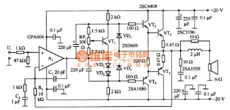
Figure 1 is l5W audio power amplifier circuit constituted by the OPA604. OPA604 has FET-input with the working voltage in ± 25V, and the conversion rate in 25V/μs, and GB is the 2OMHz excellent high-frequency op amp, which is used as the pre-amplifier to get low-level distortion. RP1 is used to adjust the load current of power transistor in 35mA; VD3 and VD4 are used to limit output current in short circuit, and when the circuit works normally, they are in the cut-off state.
(View)
View full Circuit Diagram | Comments | Reading(4641)
HIGH_OUTPUT_CUfIRENT
Published:2009/6/29 1:49:00 Author:May
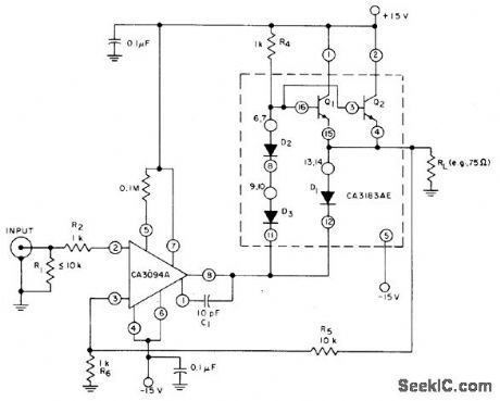
Uses CA3094A programmable opamp as driver stage for two parallel-connected transistors of CA3183AE arrayto develop 100-mA average AF current(peaks up to 300mA)through 75-ohm load,Diode-connected transistors D1-D3 in array provide temperature compensation for output tranperature- Circuit ldeas for RCA Linear ICs、″RCA solid State Division Somerville,NJ,1977、p11 (View)
View full Circuit Diagram | Comments | Reading(801)
60_W_WITH_AC_COUPLED_OUTPUT
Published:2009/6/29 1:48:00 Author:May
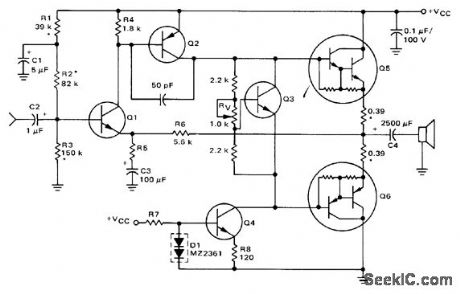
Uses Motorola complementary Darlington output transistors, with MJE6044 for Q5 and MJE6041 for Q6. For 8-ohm loudspeaker, Q1 is MPS-A06 Q2 is MPS-A56, Q3 is MPS-A13 and Q4 is MPS-A06 Supply is 72 V. R5 is Z20 ohms, and R7 is 68K Same circuit is used wjth different components for other output powers down to 15 W and for 4-ohm loudspeaker. Frequency response is 20 Hz to 50 kHz for -1 dB points.-R. G. Ruehs, 15 to 60 Watt Audio Amplifiers Using Comple mentary Darlington Output Transistors, Mo-torola, Phoenix, AZ, 1974, AN-4B3B, p 3. (View)
View full Circuit Diagram | Comments | Reading(5948)
The duty cycle adjustable square wave generator circuit composed of 555
Published:2011/7/24 1:51:00 Author:Seven | Keyword: duty cycle, square wave generator
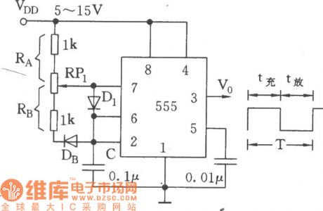
Once the circuit was added with a voltage VDD, the oscillator would start the oscillate. When the circuit is connected, as the voltage on C can't mutate, i.e the 2-pin LEV is the earth LEV firstly, which makes 555 offset, 3-pin is in a high LEV. C charges the generator through RA and D1, the charge time is tc=0.693RAC, when the voltage on C rises to 2/3VDD, 555 is reset, 3-pin is in a low LEV, at this moment, C discharge with the help of D1, R8 and the discharge tube in 555, the discharge time is td=0.693RbC. (View)
View full Circuit Diagram | Comments | Reading(2647)
High-precision pressure amplifier circuit composed of the AD624
Published:2011/6/27 0:12:00 Author:Rebekka | Keyword: High-precision pressure amplifier
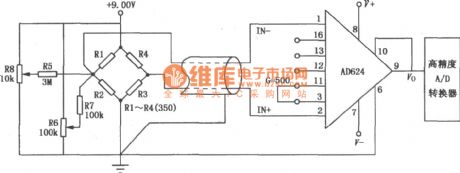
High-precision pressure amplifier circuit is mainly used in small amplification system. The AD624 is a precision low-noise instrumentation amplifier which can be used in a small sensor output signal amplification system. The figure shows the high-precision pressure amplifier circuit composed of the AD624. The sensor is a standard strain gauge bridge sensors. The bridge voltage uses+ 9.00V, potentiometers R8 and R6 to zero, in which R6 is coarse, R8 is fine. The amplifier output can be directly related to high-precision A / D converter connected. (View)
View full Circuit Diagram | Comments | Reading(1822)
SIMPLE_TEST_AUDIO_AMPLIFIER
Published:2009/6/19 2:53:00 Author:May
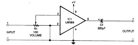
This circuit has a gain of about 20. A suitable power supply voltage is 5 to 12 V, depending on the desired audio output power level. (View)
View full Circuit Diagram | Comments | Reading(765)
HIGH_POWER_12_V_IC_AUTO_AMPLIFIER
Published:2009/6/19 2:29:00 Author:May
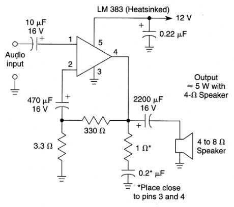
View full Circuit Diagram | Comments | Reading(821)
HIGH_POWER_AUDIO_AMP_FOR_AUTOMOTIVE_INSTALLATION
Published:2009/6/19 2:29:00 Author:May
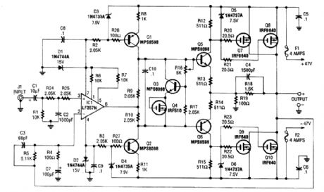
Two of these audio amplifiers can be used to make a stereo amplifier 200W per channel. IRF640 and IRF9640 power MOSFETs are used to drive the output load, which might be 4 or 8Ω. Response is 12 Hz to 45 kHz (-3 dB), THD <0.1%. Power is supplied by a switching-type power supply, which is external to the amplifier (±47V). About 600 W total power (peak) is needed. (View)
View full Circuit Diagram | Comments | Reading(8630)
80_WATT_IC_AUDIO_AMPLIFIER
Published:2009/6/19 1:54:00 Author:May
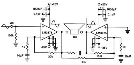
This audio power amp will deliver 80W of audio into an 8-Ω load The LM3875 IC devices shouldbe suitably heatsinked。Note that the amplifier IS a bridged circuit,with both speaker leads“hot.” (View)
View full Circuit Diagram | Comments | Reading(2044)
LINE_OPERATED_AUDIO_AMPLIFIER
Published:2009/6/19 1:41:00 Author:May
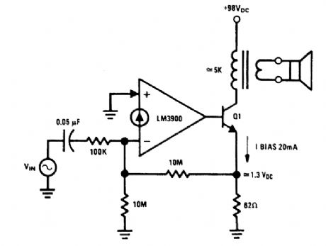
An audio amplifier which operates off a +98-Vdc power supply (the rectified line voltage) is of-ten used in consumer products. The external high-voltage transistor, Q1, is biased and controlled by the LM3900. The magnitude of the dc biasing voltage, which appears across the emitter resistor of Q1 is controlled by the resistor. The resistor is placed from the (-) input to ground. (View)
View full Circuit Diagram | Comments | Reading(816)
10_WATT_AUDIO_AMPLIFIER
Published:2009/6/19 1:39:00 Author:May

This circuit is a general-purpose 10-W audio amplifier for moderate-power PA or modulator use in an AM transmitter. With higher voltages and a change in bias resistors, up to 30 W can be obtained. (View)
View full Circuit Diagram | Comments | Reading(1249)
| Pages:6/13 12345678910111213 |
Circuit Categories
power supply circuit
Amplifier Circuit
Basic Circuit
LED and Light Circuit
Sensor Circuit
Signal Processing
Electrical Equipment Circuit
Control Circuit
Remote Control Circuit
A/D-D/A Converter Circuit
Audio Circuit
Measuring and Test Circuit
Communication Circuit
Computer-Related Circuit
555 Circuit
Automotive Circuit
Repairing Circuit